Page 675 of 1456

4) Remove rear cover by loosening retaining
bolts.
G3M1032
5) Make right and left side bearing retainers in
order to identify them at reassembly. Remove side
bearing retainer attaching bolts, set ST to differen-
tial carrier, and extract right and left side bearing
retainers with a puller.
CAUTION:
Each shim, which is installed to adjust the side
bearing preload, should be kept together with
its mating retainer.
ST 398457700 ATTACHMENT
G3M1034
6) Pull out differential assembly from differential
carrier.
CAUTION:
Be careful not to hit the teeth against the case.
G3M1035
7) When replacing side bearing, pull bearing race
from side bearing retainer using ST.
ST 398527700 PULLER ASSY
B3M0871A
8) Extract bearing cone with ST.
CAUTION:
Do not attempt to disassemble the parts unless
necessary.
NOTE:
ISet puller so that its claw catch the edge of the
bearing cone.
INever mix up the right and left hand bearing
races and cones.
ST 399527700 PULLER SET
G3M0068
9) Remove crown gear by loosening crown gear
bolts.
CAUTION:
Further disassembling is not allowed.
G3M0069
25
[W2C1]3-4SERVICE PROCEDURE
2. Rear Differential
Page 676 of 1456

10) Drive out pinion shaft lock pin from crown gear
side.
NOTE:
The lock pin is staked at the pin hole end on the
differential case; do not drive it out forcibly before
unstaking it.
ST 899904100 STRAIGHT PIN REMOVER
B3M0133
11) Draw out pinion mate shaft and remove pinion
mate gears, side gears and thrust washers.
NOTE:
The gears as well as thrust washers should be
marked or kept separated left and right, and front
and rear.
G3M0071
12) Hold companion flange with ST and remove
drive pinion nut.
ST 498427200 FLANGE WRENCH
G3M1052
13) Extract the companion flange with a puller.
G3M0073
14) Press the end of drive pinion shaft and extract
it together with rear bearing cone, preload adjust-
ing spacer and washer.
NOTE:
Hold the drive pinion so as not to drop it.
ST 398467700 DRIFT
G3M0074
15) Remove rear bearing cone from drive pinion
by supporting cone with ST.
NOTE:
Place the replacer so that its center-recessed side
faces the pinion gear.
ST 498515500 REPLACER
G3M0075
26
3-4[W2C1]SERVICE PROCEDURE
2. Rear Differential
Page 677 of 1456
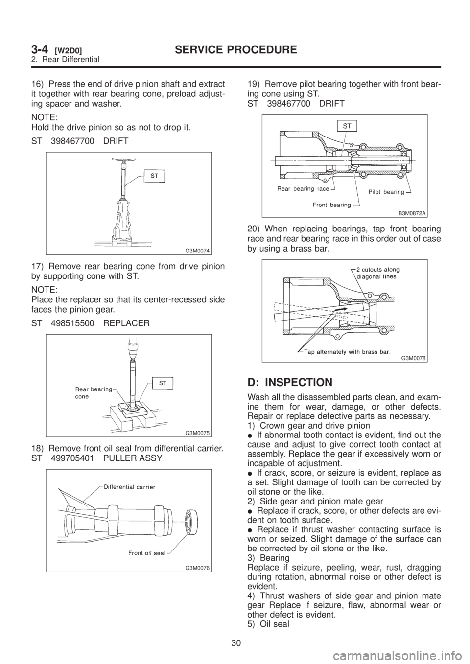
16) Remove front oil seal from differential carrier
using ST.
ST 398527700 PULLER ASSY
G3M0076
17) Remove pilot bearing together with front bear-
ing cone using ST.
ST 398467700 DRIFT
B3M0872A
18) When replacing bearings, tap front bearing
cup and rear bearing cup in this order out of case
by using a brass bar.
G3M0078
2. VA-TYPE
To detect real cause of trouble, inspect the follow-
ing items before disassembling.
ITooth contact of crown gear and pinion, and
backlash
IRunout of crown gear at its back surface
ITurning resistance of drive pinion1) Set ST on vise and install the differential
assembly to ST.
ST 398217700 ATTACHMENT
G3M0060
2) Drain gear oil by removing plug.
3) Remove rear cover by loosening retaining
bolts.
G3M0061
4) Replace air breather cap.
NOTE:
Do not attempt to replace the air breather cap
unless necessary.
G3M0062
27
[W2C2]3-4SERVICE PROCEDURE
2. Rear Differential
Page 678 of 1456
5) Remove right and left lock plates.
G3M0063
6) Remove right and left holders with ST.
ST 399780111 WRENCH
G3M0064
7) Pull out differential assembly from differential
carrier.
CAUTION:
Be careful not to hit the teeth against the case.
G3M0065
8) Remove bearing race from right and left holders
with ST1 and ST2.
ST1 499705401 BEARING OUTER RACE
PULLER ASSY
ST2 499705404 OUTER RACE PULLER
SEAT
G3M0066
9) Remove oil seal from right and left holders with
screwdriver.
CAUTION:
Perform this operation only when changing oil
seal.
B3M0132
28
3-4[W2C2]SERVICE PROCEDURE
2. Rear Differential
Page 679 of 1456
10) Extract bearing cone with ST.
CAUTION:
Do not attempt to disassemble the parts unless
necessary.
NOTE:
ISet Puller so that its claws catch the edge of the
bearing cone.
INever mix up the right and left hand bearing
cones.
ST 899524100 PULLER SET
G3M0068
11) Remove crown gear by loosening crown gear
bolts.
G3M0069
12) Drive out pinion shaft lock pin from crown gear
side.
NOTE:
The lock pin is staked at the pin hole end on the
differential case; do not drive it out forcibly before
unstaking it.
ST 899904100 STRAIGHT PIN REMOVER
B3M0133
13) Draw out pinion mate shaft and remove pinion
mate gears, side gears and thrust washers.
NOTE:
The gears as well as thrust washers should be
marked or kept separated left and right, and front
and rear.
G3M0071
14) Hold companion flange with ST and remove
drive pinion nut.
ST 498427200 FLANGE WRENCH
G3M0072
15) Extract the companion flange with a puller.
G3M0073
29
[W2C2]3-4SERVICE PROCEDURE
2. Rear Differential
Page 680 of 1456

16) Press the end of drive pinion shaft and extract
it together with rear bearing cone, preload adjust-
ing spacer and washer.
NOTE:
Hold the drive pinion so as not to drop it.
ST 398467700 DRIFT
G3M0074
17) Remove rear bearing cone from drive pinion
by supporting cone with ST.
NOTE:
Place the replacer so that its center-recessed side
faces the pinion gear.
ST 498515500 REPLACER
G3M0075
18) Remove front oil seal from differential carrier.
ST 499705401 PULLER ASSY
G3M0076
19) Remove pilot bearing together with front bear-
ing cone using ST.
ST 398467700 DRIFT
B3M0872A
20) When replacing bearings, tap front bearing
race and rear bearing race in this order out of case
by using a brass bar.
G3M0078
D: INSPECTION
Wash all the disassembled parts clean, and exam-
ine them for wear, damage, or other defects.
Repair or replace defective parts as necessary.
1) Crown gear and drive pinion
IIf abnormal tooth contact is evident, find out the
cause and adjust to give correct tooth contact at
assembly. Replace the gear if excessively worn or
incapable of adjustment.
IIf crack, score, or seizure is evident, replace as
a set. Slight damage of tooth can be corrected by
oil stone or the like.
2) Side gear and pinion mate gear
IReplace if crack, score, or other defects are evi-
dent on tooth surface.
IReplace if thrust washer contacting surface is
worn or seized. Slight damage of the surface can
be corrected by oil stone or the like.
3) Bearing
Replace if seizure, peeling, wear, rust, dragging
during rotation, abnormal noise or other defect is
evident.
4) Thrust washers of side gear and pinion mate
gear Replace if seizure, flaw, abnormal wear or
other defect is evident.
5) Oil seal
30
3-4[W2D0]SERVICE PROCEDURE
2. Rear Differential
Page 681 of 1456

Replace if deformed or damaged, and at every
disassembling.
6) Differential carrier
Replace if the bearing bores are worn or damaged.
7) Differential case
Replace if its sliding surfaces are worn or cracked.
8) Companion flange
Replace if the oil seal lip contacting surfaces have
flaws.
E: ASSEMBLY
1. T-TYPE
1) Precautions for assembling
IAssemble in the reverse order of disassembling.
ICheck and adjust each part during assembly.
IKeep the shims and washers in order, so that
they are not misinstalled.
IThoroughly clean the surfaces on which the
shims, washers and bearings are to be installed.
IApply gear oil when installing the bearings and
thrust washers.
IBe careful not to mix up the right and left hand
races of the bearings.
IReplace the oil seal with new one at every dis-
assembly. Apply chassis grease between the lips
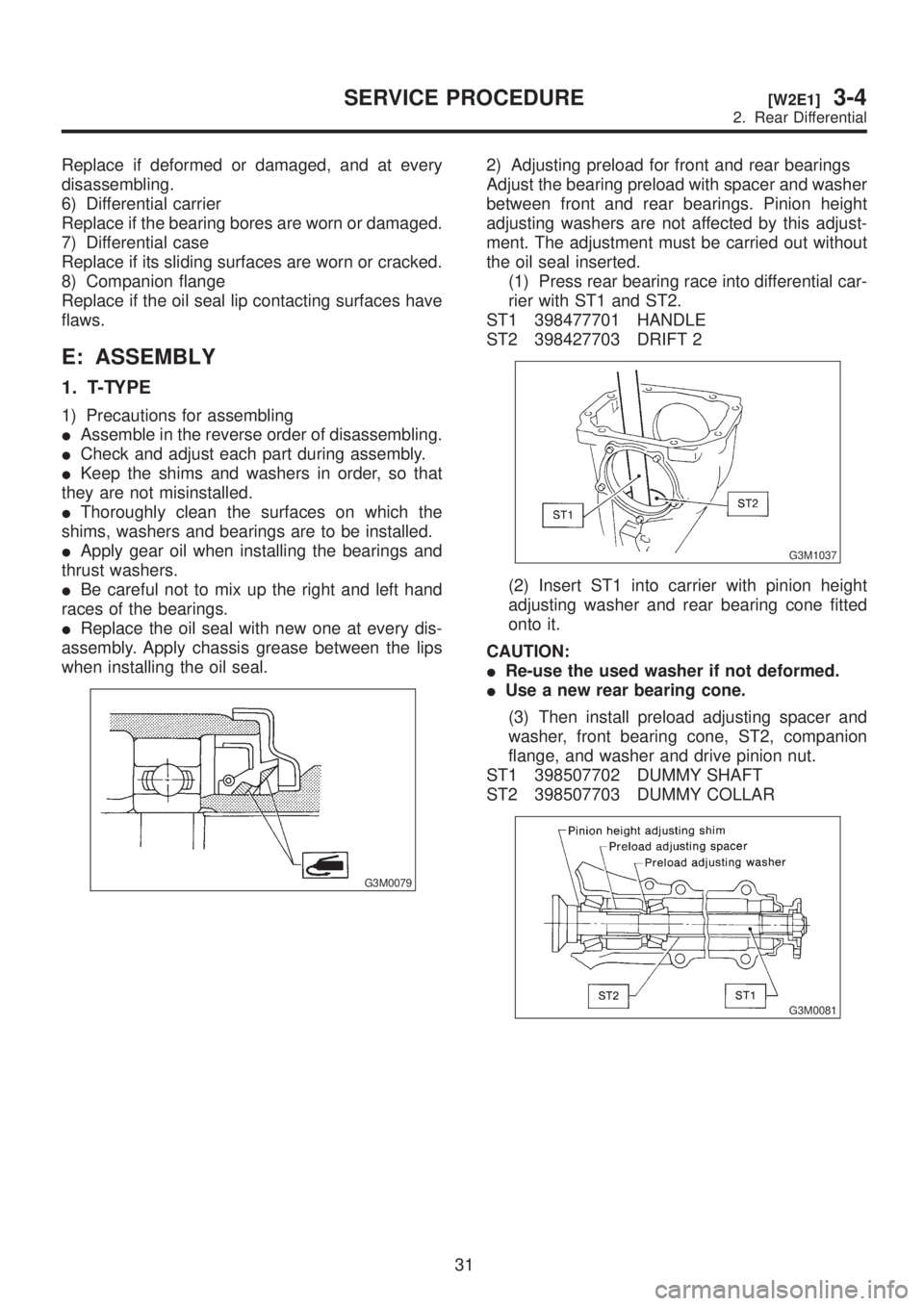
when installing the oil seal.
G3M0079
2) Adjusting preload for front and rear bearings
Adjust the bearing preload with spacer and washer
between front and rear bearings. Pinion height
adjusting washers are not affected by this adjust-
ment. The adjustment must be carried out without
the oil seal inserted.
(1) Press rear bearing race into differential car-
rier with ST1 and ST2.
ST1 398477701 HANDLE
ST2 398427703 DRIFT 2
G3M1037
(2) Insert ST1 into carrier with pinion height
adjusting washer and rear bearing cone fitted
onto it.
CAUTION:
IRe-use the used washer if not deformed.
IUse a new rear bearing cone.
(3) Then install preload adjusting spacer and
washer, front bearing cone, ST2, companion
flange, and washer and drive pinion nut.
ST1 398507702 DUMMY SHAFT
ST2 398507703 DUMMY COLLAR
G3M0081
31
[W2E1]3-4SERVICE PROCEDURE
2. Rear Differential
Page 682 of 1456

(4) Turn ST1 with hand to make it seated, and
tighten drive pinion nut while measuring the pre-
load with spring balance. Select preload adjust-
ing washer and spacer so that the specified pre-
load is obtained when nut is tightened to the
specified torque with ST2.
ST1 398507704 BLOCK
ST2 398507702 DUMMY SHAFT
CAUTION:
Use a new lock nut.
NOTE:
IBe careful not to give excessive preload.
IWhen tightening the drive pinion nut, lock ST1
with ST2 as shown in the figure.
Tightening torque:
181
±15 N´m (18.5±1.5 kg-m, 134±11 ft-lb)
G3M1038
Front and rear bearing preload
For new bearing:
17.7 Ð 25.5 N (1.8 Ð 2.6 kg, 4.0 Ð 5.7 lb)
at companion flange bolt hole
G3M0082
Preload adjusting
washerPart No. Thickness mm (in)
383705200 2.59 (0.1020)
383715200 2.57 (0.1012)
383725200 2.55 (0.1004)
383735200 2.53 (0.0996)
383745200 2.51 (0.0988)
383755200 2.49 (0.0980)
383765200 2.47 (0.0972)
383775200 2.45 (0.0965)
383785200 2.43 (0.0957)
383795200 2.41 (0.0949)
383805200 2.39 (0.0941)
383815200 2.37 (0.0933)
383825200 2.35 (0.0925)
383835200 2.33 (0.0917)
383845200 2.31 (0.0909)
Preload adjusting
spacerPart No. Length mm (in)
383695201 56.2 (2.213)
383695202 56.4 (2.220)
383695203 56.6 (2.228)
383695204 56.8 (2.236)
383695205 57.0 (2.244)
383695206 57.2 (2.252)
3) Adjusting drive pinion height
Adjust drive pinion height with shim installed
between rear bearing cone and the back of pinion
gear.
32
3-4[W2E1]SERVICE PROCEDURE
2. Rear Differential