Page 353 of 1456
9) Take out ECM.
B2M0679A
10) Installation is in the reverse order of removal.
16. Main Relay
A: REMOVAL AND INSTALLATION
1) Disconnect battery ground cable.
G6M0095
2) Remove lower cover and then disconnect con-
nectors.
B5M0024A
3) Lower transmission control module.
4) Remove the front pillar lower trim.
5) Remove fuse box mounting nuts.
6) Lower fuse box.
7) Remove fuse box mounting bracket.
8) Remove screw which retains bracket of main
relay and fuel pump relay.
B2M1191
87
[W16A0]2-7SERVICE PROCEDURE
16. Main Relay
Page 354 of 1456
17. Fuel Pump Relay
A: REMOVAL AND INSTALLATION
1) Disconnect battery ground cable.
G6M0095
2) Remove lower cover and then disconnect con-
nectors.
B5M0024A
3) Lower transmission control module.
4) Remove the front pillar lower trim.
5) Remove fuse box mounting nuts.
6) Lower fuse box.
7) Remove fuse box mounting bracket.
8) Remove fuel pump relay (A) from main relay
and fuel pump relay mounting bracket.
B2M1192D
(A) Fuel pump relay
(B) Main relay
9) Disconnect connector from fuel pump relay.
B2M1192D
(A) Fuel pump relay
(B) Main relay
10) Installation is in the reverse order of removal.
88
2-7[W17A0]SERVICE PROCEDURE
17. Fuel Pump Relay
Page 978 of 1456
1. Air Conditioning System
B4M0757B
(1) Receiver drier bracket
(2) Pipe (Receiver drier Ð Evapora-
tor unit)
(3) Receiver drier
(4) Evaporator unit
(5) Hose (Low-pressure)
(6) A/C relay(7) Fuse
(8) Hose (High-pressure)
(9) Compressor
(10) Condenser
(11) Pipe (Condenser-Receiver drier)Tightening torque: N´m (kg-m, ft-lb)
T1:
7.4±2.0 (0.75±0.2, 5.4±1.4)
T2:15±5 (1.5±0.5, 10.8±3.6)
T3:15±3 (1.5±0.3, 10.8±2.2)
T4:25±5 (2.5±0.5, 18.1±3.6)
4
4-7[C100]COMPONENT PARTS
1. Air Conditioning System
Page 1012 of 1456
17. Relay and Fuse
A: LOCATION
Relays used with A/C system are located as shown
in figure.
IA/C relay
IMain fan (radiator fan) relay
ISub fan (condenser fan) relay
ISub fan (condenser fan) water temperature
relay
IFuses (10 A and 20 A)
G4M0649
B: INSPECTION
1) Check conduction with a circuit tester (ohm
range) according to the following table in figure.
G4M0651
2) Replace relays which do not meet specifica-
tions.
B4M0105A
32
4-7[W17A0]SERVICE PROCEDURE
17. Relay and Fuse
Page 1086 of 1456

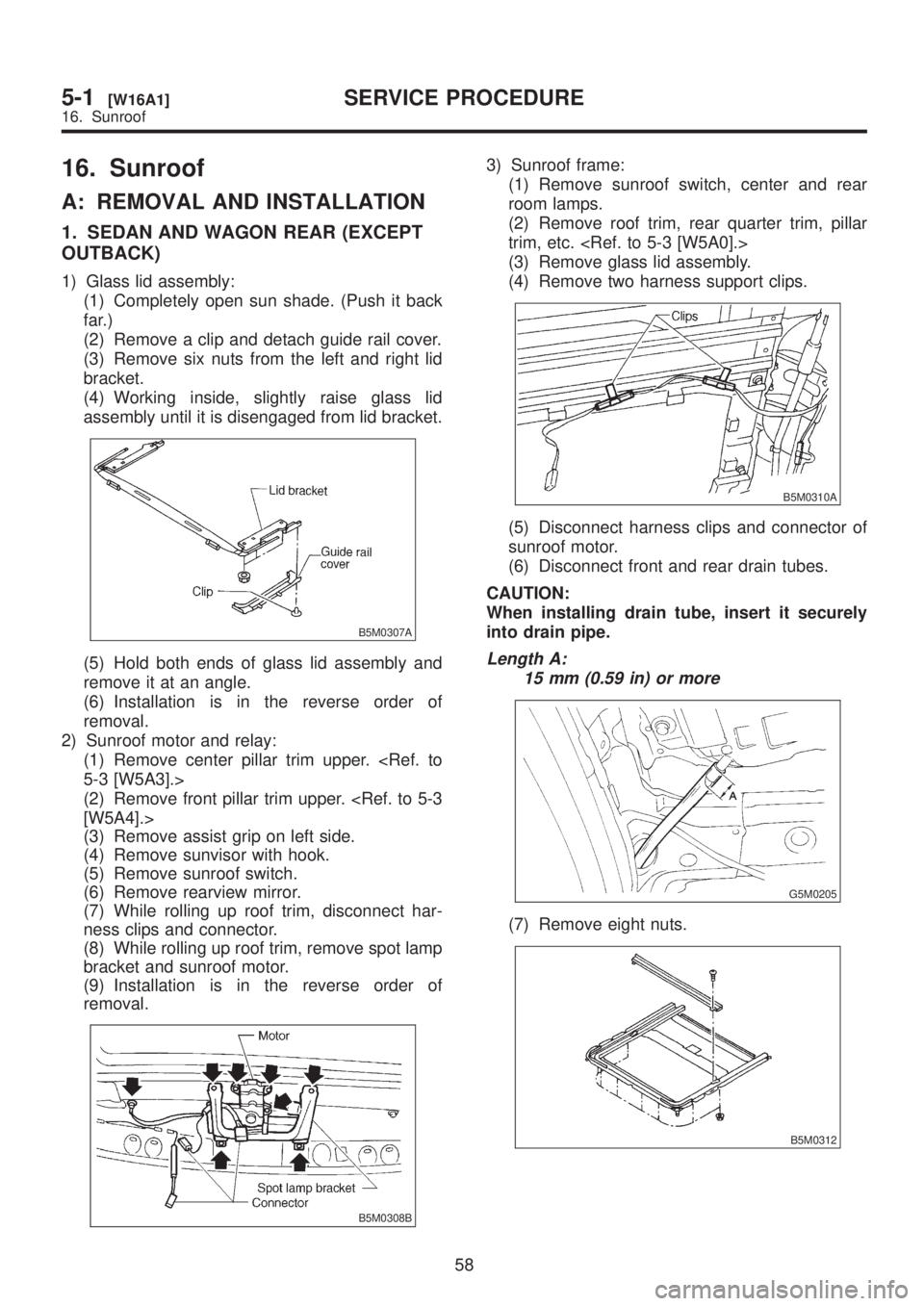
16. Sunroof
A: REMOVAL AND INSTALLATION
1. SEDAN AND WAGON REAR (EXCEPT
OUTBACK)
1) Glass lid assembly:
(1) Completely open sun shade. (Push it back
far.)
(2) Remove a clip and detach guide rail cover.
(3) Remove six nuts from the left and right lid
bracket.
(4) Working inside, slightly raise glass lid
assembly until it is disengaged from lid bracket.
B5M0307A
(5) Hold both ends of glass lid assembly and
remove it at an angle.
(6) Installation is in the reverse order of
removal.
2) Sunroof motor and relay:
(1) Remove center pillar trim upper.
5-3 [W5A3].>
(2) Remove front pillar trim upper.
[W5A4].>
(3) Remove assist grip on left side.
(4) Remove sunvisor with hook.
(5) Remove sunroof switch.
(6) Remove rearview mirror.
(7) While rolling up roof trim, disconnect har-
ness clips and connector.
(8) While rolling up roof trim, remove spot lamp
bracket and sunroof motor.
(9) Installation is in the reverse order of
removal.
B5M0308B
3) Sunroof frame:
(1) Remove sunroof switch, center and rear
room lamps.
(2) Remove roof trim, rear quarter trim, pillar
trim, etc.
(3) Remove glass lid assembly.
(4) Remove two harness support clips.
B5M0310A
(5) Disconnect harness clips and connector of
sunroof motor.
(6) Disconnect front and rear drain tubes.
CAUTION:
When installing drain tube, insert it securely
into drain pipe.
Length A:
15 mm (0.59 in) or more
G5M0205
(7) Remove eight nuts.
B5M0312
58
5-1[W16A1]SERVICE PROCEDURE
16. Sunroof
Page 1099 of 1456

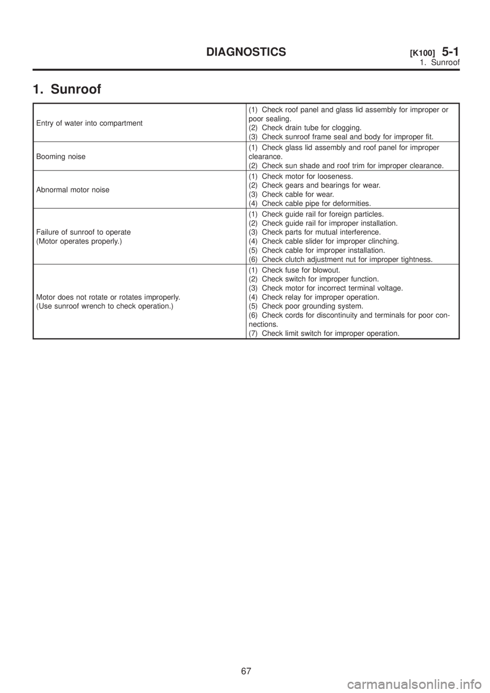
1. Sunroof
Entry of water into compartment(1) Check roof panel and glass lid assembly for improper or
poor sealing.
(2) Check drain tube for clogging.
(3) Check sunroof frame seal and body for improper fit.
Booming noise(1) Check glass lid assembly and roof panel for improper
clearance.
(2) Check sun shade and roof trim for improper clearance.
Abnormal motor noise(1) Check motor for looseness.
(2) Check gears and bearings for wear.
(3) Check cable for wear.
(4) Check cable pipe for deformities.
Failure of sunroof to operate
(Motor operates properly.)(1) Check guide rail for foreign particles.
(2) Check guide rail for improper installation.
(3) Check parts for mutual interference.
(4) Check cable slider for improper clinching.
(5) Check cable for improper installation.
(6) Check clutch adjustment nut for improper tightness.
Motor does not rotate or rotates improperly.
(Use sunroof wrench to check operation.)(1) Check fuse for blowout.
(2) Check switch for improper function.
(3) Check motor for incorrect terminal voltage.
(4) Check relay for improper operation.
(5) Check poor grounding system.
(6) Check cords for discontinuity and terminals for poor con-
nections.
(7) Check limit switch for improper operation.
67
[K100]5-1DIAGNOSTICS
1. Sunroof
Page 1233 of 1456
D: INSPECTION
1. COMBINATION SWITCH (ON-CAR)
1) Remove instrument panel lower cover.
2) Remove lower column cover.
3) Unfasten holddown clip which secures harness, and disconnect connectors from body harness.
4) Move combination switch to respective positions and check continuity between terminals.
B6M0698
2. HEADLIGHT RELAY
Check continuity between terminals as indicated in
table, when connecting the battery to terminal No.
1 and No. 3.
When current
flows.Between terminals
No. 2 and No. 4Continuity exists.
When current
does not flow.Between terminals
No. 2 and No. 4Continuity does not
exist.
Between terminals
No. 1 and No. 3Continuity exists.
8
6-2[W4D1]SERVICE PROCEDURE
4. Headlight
Page 1234 of 1456
G6M0111
3. DAYTIME RUNNING LIGHT RELAY
Check continuity between terminals (indicated in
table) when terminal No. 1 is connected to battery
and terminal No. 2 is grounded.
When current
flows.Between terminals
No. 3 and No. 4Continuity exists.
When current
does not flow.Between terminals
No. 3 and No. 4Continuity does not
exist.
Between terminals
No. 1 and No. 2Continuity exists.
G6M0113
9
[W4D3]6-2SERVICE PROCEDURE
4. Headlight