1999 SUBARU LEGACY relay
[x] Cancel search: relayPage 1282 of 1456
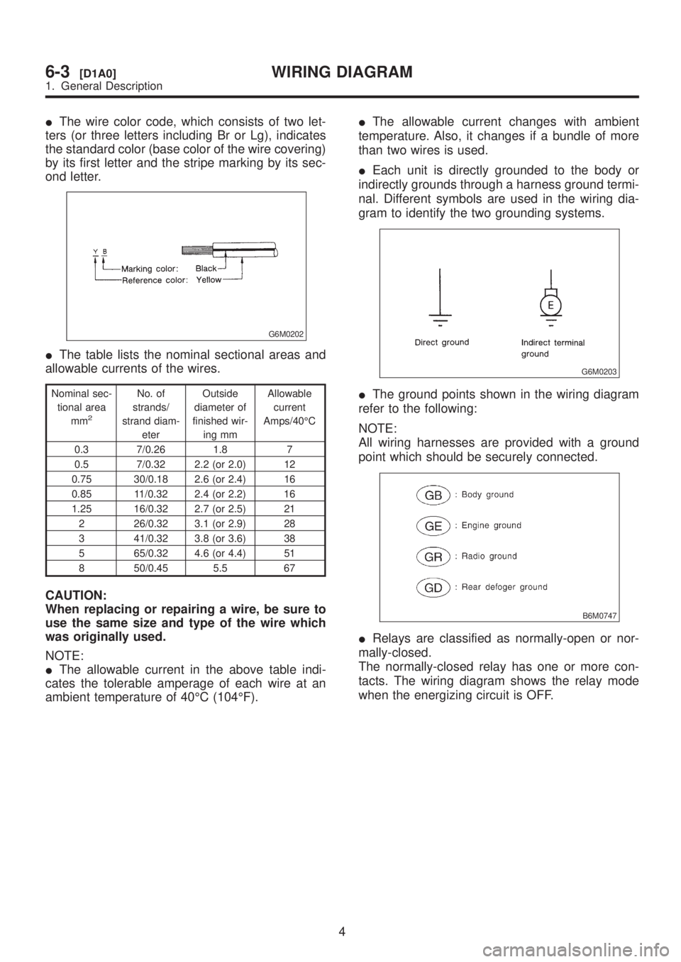
IThe wire color code, which consists of two let-
ters (or three letters including Br or Lg), indicates
the standard color (base color of the wire covering)
by its first letter and the stripe marking by its sec-
ond letter.
G6M0202
IThe table lists the nominal sectional areas and
allowable currents of the wires.
Nominal sec-
tional area
mm
2
No. of
strands/
strand diam-
eterOutside
diameter of
finished wir-
ing mmAllowable
current
Amps/40ÉC
0.3 7/0.26 1.8 7
0.5 7/0.32 2.2 (or 2.0) 12
0.75 30/0.18 2.6 (or 2.4) 16
0.85 11/0.32 2.4 (or 2.2) 16
1.25 16/0.32 2.7 (or 2.5) 21
2 26/0.32 3.1 (or 2.9) 28
3 41/0.32 3.8 (or 3.6) 38
5 65/0.32 4.6 (or 4.4) 51
8 50/0.45 5.5 67
CAUTION:
When replacing or repairing a wire, be sure to
use the same size and type of the wire which
was originally used.
NOTE:
IThe allowable current in the above table indi-
cates the tolerable amperage of each wire at an
ambient temperature of 40ÉC (104ÉF).IThe allowable current changes with ambient
temperature. Also, it changes if a bundle of more
than two wires is used.
IEach unit is directly grounded to the body or
indirectly grounds through a harness ground termi-
nal. Different symbols are used in the wiring dia-
gram to identify the two grounding systems.
G6M0203
IThe ground points shown in the wiring diagram
refer to the following:
NOTE:
All wiring harnesses are provided with a ground
point which should be securely connected.
B6M0747
IRelays are classified as normally-open or nor-
mally-closed.
The normally-closed relay has one or more con-
tacts. The wiring diagram shows the relay mode
when the energizing circuit is OFF.
4
6-3[D1A0]WIRING DIAGRAM
1. General Description
Page 1284 of 1456
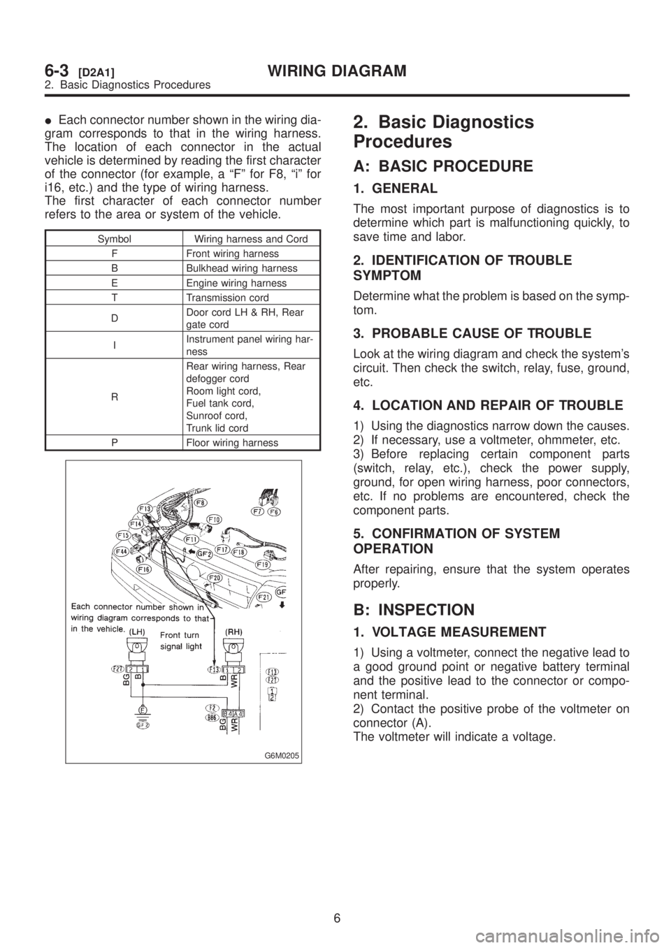
IEach connector number shown in the wiring dia-
gram corresponds to that in the wiring harness.
The location of each connector in the actual
vehicle is determined by reading the first character
of the connector (for example, a ªFº for F8, ªiº for
i16, etc.) and the type of wiring harness.
The first character of each connector number
refers to the area or system of the vehicle.
Symbol Wiring harness and Cord
F Front wiring harness
B Bulkhead wiring harness
E Engine wiring harness
T Transmission cord
DDoor cord LH & RH, Rear
gate cord
IInstrument panel wiring har-
ness
RRear wiring harness, Rear
defogger cord
Room light cord,
Fuel tank cord,
Sunroof cord,
Trunk lid cord
P Floor wiring harness
G6M0205
2. Basic Diagnostics
Procedures
A: BASIC PROCEDURE
1. GENERAL
The most important purpose of diagnostics is to
determine which part is malfunctioning quickly, to
save time and labor.
2. IDENTIFICATION OF TROUBLE
SYMPTOM
Determine what the problem is based on the symp-
tom.
3. PROBABLE CAUSE OF TROUBLE
Look at the wiring diagram and check the system's
circuit. Then check the switch, relay, fuse, ground,
etc.
4. LOCATION AND REPAIR OF TROUBLE
1) Using the diagnostics narrow down the causes.
2) If necessary, use a voltmeter, ohmmeter, etc.
3) Before replacing certain component parts
(switch, relay, etc.), check the power supply,
ground, for open wiring harness, poor connectors,
etc. If no problems are encountered, check the
component parts.
5. CONFIRMATION OF SYSTEM
OPERATION
After repairing, ensure that the system operates
properly.
B: INSPECTION
1. VOLTAGE MEASUREMENT
1) Using a voltmeter, connect the negative lead to
a good ground point or negative battery terminal
and the positive lead to the connector or compo-
nent terminal.
2) Contact the positive probe of the voltmeter on
connector (A).
The voltmeter will indicate a voltage.
6
6-3[D2A1]WIRING DIAGRAM
2. Basic Diagnostics Procedures
Page 1285 of 1456
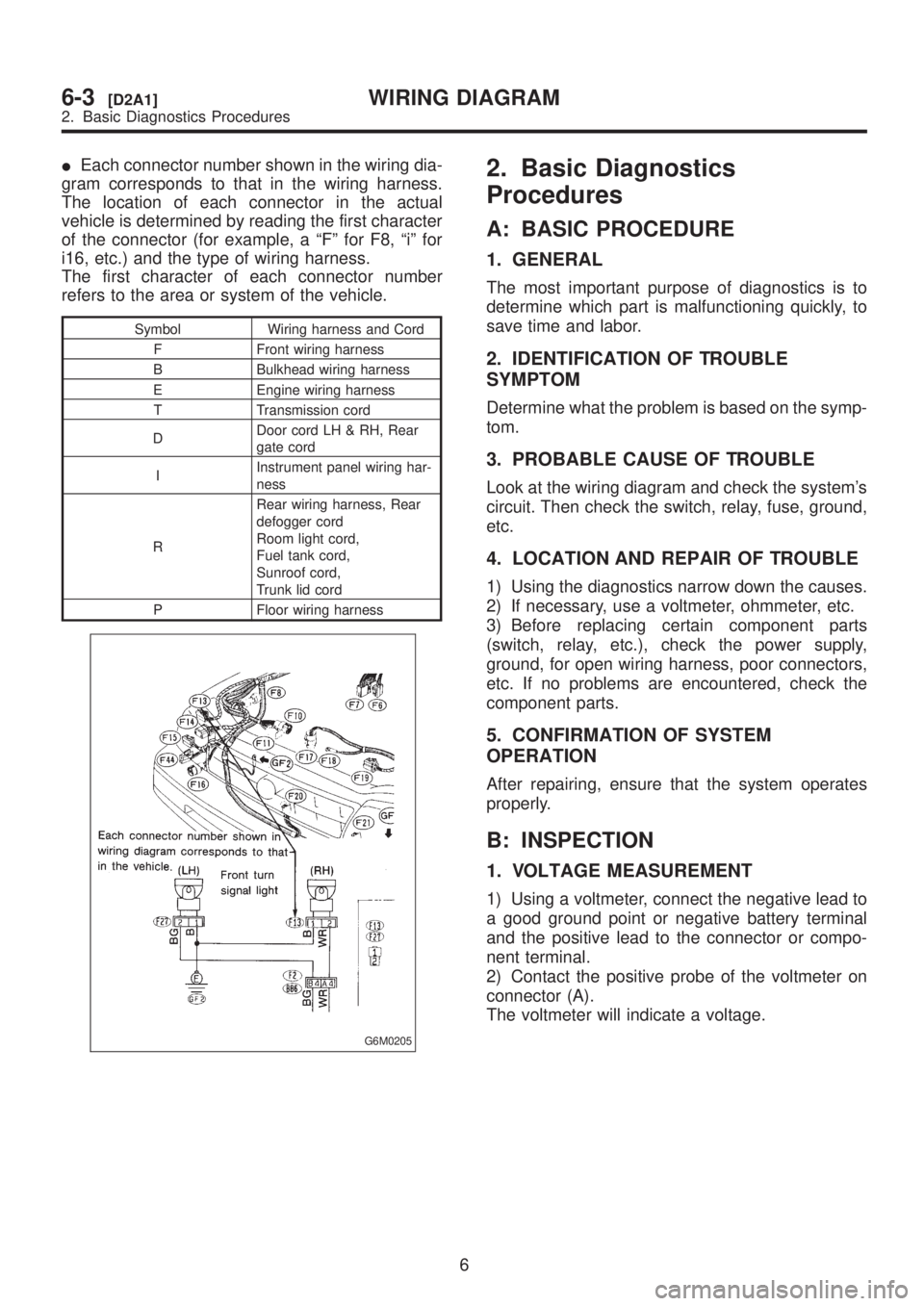
IEach connector number shown in the wiring dia-
gram corresponds to that in the wiring harness.
The location of each connector in the actual
vehicle is determined by reading the first character
of the connector (for example, a ªFº for F8, ªiº for
i16, etc.) and the type of wiring harness.
The first character of each connector number
refers to the area or system of the vehicle.
Symbol Wiring harness and Cord
F Front wiring harness
B Bulkhead wiring harness
E Engine wiring harness
T Transmission cord
DDoor cord LH & RH, Rear
gate cord
IInstrument panel wiring har-
ness
RRear wiring harness, Rear
defogger cord
Room light cord,
Fuel tank cord,
Sunroof cord,
Trunk lid cord
P Floor wiring harness
G6M0205
2. Basic Diagnostics
Procedures
A: BASIC PROCEDURE
1. GENERAL
The most important purpose of diagnostics is to
determine which part is malfunctioning quickly, to
save time and labor.
2. IDENTIFICATION OF TROUBLE
SYMPTOM
Determine what the problem is based on the symp-
tom.
3. PROBABLE CAUSE OF TROUBLE
Look at the wiring diagram and check the system's
circuit. Then check the switch, relay, fuse, ground,
etc.
4. LOCATION AND REPAIR OF TROUBLE
1) Using the diagnostics narrow down the causes.
2) If necessary, use a voltmeter, ohmmeter, etc.
3) Before replacing certain component parts
(switch, relay, etc.), check the power supply,
ground, for open wiring harness, poor connectors,
etc. If no problems are encountered, check the
component parts.
5. CONFIRMATION OF SYSTEM
OPERATION
After repairing, ensure that the system operates
properly.
B: INSPECTION
1. VOLTAGE MEASUREMENT
1) Using a voltmeter, connect the negative lead to
a good ground point or negative battery terminal
and the positive lead to the connector or compo-
nent terminal.
2) Contact the positive probe of the voltmeter on
connector (A).
The voltmeter will indicate a voltage.
6
6-3[D2A1]WIRING DIAGRAM
2. Basic Diagnostics Procedures
Page 1289 of 1456
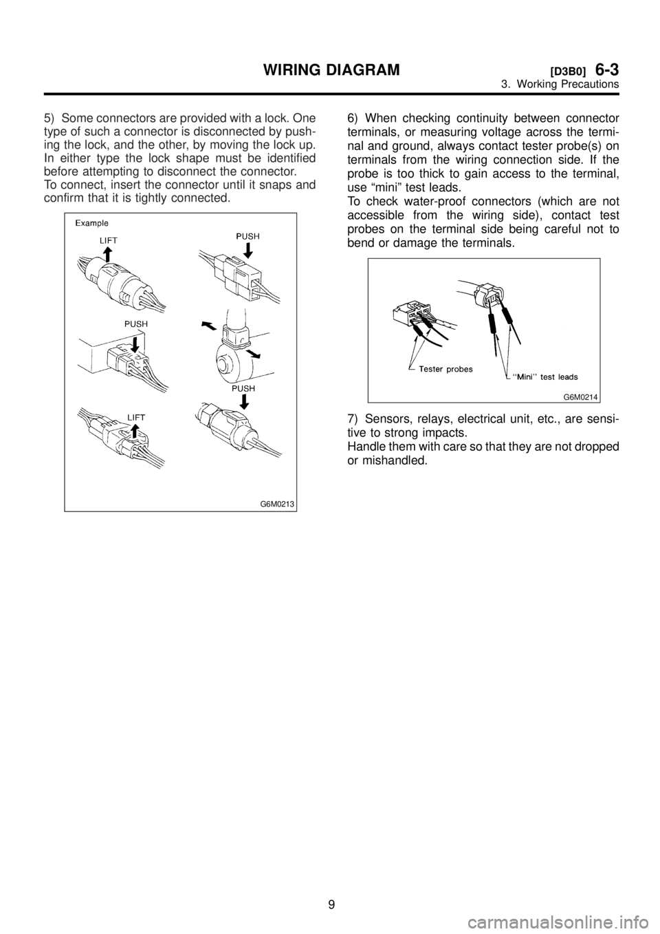
5) Some connectors are provided with a lock. One
type of such a connector is disconnected by push-
ing the lock, and the other, by moving the lock up.
In either type the lock shape must be identified
before attempting to disconnect the connector.
To connect, insert the connector until it snaps and
confirm that it is tightly connected.
G6M0213
6) When checking continuity between connector
terminals, or measuring voltage across the termi-
nal and ground, always contact tester probe(s) on
terminals from the wiring connection side. If the
probe is too thick to gain access to the terminal,
use ªminiº test leads.
To check water-proof connectors (which are not
accessible from the wiring side), contact test
probes on the terminal side being careful not to
bend or damage the terminals.
G6M0214
7) Sensors, relays, electrical unit, etc., are sensi-
tive to strong impacts.
Handle them with care so that they are not dropped
or mishandled.
9
[D3B0]6-3WIRING DIAGRAM
3. Working Precautions
Page 1290 of 1456
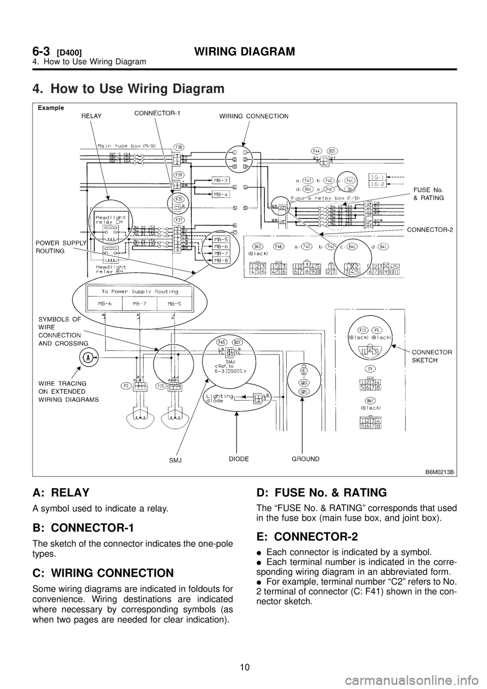
4. How to Use Wiring Diagram
B6M0213B
A: RELAY
A symbol used to indicate a relay.
B: CONNECTOR-1
The sketch of the connector indicates the one-pole
types.
C: WIRING CONNECTION
Some wiring diagrams are indicated in foldouts for
convenience. Wiring destinations are indicated
where necessary by corresponding symbols (as
when two pages are needed for clear indication).
D: FUSE No. & RATING
The ªFUSE No. & RATINGº corresponds that used
in the fuse box (main fuse box, and joint box).
E: CONNECTOR-2
IEach connector is indicated by a symbol.
IEach terminal number is indicated in the corre-
sponding wiring diagram in an abbreviated form.
IFor example, terminal number ªC2º refers to No.
2 terminal of connector (C: F41) shown in the con-
nector sketch.
10
6-3[D400]WIRING DIAGRAM
4. How to Use Wiring Diagram
Page 1296 of 1456
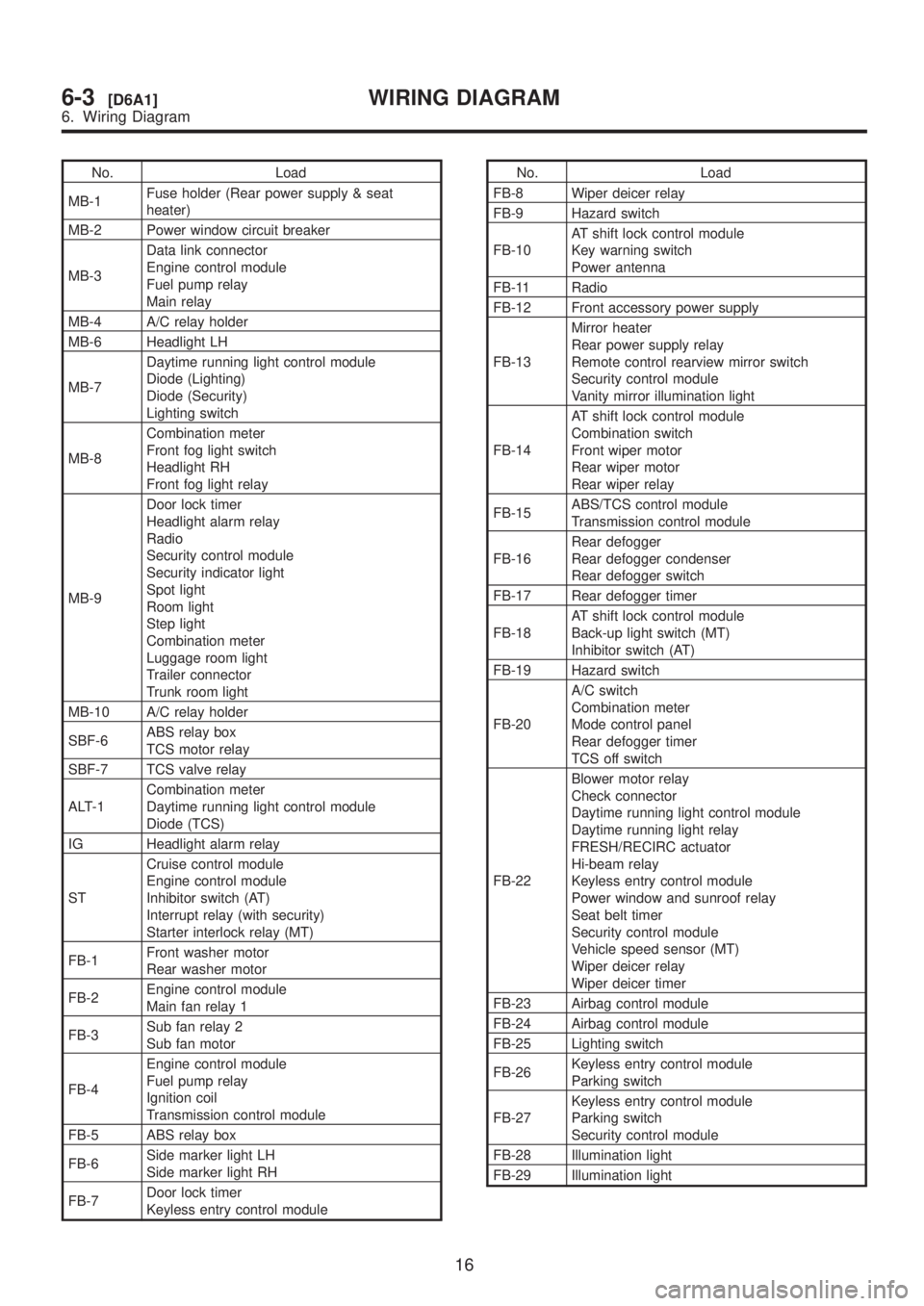
No. Load
MB-1Fuse holder (Rear power supply & seat
heater)
MB-2 Power window circuit breaker
MB-3Data link connector
Engine control module
Fuel pump relay
Main relay
MB-4 A/C relay holder
MB-6 Headlight LH
MB-7Daytime running light control module
Diode (Lighting)
Diode (Security)
Lighting switch
MB-8Combination meter
Front fog light switch
Headlight RH
Front fog light relay
MB-9Door lock timer
Headlight alarm relay
Radio
Security control module
Security indicator light
Spot light
Room light
Step light
Combination meter
Luggage room light
Trailer connector
Trunk room light
MB-10 A/C relay holder
SBF-6ABS relay box
TCS motor relay
SBF-7 TCS valve relay
ALT-1Combination meter
Daytime running light control module
Diode (TCS)
IG Headlight alarm relay
STCruise control module
Engine control module
Inhibitor switch (AT)
Interrupt relay (with security)
Starter interlock relay (MT)
FB-1Front washer motor
Rear washer motor
FB-2Engine control module
Main fan relay 1
FB-3Sub fan relay 2
Sub fan motor
FB-4Engine control module
Fuel pump relay
Ignition coil
Transmission control module
FB-5 ABS relay box
FB-6Side marker light LH
Side marker light RH
FB-7Door lock timer
Keyless entry control moduleNo. Load
FB-8 Wiper deicer relay
FB-9 Hazard switch
FB-10AT shift lock control module
Key warning switch
Power antenna
FB-11 Radio
FB-12 Front accessory power supply
FB-13Mirror heater
Rear power supply relay
Remote control rearview mirror switch
Security control module
Vanity mirror illumination light
FB-14AT shift lock control module
Combination switch
Front wiper motor
Rear wiper motor
Rear wiper relay
FB-15ABS/TCS control module
Transmission control module
FB-16Rear defogger
Rear defogger condenser
Rear defogger switch
FB-17 Rear defogger timer
FB-18AT shift lock control module
Back-up light switch (MT)
Inhibitor switch (AT)
FB-19 Hazard switch
FB-20A/C switch
Combination meter
Mode control panel
Rear defogger timer
TCS off switch
FB-22Blower motor relay
Check connector
Daytime running light control module
Daytime running light relay
FRESH/RECIRC actuator
Hi-beam relay
Keyless entry control module
Power window and sunroof relay
Seat belt timer
Security control module
Vehicle speed sensor (MT)
Wiper deicer relay
Wiper deicer timer
FB-23 Airbag control module
FB-24 Airbag control module
FB-25 Lighting switch
FB-26Keyless entry control module
Parking switch
FB-27Keyless entry control module
Parking switch
Security control module
FB-28 Illumination light
FB-29 Illumination light
16
6-3[D6A1]WIRING DIAGRAM
6. Wiring Diagram
Page 1297 of 1456
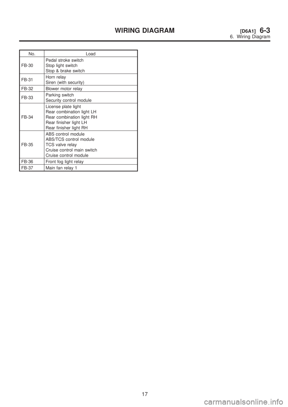
No. Load
FB-30Pedal stroke switch
Stop light switch
Stop & brake switch
FB-31Horn relay
Siren (with security)
FB-32 Blower motor relay
FB-33Parking switch
Security control module
FB-34License plate light
Rear combination light LH
Rear combination light RH
Rear finisher light LH
Rear finisher light RH
FB-35ABS control module
ABS/TCS control module
TCS valve relay
Cruise control main switch
Cruise control module
FB-36 Front fog light relay
FB-37 Main fan relay 1
17
[D6A1]6-3WIRING DIAGRAM
6. Wiring Diagram
Page 1300 of 1456
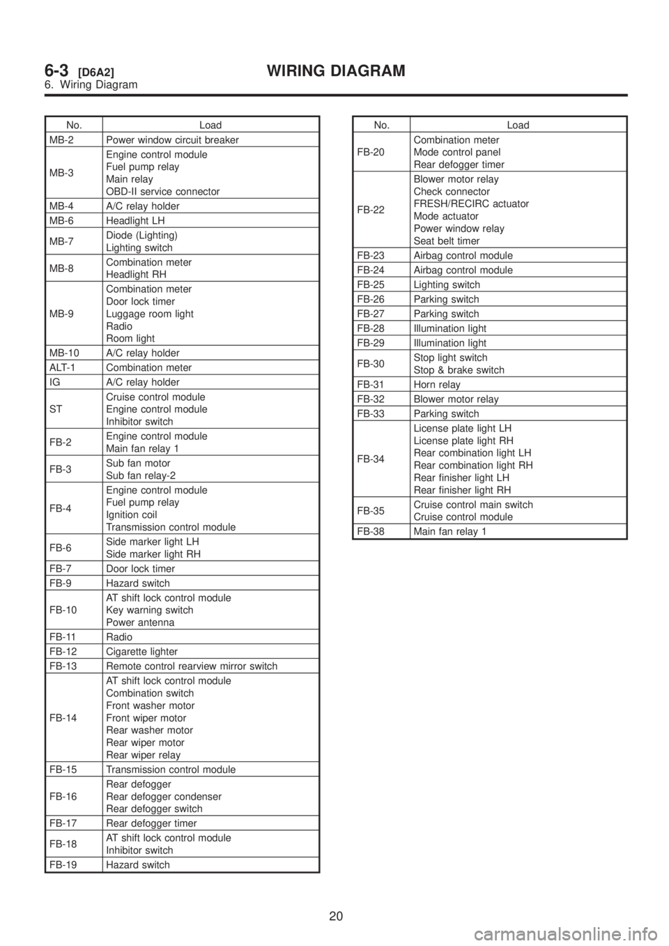
No. Load
MB-2 Power window circuit breaker
MB-3Engine control module
Fuel pump relay
Main relay
OBD-II service connector
MB-4 A/C relay holder
MB-6 Headlight LH
MB-7Diode (Lighting)
Lighting switch
MB-8Combination meter
Headlight RH
MB-9Combination meter
Door lock timer
Luggage room light
Radio
Room light
MB-10 A/C relay holder
ALT-1 Combination meter
IG A/C relay holder
STCruise control module
Engine control module
Inhibitor switch
FB-2Engine control module
Main fan relay 1
FB-3Sub fan motor
Sub fan relay-2
FB-4Engine control module
Fuel pump relay
Ignition coil
Transmission control module
FB-6Side marker light LH
Side marker light RH
FB-7 Door lock timer
FB-9 Hazard switch
FB-10AT shift lock control module
Key warning switch
Power antenna
FB-11 Radio
FB-12 Cigarette lighter
FB-13 Remote control rearview mirror switch
FB-14AT shift lock control module
Combination switch
Front washer motor
Front wiper motor
Rear washer motor
Rear wiper motor
Rear wiper relay
FB-15 Transmission control module
FB-16Rear defogger
Rear defogger condenser
Rear defogger switch
FB-17 Rear defogger timer
FB-18AT shift lock control module
Inhibitor switch
FB-19 Hazard switchNo. Load
FB-20Combination meter
Mode control panel
Rear defogger timer
FB-22Blower motor relay
Check connector
FRESH/RECIRC actuator
Mode actuator
Power window relay
Seat belt timer
FB-23 Airbag control module
FB-24 Airbag control module
FB-25 Lighting switch
FB-26 Parking switch
FB-27 Parking switch
FB-28 Illumination light
FB-29 Illumination light
FB-30Stop light switch
Stop & brake switch
FB-31 Horn relay
FB-32 Blower motor relay
FB-33 Parking switch
FB-34License plate light LH
License plate light RH
Rear combination light LH
Rear combination light RH
Rear finisher light LH
Rear finisher light RH
FB-35Cruise control main switch
Cruise control module
FB-38 Main fan relay 1
20
6-3[D6A2]WIRING DIAGRAM
6. Wiring Diagram