Page 1239 of 1456
IWith TCS Model:
1) Disconnect connector of stop light switch from
body harness.
2) Check continuity between terminals when push
rod is pushed in 1.2 to 3.2 mm (0.047 to 0.126 in)
from end of outer case.
B6M0833A
2. COMBINATION SWITCH (ON-CAR)
Inspect combination switch.
3. TAIL AND ILLUMINATION RELAY
Check continuity between terminals as indicated in
table when connecting battery to terminal No. 1
and No. 3.
When current flows. Between termi-
nals No. 2 and
No. 4Continuity
exists.
When current does not
flow.Between termi-
nals No. 2 and
No. 4Continuity does
not exist.
Between termi-
nals No. 1 and
No. 3Continuity
exists.
G6M0112
13
[W6C3]6-2SERVICE PROCEDURE
6. Stop and Tail Light
Page 1252 of 1456
3) Reconnect battery and ensure that wiper motor
stops at ªAUTO STOPº after it has been operated.
B6M0169
3. REAR WIPER RELAY
1) Connect battery to terminal No. 1 and ground
terminal No. 2.
2) Check continuity between terminals.
When current flows. Between termi-
nals No. 3 and
No. 5Continuity does
not exist.
Between termi-
nals No. 3 and
No. 4Continuity
exists.
When current does not
flow.Between termi-
nals No. 3 and
No. 5Continuity
exists.
Between termi-
nals No. 3 and
No. 4Continuity does
not exist.
Between termi-
nals No. 1 and
No. 2Continuity
exists.
G6M0134
4. WASHER MOTOR
Apply battery voltage between terminals of washer
motor connector and check that washer motor
operates.
B6M0111
24
6-2[W12D3]SERVICE PROCEDURE
12. Rear Wiper and Washer
Page 1253 of 1456
13. Rear Window Defogger
A: REMOVAL AND INSTALLATION
1. DEFOGGER SWITCH
1) Remove screws which secure meter visor.
2) Remove meter visor from instrument panel
while disconnecting connectors.
3) Remove rear window defogger switch from
meter visor.
4) Installation is in the reverse order of removal.
B: INSPECTION
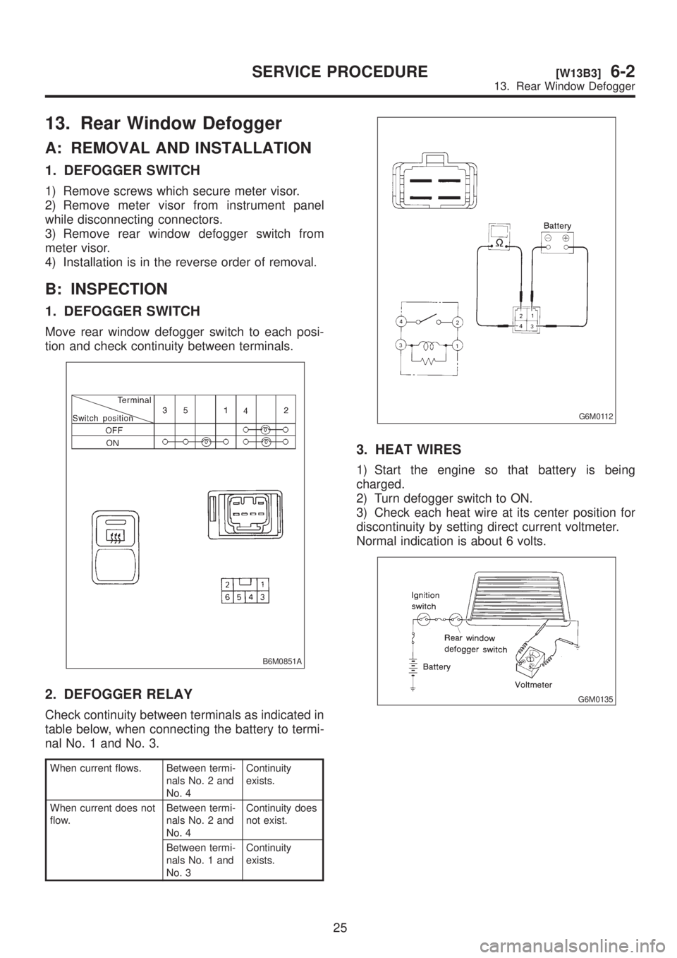
1. DEFOGGER SWITCH
Move rear window defogger switch to each posi-
tion and check continuity between terminals.
B6M0851A
2. DEFOGGER RELAY
Check continuity between terminals as indicated in
table below, when connecting the battery to termi-
nal No. 1 and No. 3.
When current flows. Between termi-
nals No. 2 and
No. 4Continuity
exists.
When current does not
flow.Between termi-
nals No. 2 and
No. 4Continuity does
not exist.
Between termi-
nals No. 1 and
No. 3Continuity
exists.
G6M0112
3. HEAT WIRES
1) Start the engine so that battery is being
charged.
2) Turn defogger switch to ON.
3) Check each heat wire at its center position for
discontinuity by setting direct current voltmeter.
Normal indication is about 6 volts.
G6M0135
25
[W13B3]6-2SERVICE PROCEDURE
13. Rear Window Defogger
Page 1258 of 1456
16. Horn and Cigarette Lighter
A: REMOVAL AND INSTALLATION
1. HORN
1) Open the engine hood.
2) Disconnect connector of horn.
3) Remove the horn.
4) Installation is in the reverse order of removal.
Tightening torque:
18
±5 N´m (1.8±0.5 kg-m, 13.0±3.6 ft-lb)
CAUTION:
After installing horn, connect connector, fit
firmly wiring harness to prevent from discon-
necting due to vibration.
B6M0349
2. HORN SWITCH (HORN PAD)
1) Remove screw which secures horn switch
(steering pad) to the base of steering wheel.
B6M0124
2) Remove horn switch (steering pad) from steer-
ing wheel while disconnecting connector.
3) Installation is in the reverse order of removal.
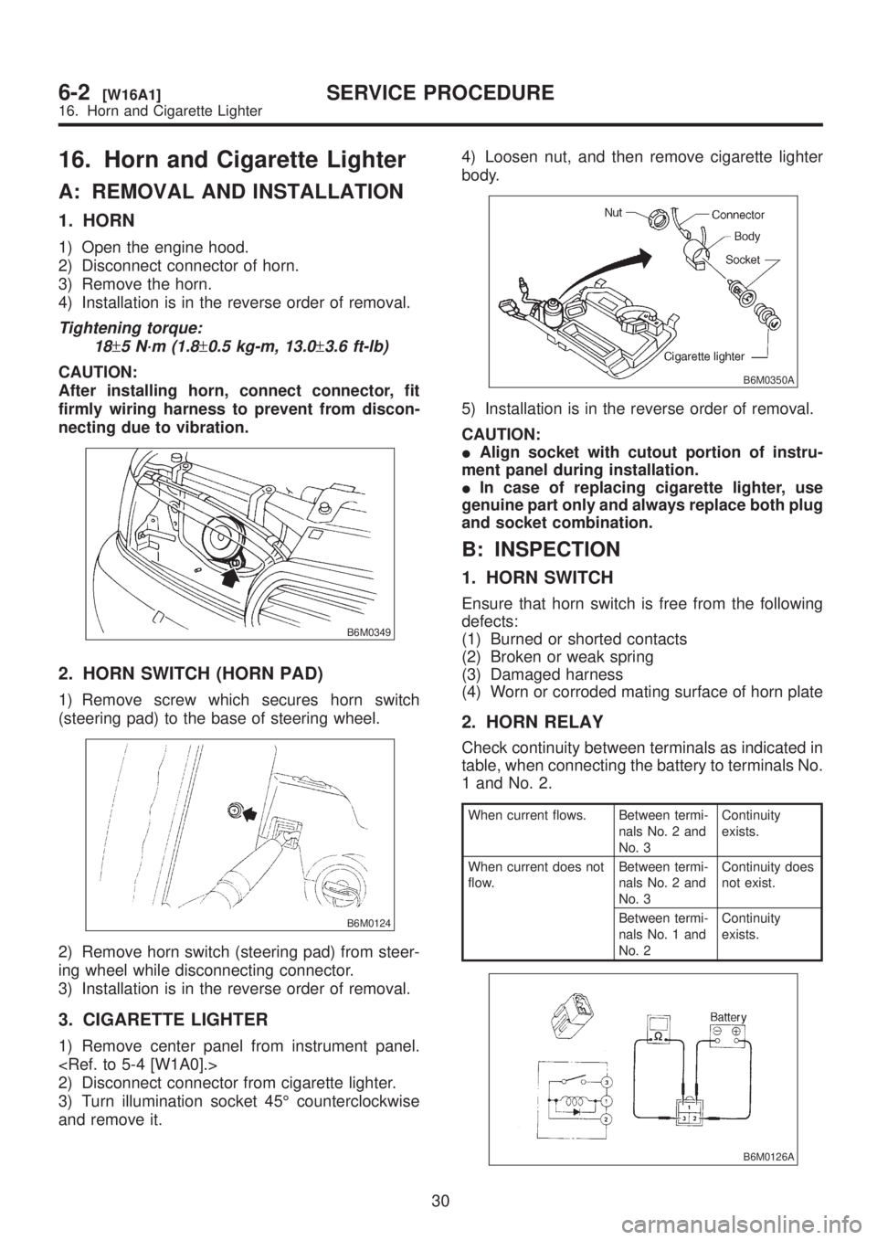
3. CIGARETTE LIGHTER
1) Remove center panel from instrument panel.
2) Disconnect connector from cigarette lighter.
3) Turn illumination socket 45É counterclockwise
and remove it.4) Loosen nut, and then remove cigarette lighter
body.
B6M0350A
5) Installation is in the reverse order of removal.
CAUTION:
IAlign socket with cutout portion of instru-
ment panel during installation.
IIn case of replacing cigarette lighter, use
genuine part only and always replace both plug
and socket combination.
B: INSPECTION
1. HORN SWITCH
Ensure that horn switch is free from the following
defects:
(1) Burned or shorted contacts
(2) Broken or weak spring
(3) Damaged harness
(4) Worn or corroded mating surface of horn plate
2. HORN RELAY
Check continuity between terminals as indicated in
table, when connecting the battery to terminals No.
1 and No. 2.
When current flows. Between termi-
nals No. 2 and
No. 3Continuity
exists.
When current does not
flow.Between termi-
nals No. 2 and
No. 3Continuity does
not exist.
Between termi-
nals No. 1 and
No. 2Continuity
exists.
B6M0126A
30
6-2[W16A1]SERVICE PROCEDURE
16. Horn and Cigarette Lighter
Page 1262 of 1456
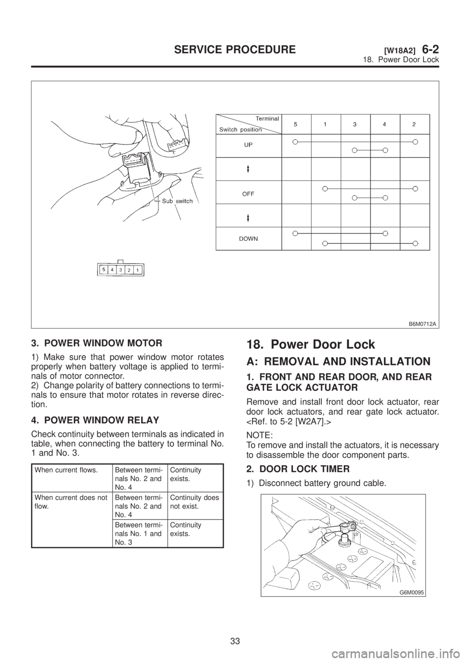
B6M0712A
3. POWER WINDOW MOTOR
1) Make sure that power window motor rotates
properly when battery voltage is applied to termi-
nals of motor connector.
2) Change polarity of battery connections to termi-
nals to ensure that motor rotates in reverse direc-
tion.
4. POWER WINDOW RELAY
Check continuity between terminals as indicated in
table, when connecting the battery to terminal No.
1 and No. 3.
When current flows. Between termi-
nals No. 2 and
No. 4Continuity
exists.
When current does not
flow.Between termi-
nals No. 2 and
No. 4Continuity does
not exist.
Between termi-
nals No. 1 and
No. 3Continuity
exists.
18. Power Door Lock
A: REMOVAL AND INSTALLATION
1. FRONT AND REAR DOOR, AND REAR
GATE LOCK ACTUATOR
Remove and install front door lock actuator, rear
door lock actuators, and rear gate lock actuator.
NOTE:
To remove and install the actuators, it is necessary
to disassemble the door component parts.
2. DOOR LOCK TIMER
1) Disconnect battery ground cable.
G6M0095
33
[W18A2]6-2SERVICE PROCEDURE
18. Power Door Lock
Page 1263 of 1456
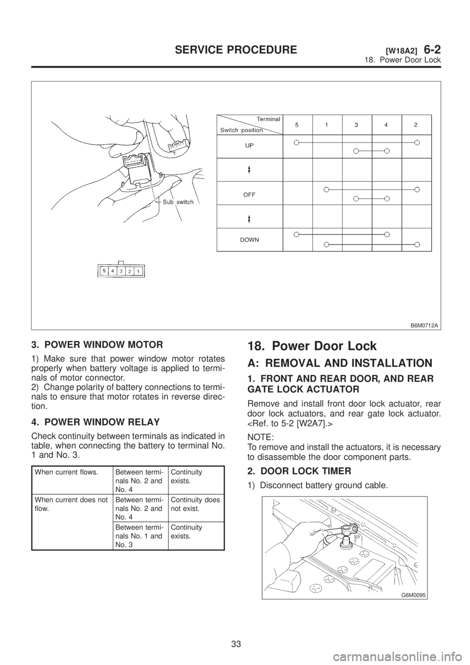
B6M0712A
3. POWER WINDOW MOTOR
1) Make sure that power window motor rotates
properly when battery voltage is applied to termi-
nals of motor connector.
2) Change polarity of battery connections to termi-
nals to ensure that motor rotates in reverse direc-
tion.
4. POWER WINDOW RELAY
Check continuity between terminals as indicated in
table, when connecting the battery to terminal No.
1 and No. 3.
When current flows. Between termi-
nals No. 2 and
No. 4Continuity
exists.
When current does not
flow.Between termi-
nals No. 2 and
No. 4Continuity does
not exist.
Between termi-
nals No. 1 and
No. 3Continuity
exists.
18. Power Door Lock
A: REMOVAL AND INSTALLATION
1. FRONT AND REAR DOOR, AND REAR
GATE LOCK ACTUATOR
Remove and install front door lock actuator, rear
door lock actuators, and rear gate lock actuator.
NOTE:
To remove and install the actuators, it is necessary
to disassemble the door component parts.
2. DOOR LOCK TIMER
1) Disconnect battery ground cable.
G6M0095
33
[W18A2]6-2SERVICE PROCEDURE
18. Power Door Lock
Page 1268 of 1456
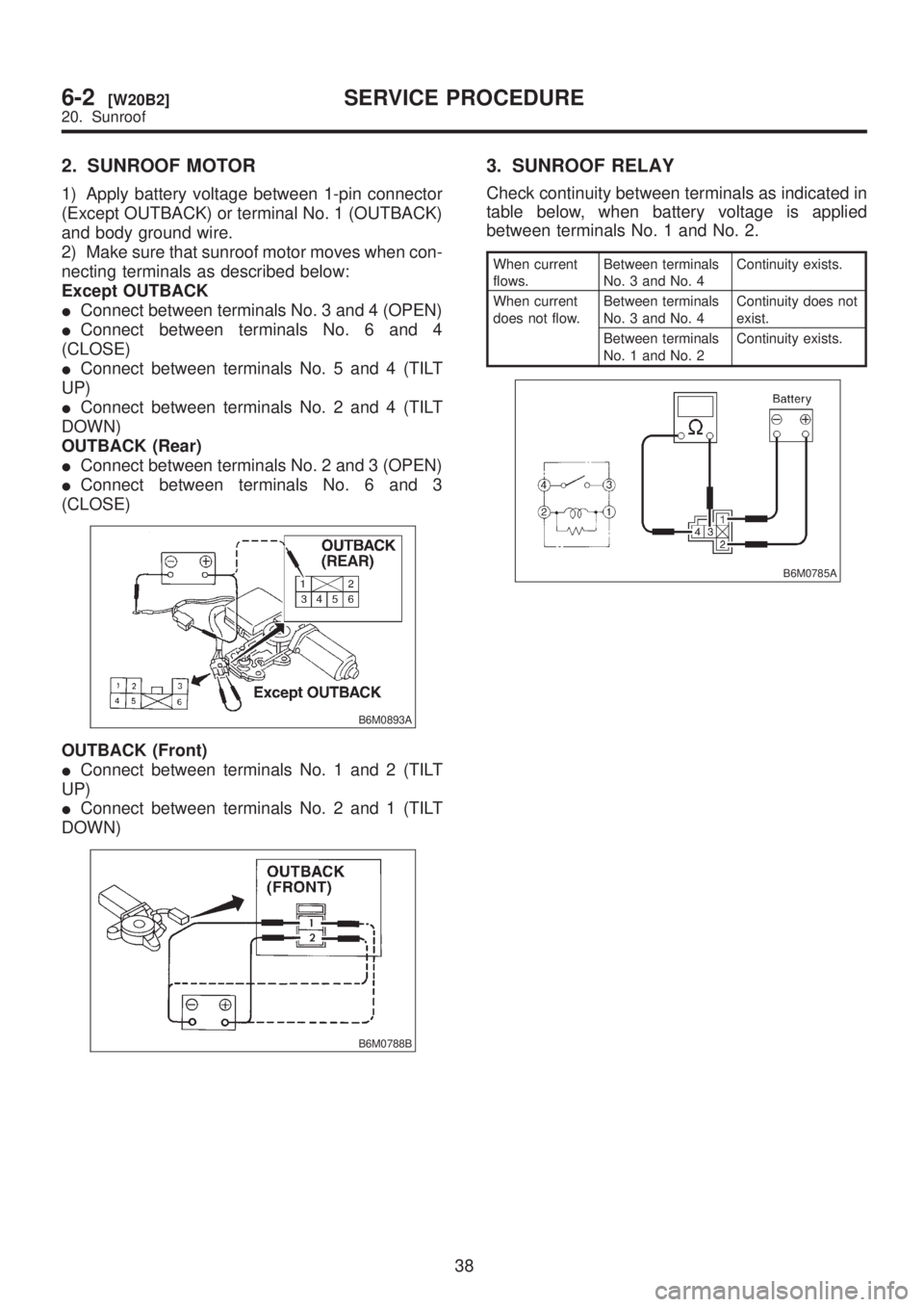
2. SUNROOF MOTOR
1) Apply battery voltage between 1-pin connector
(Except OUTBACK) or terminal No. 1 (OUTBACK)
and body ground wire.
2) Make sure that sunroof motor moves when con-
necting terminals as described below:
Except OUTBACK
IConnect between terminals No. 3 and 4 (OPEN)
IConnect between terminals No. 6 and 4
(CLOSE)
IConnect between terminals No. 5 and 4 (TILT
UP)
IConnect between terminals No. 2 and 4 (TILT
DOWN)
OUTBACK (Rear)
IConnect between terminals No. 2 and 3 (OPEN)
IConnect between terminals No. 6 and 3
(CLOSE)
B6M0893A
OUTBACK (Front)
IConnect between terminals No. 1 and 2 (TILT
UP)
IConnect between terminals No. 2 and 1 (TILT
DOWN)
B6M0788B
3. SUNROOF RELAY
Check continuity between terminals as indicated in
table below, when battery voltage is applied
between terminals No. 1 and No. 2.
When current
flows.Between terminals
No. 3 and No. 4Continuity exists.
When current
does not flow.Between terminals
No. 3 and No. 4Continuity does not
exist.
Between terminals
No. 1 and No. 2Continuity exists.
B6M0785A
38
6-2[W20B2]SERVICE PROCEDURE
20. Sunroof
Page 1277 of 1456
25. Wiper Deicer
A: REMOVAL AND INSTALLATION
1. WIPER DEICER SWITCH
1) Detach console cover while disconnecting con-
nector.
2) Remove wiper deicer switch from console
cover.
B6M0862A
3) Installation is in the rverse order of removal.
B: INSPECTION
1. WIPER DEICER SWITCH
Set switch to each position and check continuity
between terminals.
B6M0892A
2. WIPER DEICER RELAY
Check continuity between terminals as indicated in
table below, when connecting the battery to termi-
nal No. 1 and No. 2.
When current
flows.Between terminals
No. 3 and No. 4Continuity exists.
When current
does not flow.Between terminals
No. 3 and No. 4Continuity does not
exist.
Between terminals
No. 1 and No. 2Continuity exists.
B6M0239A
46
6-2[W25A1]SERVICE PROCEDURE
25. Wiper Deicer