Page 200 of 1456
1) Install baffle plate.
2) Install oil strainer and O-ring.
3) Install oil strainer stay.
4) Apply fluid packing to matching surfaces and
install oil pan.
Fluid packing:
THREE BOND 1215 or equivalent
G2M0084
5) Apply fluid packing to matching surfaces and
install oil separator cover.
Fluid packing:
THREE BOND 1215 or equivalent
G2M0194
6) Install flywheel (MT vehicles only) or drive plate
(AT vehicles only).
To lock crankshaft, use ST.
ST 498497100 CRANKSHAFT STOPPER
G2M0776
B2M0706A
7) Install clutch housing cover. (MT vehicles only)
8) Installation of oil pump
(1) Discard front oil seal after removal. Replace
with a new one by using ST.
ST 499587100 OIL SEAL INSTALLER
S2M0235
69
[W5E1]2-3bSERVICE PROCEDURE
5. Cylinder Block
Page 260 of 1456

1. Engine Cooling System Trouble in General
TroubleCorrective action
Over-heatinga. Insufficient engine coolantReplenish engine coolant, inspect for leakage, and
repair.
b. Loose timing belt Repair or replace timing belt tensioner.
c. Oil on drive belt Replace.
d. Malfunction of thermostat Replace.
e. Malfunction of water pump Replace.
f. Clogged engine coolant passage Clean.
g. Improper ignition timingInspect and repair ignition control system.
On-Board Diagnostics II System
h. Clogged or leaking radiator Clean or repair, or replace.
i. Improper engine oil in engine coolant Replace engine coolant.
j. Air/fuel mixture ratio too leanInspect and repair fuel injection system.
On-Board Diagnostics II System
k. Excessive back pressure in exhaust system Clean or replace.
l. Insufficient clearance between piston and cylinder Adjust or replace.
m. Slipping clutch Repair or replace.
n. Dragging brake Adjust.
o. Improper transmission oil Replace.
p. Defective thermostat Replace.
q. Malfunction of electric fanInspect radiator fan relay, engine coolant temperature
sensor or radiator motor and replace there.
Over-coolinga. Atmospheric temperature extremely low Partly cover radiator front area.
b. Defective thermostat Replace.
Engine coolant
leaks.a. Loosened or damaged connecting units on
hosesRepair or replace.
b. Leakage from water pump Replace.
c. Leakage from water pipe Repair or replace.
d. Leakage around cylinder head gasket Retighten cylinder head bolts or replace gasket.
e. Damaged or cracked cylinder head and crank-
caseRepair or replace.
f. Damaged or cracked thermostat case Repair or replace.
g. Leakage from radiator Repair or replace.
Noisea. Defective drive belt Replace.
b. Defective radiator fan Replace.
c. Defective water pump bearing Replace water pump.
d. Defective water pump mechanical seal Replace water pump.
26
2-5[K100]DIAGNOSTICS
1. Engine Cooling System Trouble in General
Page 411 of 1456
1. Clutch System
2200 cc 2500 cc
Clutch cover Diaphragm set load kg (lb) 450 (992) 550 (1,213)
Clutch discFacing material Woven
O.D.´I.D.´thickness mm (in) 225´150´3.5 (8.86´5.91´0.138)
Spline O.D. (No. of teeth) mm (in) 25.2 (0.992) (24)
Depth of rivet head mm
(in)Standard 1.3 Ð 1.9 (0.051 Ð 0.075)
Limit of sinking 0.3 (0.012)
Limit for runout mm (in) 1.0 (0.039) at R = 107 (4.21)
Clutch release lever ratio 3.0 1.6
Release bearingGrease-packed self-aligning
Release leverStroke mm (in) 24 Ð 26 (0.94 Ð 1.02)
Play at release lever center mm (in)3 Ð 4 (0.12 Ð 0.16)
Clutch pedal Full stroke mm (in)140 Ð 150
(5.51 Ð 5.91)130 Ð 135
(5.12 Ð 5.31)
2
2-10[S100]SPECIFICATIONS AND SERVICE DATA
1. Clutch System
Page 412 of 1456
1. Clutch System
A: MECHANICAL APPLICATION TYPE
B2M0632C
(1) Clutch cable bracket
(2) Clutch release lever sealing
(3) Retainer spring
(4) Pivot
(5) Clutch release lever(6) Clip
(7) Clutch release bearing
(8) Clutch cover
(9) Clutch disc(10) Return spring (Models without
hill holder only)
(11) Clutch return spring bracket
Tightening torque: N´m (kg-m, ft-lb)
T1:
15.7±1.5 (1.6±0.15, 11.6±1.1)
3
[C1A0]2-10COMPONENT PARTS
1. Clutch System
Page 413 of 1456
B: HYDRAULIC APPLICATION TYPE
B2M1890A
(1) Operating cylinder
(2) Washer
(3) Clutch hose
(4) Bracket
(5) Clamp
(6) Pipe
(7) Master cylinder ASSY
(8) Clevis pin
(9) Snap pin(10) Lever
(11) Clutch release lever sealing
(12) Retainer spring
(13) Pivot
(14) Release lever
(15) Clip
(16) Release bearing
(17) Clutch cover
(18) Clutch disc(19) Flywheel
Tightening torque: N´m (kg-m, ft-lb)
T1:
15.7±1.5 (1.6±0.15, 11.6±1.1)
T2:18±3 (1.8±0.3, 13.0±2.2)
T3:37±3 (3.8±0.3, 27.5±2.2)
4
2-10[C1B0]COMPONENT PARTS
1. Clutch System
Page 415 of 1456

1. General
A: PRECAUTION
When servicing clutch system, pay attention to the
following items.
1. MECHANICAL APPLICATION TYPE
1) Check the routing of clutch cable for smooth-
ness.
2) Excessive tightness or looseness of clutch
cable have a bad influence upon the cable durabil-
ity.
3) Apply grease sufficiently to the connecting por-
tion of clutch pedal.
4) Apply grease sufficiently to the release lever
portion.
5) Position clutch cable through the center of toe
board hole and route it smoothly. Adjustment is
done by moving the outer cable.
6) Make sure not to let the clutch chatter when
starting forward or rearward. If clutch chattering
occurs, readjust so that the bend of clutch outer
cable becomes flatter.
2. HYDRAULIC APPLICATION TYPE
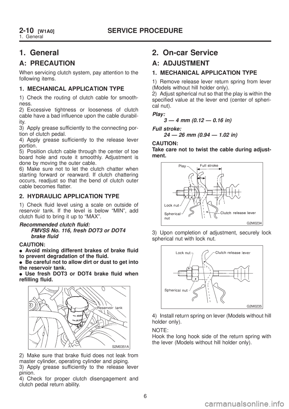
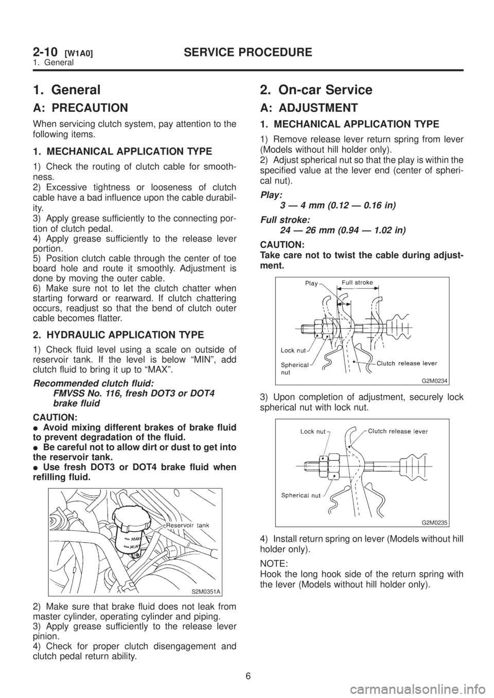
1) Check fluid level using a scale on outside of
reservoir tank. If the level is below ªMINº, add
clutch fluid to bring it up to ªMAXº.
Recommended clutch fluid:
FMVSS No. 116, fresh DOT3 or DOT4
brake fluid
CAUTION:
IAvoid mixing different brakes of brake fluid
to prevent degradation of the fluid.
IBe careful not to allow dirt or dust to get into
the reservoir tank.
IUse fresh DOT3 or DOT4 brake fluid when
refilling fluid.
S2M0351A
2) Make sure that brake fluid does not leak from
master cylinder, operating cylinder and piping.
3) Apply grease sufficiently to the release lever
pinion.
4) Check for proper clutch disengagement and
clutch pedal return ability.
2. On-car Service
A: ADJUSTMENT
1. MECHANICAL APPLICATION TYPE
1) Remove release lever return spring from lever
(Models without hill holder only).
2) Adjust spherical nut so that the play is within the
specified value at the lever end (center of spheri-
cal nut).
Play:
3Ð4mm(0.12 Ð 0.16 in)
Full stroke:
24 Ð 26 mm (0.94 Ð 1.02 in)
CAUTION:
Take care not to twist the cable during adjust-
ment.
G2M0234
3) Upon completion of adjustment, securely lock
spherical nut with lock nut.
G2M0235
4) Install return spring on lever (Models without hill
holder only).
NOTE:
Hook the long hook side of the return spring with
the lever (Models without hill holder only).
6
2-10[W1A0]SERVICE PROCEDURE
1. General
Page 416 of 1456

1. General
A: PRECAUTION
When servicing clutch system, pay attention to the
following items.
1. MECHANICAL APPLICATION TYPE
1) Check the routing of clutch cable for smooth-
ness.
2) Excessive tightness or looseness of clutch
cable have a bad influence upon the cable durabil-
ity.
3) Apply grease sufficiently to the connecting por-
tion of clutch pedal.
4) Apply grease sufficiently to the release lever
portion.
5) Position clutch cable through the center of toe
board hole and route it smoothly. Adjustment is
done by moving the outer cable.
6) Make sure not to let the clutch chatter when
starting forward or rearward. If clutch chattering
occurs, readjust so that the bend of clutch outer
cable becomes flatter.
2. HYDRAULIC APPLICATION TYPE
1) Check fluid level using a scale on outside of
reservoir tank. If the level is below ªMINº, add
clutch fluid to bring it up to ªMAXº.
Recommended clutch fluid:
FMVSS No. 116, fresh DOT3 or DOT4
brake fluid
CAUTION:
IAvoid mixing different brakes of brake fluid
to prevent degradation of the fluid.
IBe careful not to allow dirt or dust to get into
the reservoir tank.
IUse fresh DOT3 or DOT4 brake fluid when
refilling fluid.
S2M0351A
2) Make sure that brake fluid does not leak from
master cylinder, operating cylinder and piping.
3) Apply grease sufficiently to the release lever
pinion.
4) Check for proper clutch disengagement and
clutch pedal return ability.
2. On-car Service
A: ADJUSTMENT
1. MECHANICAL APPLICATION TYPE
1) Remove release lever return spring from lever
(Models without hill holder only).
2) Adjust spherical nut so that the play is within the
specified value at the lever end (center of spheri-
cal nut).
Play:
3Ð4mm(0.12 Ð 0.16 in)
Full stroke:
24 Ð 26 mm (0.94 Ð 1.02 in)
CAUTION:
Take care not to twist the cable during adjust-
ment.
G2M0234
3) Upon completion of adjustment, securely lock
spherical nut with lock nut.
G2M0235
4) Install return spring on lever (Models without hill
holder only).
NOTE:
Hook the long hook side of the return spring with
the lever (Models without hill holder only).
6
2-10[W1A0]SERVICE PROCEDURE
1. General
Page 417 of 1456

5) Depress clutch pedal to assure there is no
abnormality in the clutch system.
G2M0236
2. HYDRAULIC APPLICATION TYPE
NOTE:
Bleed air from oil line with the help of a co-worker.
1) Remove air chamber.
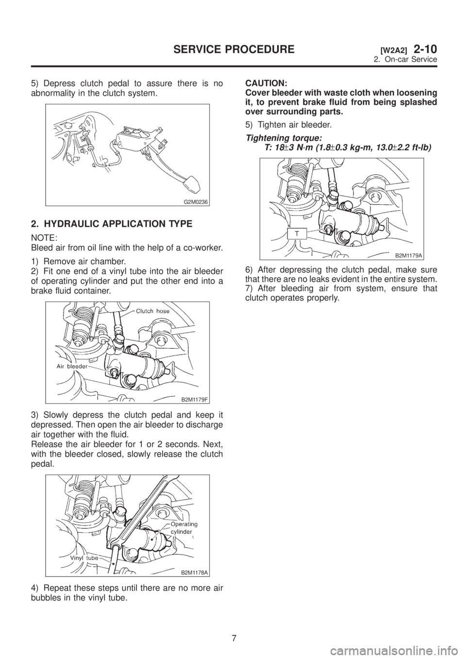
2) Fit one end of a vinyl tube into the air bleeder
of operating cylinder and put the other end into a
brake fluid container.
B2M1179F
3) Slowly depress the clutch pedal and keep it
depressed. Then open the air bleeder to discharge
air together with the fluid.
Release the air bleeder for 1 or 2 seconds. Next,
with the bleeder closed, slowly release the clutch
pedal.
B2M1178A
4) Repeat these steps until there are no more air
bubbles in the vinyl tube.CAUTION:
Cover bleeder with waste cloth when loosening
it, to prevent brake fluid from being splashed
over surrounding parts.
5) Tighten air bleeder.
Tightening torque:
T: 1 8
±3 N´m (1.8±0.3 kg-m, 13.0±2.2 ft-lb)
B2M1179A
6) After depressing the clutch pedal, make sure
that there are no leaks evident in the entire system.
7) After bleeding air from system, ensure that
clutch operates properly.
7
[W2A2]2-10SERVICE PROCEDURE
2. On-car Service