Page 358 of 2267

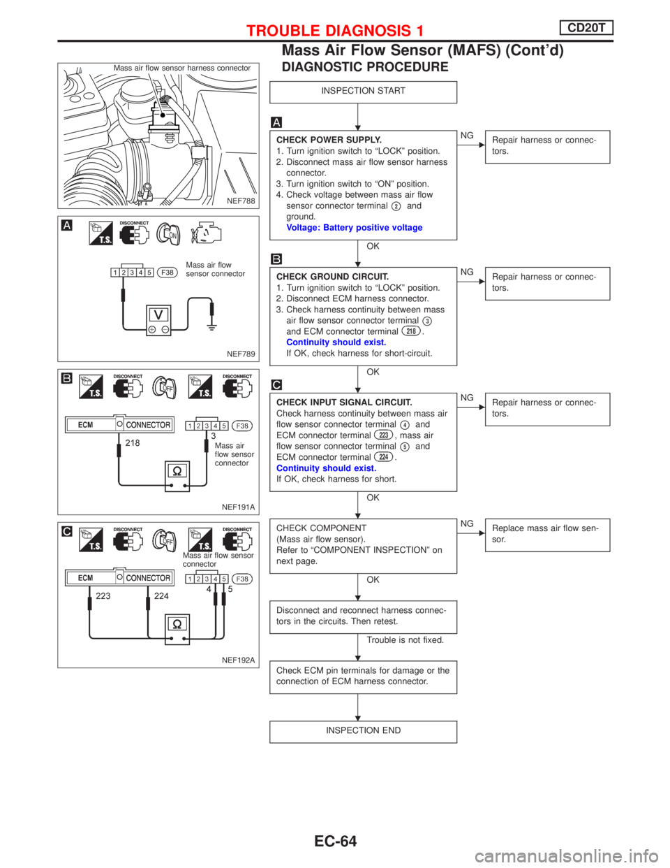
DIAGNOSTIC PROCEDURE
INSPECTION START
CHECK POWER SUPPLY.
1. Turn ignition switch to ªLOCKº position.
2. Disconnect mass air flow sensor harness
connector.
3. Turn ignition switch to ªONº position.
4. Check voltage between mass air flow
sensor connector terminal
p2and
ground.
Voltage: Battery positive voltage
OK
ENG
Repair harness or connec-
tors.
CHECK GROUND CIRCUIT.
1. Turn ignition switch to ªLOCKº position.
2. Disconnect ECM harness connector.
3. Check harness continuity between mass
air flow sensor connector terminal
p3and ECM connector terminal218.
Continuity should exist.
If OK, check harness for short-circuit.
OK
ENG
Repair harness or connec-
tors.
CHECK INPUT SIGNAL CIRCUIT.
Check harness continuity between mass air
flow sensor connector terminal
p4and
ECM connector terminal223, mass air
flow sensor connector terminal
p5and
ECM connector terminal224.
Continuity should exist.
If OK, check harness for short.
OK
ENG
Repair harness or connec-
tors.
CHECK COMPONENT
(Mass air flow sensor).
Refer to ªCOMPONENT INSPECTIONº on
next page.
OK
ENG
Replace mass air flow sen-
sor.
Disconnect and reconnect harness connec-
tors in the circuits. Then retest.
Trouble is not fixed.
Check ECM pin terminals for damage or the
connection of ECM harness connector.
INSPECTION END
NEF788 Mass air flow sensor harness connector
NEF789
Mass air flow
sensor connector
NEF191A
Mass air
flow sensor
connector
NEF192A
Mass air flow sensor
connector
H
H
H
H
H
H
H
TROUBLE DIAGNOSIS 1CD20T
Mass Air Flow Sensor (MAFS) (Cont'd)
EC-64
Page 365 of 2267
MODELS BEFORE VIN - P11U0583350
YEC801
BATTERYIGNITION SWITCH
ON or START
FUSE
BLOCK
(J/B)Refer to EL-POWER.
: Dectable line for DTC
: Non-detectable line for DTC
VEHICLE
SPEED
SENSOR COMBINATION
METER
(SPEEDOMETER)
ECM
REFER TO THE FOLLOWING
FUSE BLOCK - Junction Box (J/B)
TROUBLE DIAGNOSIS 3CD20T
Vehicle Speed Sensor (VSS) (Cont'd)
EC-71
Page 373 of 2267
YEC803
BATTERY
Refer to EL-POWER.
ENGINE
CONTROL
MODULE
RELAY: Detectable line for DTC
: Non-detectable line for DTC
INJECTION PUMP
(ELECTRIC GOVER-
NOR)
ECM
TROUBLE DIAGNOSIS 5CD20T
Electric Governor (Cont'd)
EC-79
Page 377 of 2267
YEC804
BATTERY
Refer to EL-POWER.
: Detectable line for DTC
: Non-detectable line for DTC
ENGINE
CONTROL
MODULE
RELAYINJECTION PUMP (INJEC-
TION TIMING CONTROL
VA LV E )
ECM
TROUBLE DIAGNOSIS 6CD20T
Injection Timing Control Valve (Cont'd)
EC-83
Page 378 of 2267

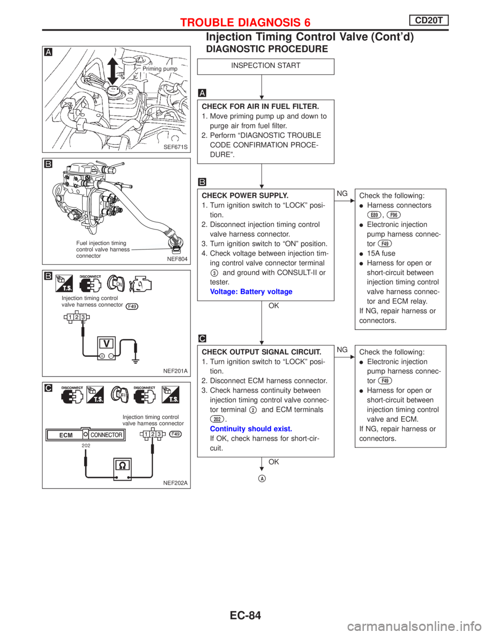
DIAGNOSTIC PROCEDURE
INSPECTION START
CHECK FOR AIR IN FUEL FILTER.
1. Move priming pump up and down to
purge air from fuel filter.
2. Perform ªDIAGNOSTIC TROUBLE
CODE CONFIRMATION PROCE-
DUREº.
CHECK POWER SUPPLY.
1. Turn ignition switch to ªLOCKº posi-
tion.
2. Disconnect injection timing control
valve harness connector.
3. Turn ignition switch to ªONº position.
4. Check voltage between injection tim-
ing control valve connector terminal
p3and ground with CONSULT-II or
tester.
Voltage: Battery voltage
OK
ENG
Check the following:
lHarness connectors
E89,F96
lElectronic injection
pump harness connec-
tor
F49
l15A fuse
lHarness for open or
short-circuit between
injection timing control
valve harness connec-
tor and ECM relay.
If NG, repair harness or
connectors.
CHECK OUTPUT SIGNAL CIRCUIT.
1. Turn ignition switch to ªLOCKº posi-
tion.
2. Disconnect ECM harness connector.
3. Check harness continuity between
injection timing control valve connec-
tor terminal
p2and ECM terminals
202.
Continuity should exist.
If OK, check harness for short-cir-
cuit.
OK
ENG
Check the following:
lElectronic injection
pump harness connec-
tor
F49
lHarness for open or
short-circuit between
injection timing control
valve and ECM.
If NG, repair harness or
connectors.
pA
SEF671S
Priming pump
NEF804
Fuel injection timing
control valve harness
connector
NEF201A
Injection timing control
valve harness connector
NEF202A
Injection timing control
valve harness connector
H
H
H
H
TROUBLE DIAGNOSIS 6CD20T
Injection Timing Control Valve (Cont'd)
EC-84
Page 383 of 2267
YEC805
BATTERYIGNITION SWITCH
ON or START
FUSE
BLOCK
(J/B)Refer to EL-POWER.
: Detectable line for DTC
: Non-detectable line for DTC
COOLING
FA N
RELAY-3COOLING
FA N
RELAY-2COOLING
FA N
RELAY-1
COOLING
FA N
MOTOR-1
LOWHIGHTRIPLE-
PRESSURE
SWITCHCOOLING
FA N
MOTOR-2
ECM
REFER TO THE FOLLOWING
FUSE BLOCK - Junction Box (J/B)
TROUBLE DIAGNOSIS 8CD20T
Cooling Fan (Overheat) (Cont'd)
EC-89
Page 385 of 2267

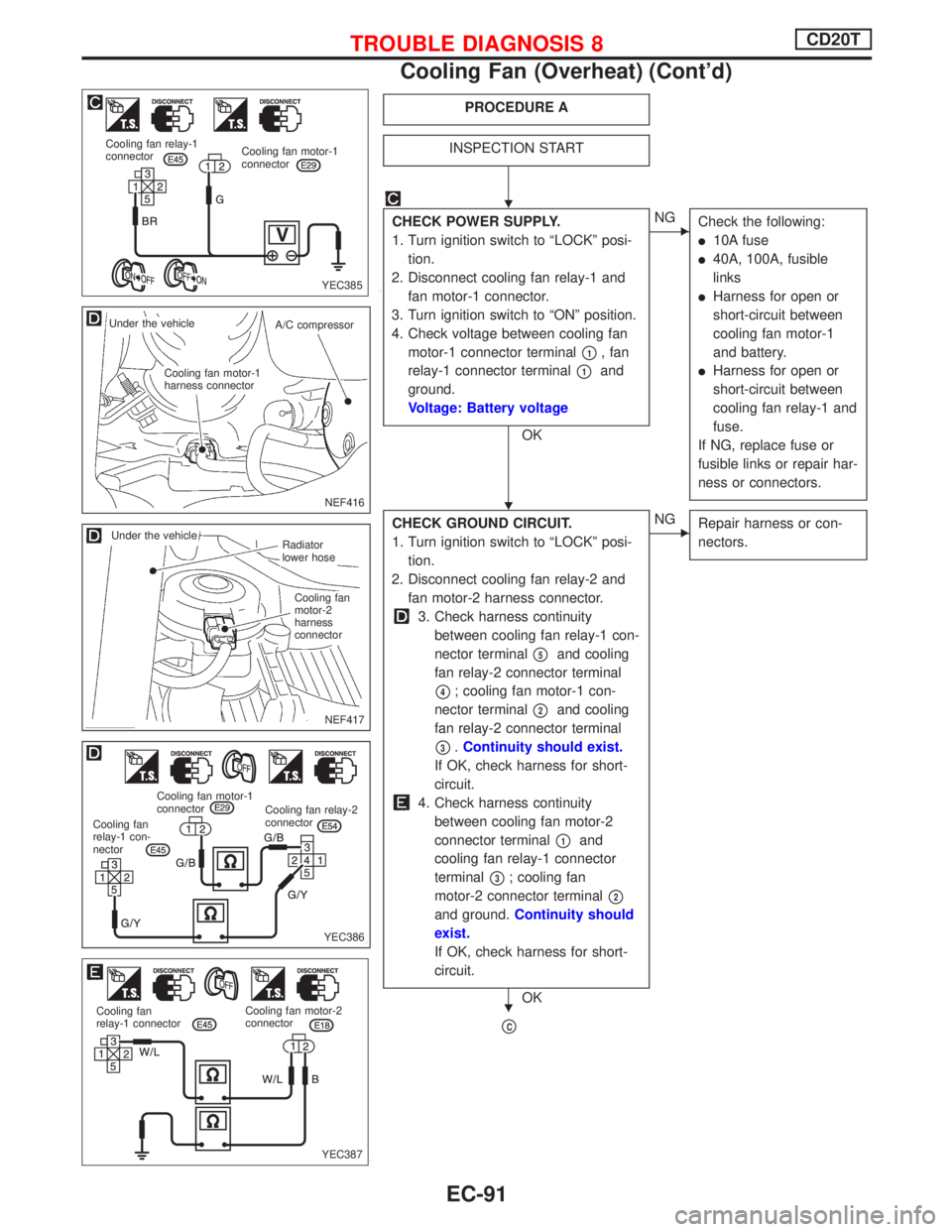
PROCEDURE A
INSPECTION START
CHECK POWER SUPPLY.
1. Turn ignition switch to ªLOCKº posi-
tion.
2. Disconnect cooling fan relay-1 and
fan motor-1 connector.
3. Turn ignition switch to ªONº position.
4. Check voltage between cooling fan
motor-1 connector terminal
p1, fan
relay-1 connector terminal
p1and
ground.
Voltage: Battery voltage
OK
ENG
Check the following:
l10A fuse
l40A, 100A, fusible
links
lHarness for open or
short-circuit between
cooling fan motor-1
and battery.
lHarness for open or
short-circuit between
cooling fan relay-1 and
fuse.
If NG, replace fuse or
fusible links or repair har-
ness or connectors.
CHECK GROUND CIRCUIT.
1. Turn ignition switch to ªLOCKº posi-
tion.
2. Disconnect cooling fan relay-2 and
fan motor-2 harness connector.
3. Check harness continuity
between cooling fan relay-1 con-
nector terminal
p5and cooling
fan relay-2 connector terminal
p4; cooling fan motor-1 con-
nector terminal
p2and cooling
fan relay-2 connector terminal
p3.Continuity should exist.
If OK, check harness for short-
circuit.
4. Check harness continuity
between cooling fan motor-2
connector terminal
p1and
cooling fan relay-1 connector
terminal
p3; cooling fan
motor-2 connector terminal
p2
and ground.Continuity should
exist.
If OK, check harness for short-
circuit.
OK
ENG
Repair harness or con-
nectors.
pC
YEC385 Cooling fan relay-1
connectorCooling fan motor-1
connector
NEF416
.Under the vehicle
A/C compressor
.Cooling fan motor-1
harness connector
NEF417
.Radiator
lower hose
.Cooling fan
motor-2
harness
connector
.Under the vehicle
YEC386
Cooling fan relay-2
connector Cooling fan motor-1
connector
Cooling fan
relay-1 con-
nector
YEC387 Cooling fan
relay-1 connectorCooling fan motor-2
connector
H
H
H
TROUBLE DIAGNOSIS 8CD20T
Cooling Fan (Overheat) (Cont'd)
EC-91
Page 386 of 2267

pC
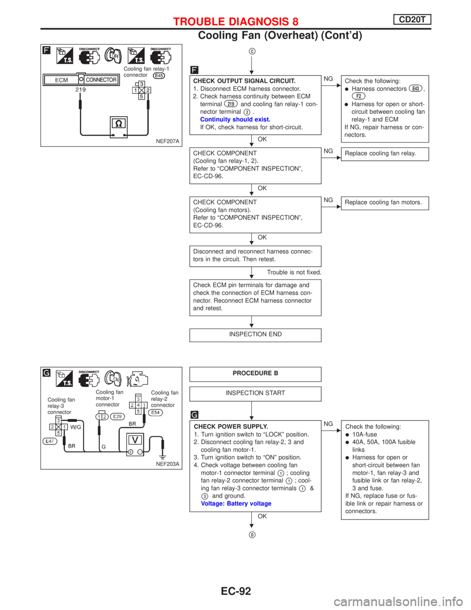
CHECK OUTPUT SIGNAL CIRCUIT.
1. Disconnect ECM harness connector.
2. Check harness continuity between ECM
terminal
219and cooling fan relay-1 con-
nector terminal
p2.
Continuity should exist.
If OK, check harness for short-circuit.
OK
ENG
Check the following:
lHarness connectorsE43,F2
lHarness for open or short-
circuit between cooling fan
relay-1 and ECM
If NG, repair harness or con-
nectors.
CHECK COMPONENT
(Cooling fan relay-1, 2).
Refer to ªCOMPONENT INSPECTIONº,
EC-CD-96.
OK
ENG
Replace cooling fan relay.
CHECK COMPONENT
(Cooling fan motors).
Refer to ªCOMPONENT INSPECTIONº,
EC-CD-96.
OK
ENG
Replace cooling fan motors.
Disconnect and reconnect harness connec-
tors in the circuit. Then retest.
Trouble is not fixed.
Check ECM pin terminals for damage and
check the connection of ECM harness con-
nector. Reconnect ECM harness connector
and retest.
INSPECTION END
PROCEDURE B
INSPECTION START
CHECK POWER SUPPLY.
1. Turn ignition switch to ªLOCKº position.
2. Disconnect cooling fan relay-2, 3 and
cooling fan motor-1.
3. Turn ignition switch to ªONº position.
4. Check voltage between cooling fan
motor-1 connector terminal
p1; cooling
fan relay-2 connector terminal
p1; cool-
ing fan relay-3 connector terminals
p1&
p3and ground.
Voltage: Battery voltage
OK
ENG
Check the following:
l10A-fusel40A, 50A, 100A fusible
links
lHarness for open or
short-circuit between fan
motor-1, fan relay-3 and
fusible link or fan relay-2,
3 and fuse.
If NG, replace fuse or fus-
ible link or repair harness or
connectors.
pD
NEF207A
Cooling fan relay-1
connector
NEF203A
Cooling fan
relay-2
connector Cooling fan
motor-1
connector Cooling fan
relay-3
connector
H
H
H
H
H
H
H
H
TROUBLE DIAGNOSIS 8CD20T
Cooling Fan (Overheat) (Cont'd)
EC-92