1999 NISSAN PRIMERA battery
[x] Cancel search: batteryPage 481 of 2267
Together with the DTC, the SRT code is cleared from the ECM memory using the method described later
(Refer to EC-QG-44). In addition, after engine control components/system are repaired or if the battery termi-
nals remain disconnected for more than 24 hours, all SRT codes may be cleared from the ECM memory.
How to Display SRT CodeNCEC0031S03011.With CONSULT-II
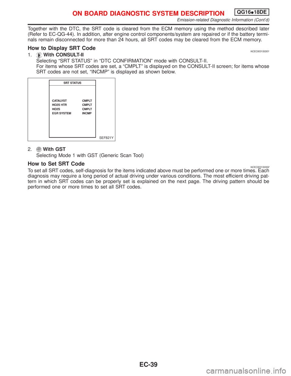
Selecting ªSRT STATUSº in ªDTC CONFIRMATIONº mode with CONSULT-II.
For items whose SRT codes are set, a ªCMPLTº is displayed on the CONSULT-II screen; for items whose
SRT codes are not set, ªINCMPº is displayed as shown below.
2.
With GST
Selecting Mode 1 with GST (Generic Scan Tool)
How to Set SRT CodeNCEC0031S0302To set all SRT codes, self-diagnosis for the items indicated above must be performed one or more times. Each
diagnosis may require a long period of actual driving under various conditions. The most efficient driving pat-
tern in which SRT codes can be properly set is explained on the next page. The driving pattern should be
performed one or more times to set all SRT codes.
SEF821Y
ON BOARD DIAGNOSTIC SYSTEM DESCRIPTIONQG16I18DE
Emission-related Diagnostic Information (Cont'd)
EC-39
Page 487 of 2267
2. Select Mode 4 with GST (Generic Scan Tool).
The emission-related diagnostic information can be erased by selecting Mode 4 with GST (Generic Scan Tool).
How to Erase DTC (No Tools)NCEC0031S06031. If the ignition switch stays ªONº after repair work, be sure to turn ignition switch ªOFFº once. Wait at least
9 seconds and then turn it ªONº again.
2. Change the diagnostic test mode from Mode II to Mode I by using the data link connector. (See EC-QG-
48.)
The emission-related diagnostic information can be erased by changing the diagnostic test mode from Diag-
nostic Test Mode II to Mode I by using the data link connector. (Refer to EC-QG-48.)
NOTE:
IIf the battery is disconnected, the emission-related diagnostic information will be lost after approx.
24 hours.
IErasing the emission-related diagnostic information using CONSULT-II or GST is easier and
quicker than switching the mode using the data link connector.
IThe following data are cleared when the ECM memory is erased.
1) Diagnostic trouble codes
2) 1st trip diagnostic trouble codes
3) Freeze frame data
4) 1st trip freeze frame data
5) System readiness test (SRT) codes
6) Test values
7) Distance traveled while MI is activated
8) Others
Actual work procedures are explained using a DTC as an example. Be careful so that not only the DTC, but
all of the data listed above, are cleared from the ECM memory during work procedures.
Malfunction Indicator (MI)
NATS (Nissan Anti-Theft System)
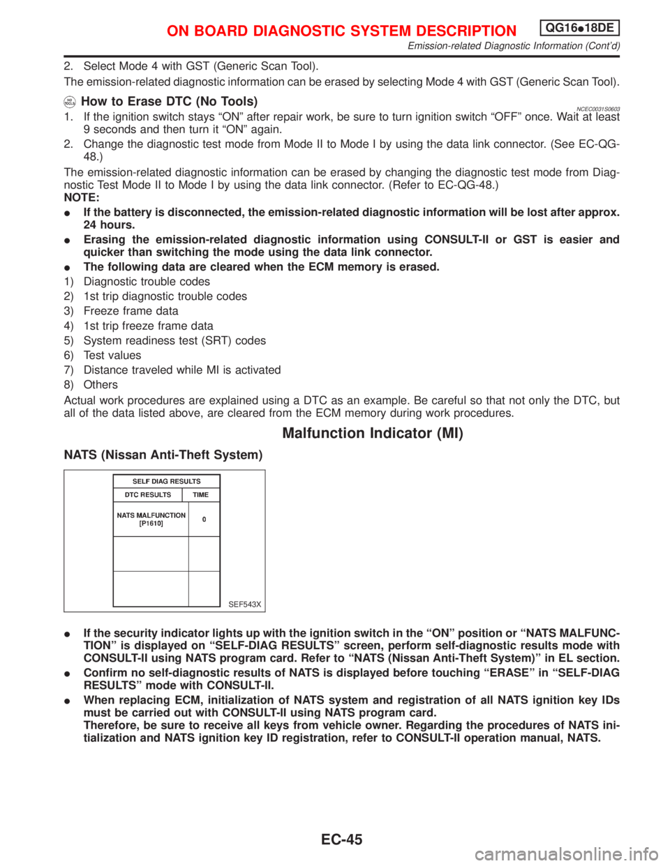
IIf the security indicator lights up with the ignition switch in the ªONº position or ªNATS MALFUNC-
TIONº is displayed on ªSELF-DIAG RESULTSº screen, perform self-diagnostic results mode with
CONSULT-II using NATS program card. Refer to ªNATS (Nissan Anti-Theft System)º in EL section.
IConfirm no self-diagnostic results of NATS is displayed before touching ªERASEº in ªSELF-DIAG
RESULTSº mode with CONSULT-II.
IWhen replacing ECM, initialization of NATS system and registration of all NATS ignition key IDs
must be carried out with CONSULT-II using NATS program card.
Therefore, be sure to receive all keys from vehicle owner. Regarding the procedures of NATS ini-
tialization and NATS ignition key ID registration, refer to CONSULT-II operation manual, NATS.
SEF543X
ON BOARD DIAGNOSTIC SYSTEM DESCRIPTIONQG16I18DE
Emission-related Diagnostic Information (Cont'd)
EC-45
Page 491 of 2267
Diagnostic Test Mode I Ð Bulb CheckNCEC0032S03In this mode, the MI on the instrument panel should stay ON. If it remains OFF, check the MI bulb. Refer to
EL section (ªWARNING LAMPSº) or see EC-QG-354.
Diagnostic Test Mode I Ð Malfunction WarningNCEC0032S04
MI Condition
ON When the malfunction is detected or the ECM's CPU is malfunctioning.
OFF No malfunction.
IThese DTC numbers are clarified in Diagnostic Test Mode II (SELF-DIAGNOSTIC RESULTS).
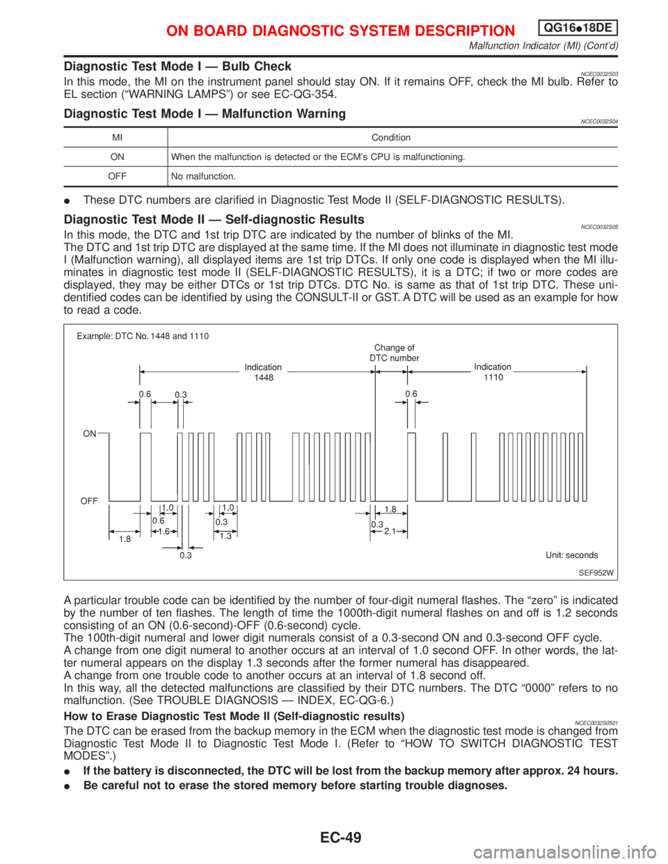
Diagnostic Test Mode II Ð Self-diagnostic ResultsNCEC0032S05In this mode, the DTC and 1st trip DTC are indicated by the number of blinks of the MI.
The DTC and 1st trip DTC are displayed at the same time. If the MI does not illuminate in diagnostic test mode
I (Malfunction warning), all displayed items are 1st trip DTCs. If only one code is displayed when the MI illu-
minates in diagnostic test mode II (SELF-DIAGNOSTIC RESULTS), it is a DTC; if two or more codes are
displayed, they may be either DTCs or 1st trip DTCs. DTC No. is same as that of 1st trip DTC. These uni-
dentified codes can be identified by using the CONSULT-II or GST. A DTC will be used as an example for how
to read a code.
A particular trouble code can be identified by the number of four-digit numeral flashes. The ªzeroº is indicated
by the number of ten flashes. The length of time the 1000th-digit numeral flashes on and off is 1.2 seconds
consisting of an ON (0.6-second)-OFF (0.6-second) cycle.
The 100th-digit numeral and lower digit numerals consist of a 0.3-second ON and 0.3-second OFF cycle.
A change from one digit numeral to another occurs at an interval of 1.0 second OFF. In other words, the lat-
ter numeral appears on the display 1.3 seconds after the former numeral has disappeared.
A change from one trouble code to another occurs at an interval of 1.8 second off.
In this way, all the detected malfunctions are classified by their DTC numbers. The DTC ª0000º refers to no
malfunction. (See TROUBLE DIAGNOSIS Ð INDEX, EC-QG-6.)
How to Erase Diagnostic Test Mode II (Self-diagnostic results)
NCEC0032S0501The DTC can be erased from the backup memory in the ECM when the diagnostic test mode is changed from
Diagnostic Test Mode II to Diagnostic Test Mode I. (Refer to ªHOW TO SWITCH DIAGNOSTIC TEST
MODESº.)
IIf the battery is disconnected, the DTC will be lost from the backup memory after approx. 24 hours.
IBe careful not to erase the stored memory before starting trouble diagnoses.
SEF952W
ON BOARD DIAGNOSTIC SYSTEM DESCRIPTIONQG16I18DE
Malfunction Indicator (MI) (Cont'd)
EC-49
Page 498 of 2267
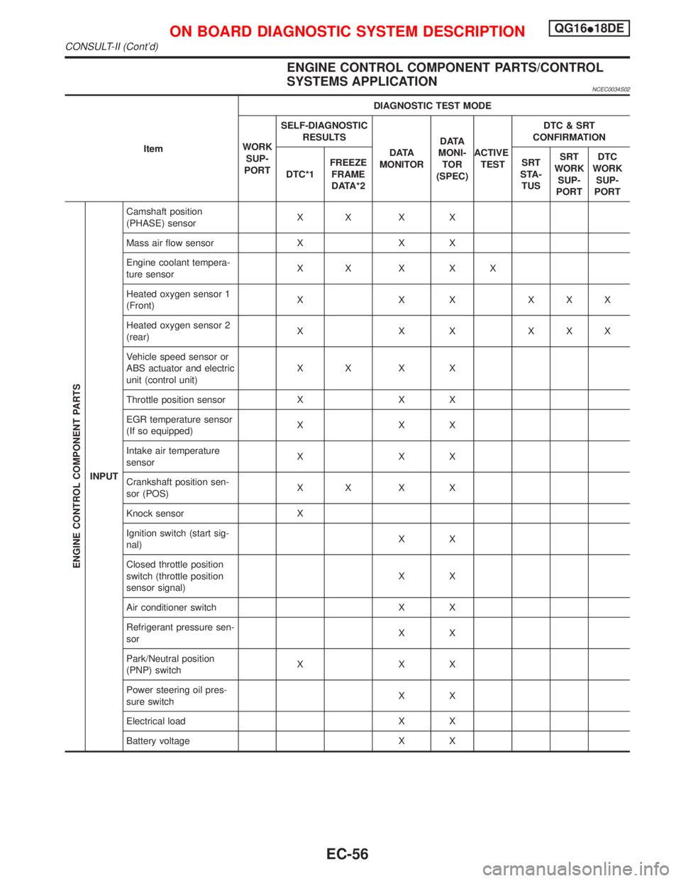
ENGINE CONTROL COMPONENT PARTS/CONTROL
SYSTEMS APPLICATION
NCEC0034S02
ItemDIAGNOSTIC TEST MODE
WORK
SUP-
PORTSELF-DIAGNOSTIC
RESULTS
D ATA
MONITORD ATA
MONI-
TOR
(SPEC)ACTIVE
TESTDTC & SRT
CONFIRMATION
DTC*1FREEZE
FRAME
DATA*2SRT
STA-
TUSSRT
WORK
SUP-
PORTDTC
WORK
SUP-
PORT
ENGINE CONTROL COMPONENT PARTS
INPUTCamshaft position
(PHASE) sensorXX X X
Mass air flow sensor X X X
Engine coolant tempera-
ture sensorXX X XX
Heated oxygen sensor 1
(Front)X X X XXX
Heated oxygen sensor 2
(rear)X X X XXX
Vehicle speed sensor or
ABS actuator and electric
unit (control unit)XX X X
Throttle position sensor X X X
EGR temperature sensor
(If so equipped)XXX
Intake air temperature
sensorXXX
Crankshaft position sen-
sor (POS)XX X X
Knock sensor X
Ignition switch (start sig-
nal)XX
Closed throttle position
switch (throttle position
sensor signal)XX
Air conditioner switch X X
Refrigerant pressure sen-
sorXX
Park/Neutral position
(PNP) switchXXX
Power steering oil pres-
sure switchXX
Electrical load X X
Battery voltage X X
ON BOARD DIAGNOSTIC SYSTEM DESCRIPTIONQG16I18DE
CONSULT-II (Cont'd)
EC-56
Page 501 of 2267
![NISSAN PRIMERA 1999 Electronic Repair Manual DATA MONITOR MODENCEC0034S06
Monitored item [Unit]ECM
input
signalsMain
signalsDescription Remarks
ENG SPEED
[rpm]qqIIndicates the engine speed computed from the
POS signal of the crankshaft position NISSAN PRIMERA 1999 Electronic Repair Manual DATA MONITOR MODENCEC0034S06
Monitored item [Unit]ECM
input
signalsMain
signalsDescription Remarks
ENG SPEED
[rpm]qqIIndicates the engine speed computed from the
POS signal of the crankshaft position](/manual-img/5/57377/w960_57377-500.png)
DATA MONITOR MODENCEC0034S06
Monitored item [Unit]ECM
input
signalsMain
signalsDescription Remarks
ENG SPEED
[rpm]qqIIndicates the engine speed computed from the
POS signal of the crankshaft position sensor.IAccuracy becomes poor if
engine speed drops below the
idle rpm.
IIf the signal is interrupted while
the engine is running, an abnor-
mal value may be indicated.
MAS A/F SE-B1 [V]qqIThe signal voltage of the mass air flow sensor is
displayed.IWhen the engine is stopped, a
certain value is indicated.
COOLAN TEMP/S
[ÉC] or [ÉF]qqIThe engine coolant temperature (determined by
the signal voltage of the engine coolant tem-
perature sensor) is displayed.IWhen the engine coolant tem-
perature sensor is open or
short-circuited, ECM enters fail-
safe mode. The engine coolant
temperature determined by the
ECM is displayed.
HO2S1 (B1) [V]qqIThe signal voltage of the heated oxygen sensor
1 (front) is displayed.
HO2S2 (B1) [V]qIThe signal voltage of the heated oxygen sensor
2 (rear) is displayed.
HO2S1 MNTR (B1)
[RICH/LEAN]qIDisplay of heated oxygen sensor 1 (front) signal
during air-fuel ratio feedback control:
RICH ... means the mixture became ªrichº, and
control is being affected toward a leaner mix-
ture.
LEAN ... means the mixture became ªleanº, and
control is being affected toward a rich mixture.IAfter turning ON the ignition
switch, ªRICHº is displayed until
air-fuel mixture ratio feedback
control begins.
IWhen the air-fuel ratio feedback
is clamped, the value just
before the clamping is dis-
played continuously.
HO2S2 MNTR (B1)
[RICH/LEAN]qIDisplay of heated oxygen sensor 2 (rear) signal:
RICH ... means the amount of oxygen after
three way catalyst is relatively small.
LEAN ... means the amount of oxygen after
three way catalyst is relatively large.IWhen the engine is stopped, a
certain value is indicated.
VHCL SPEED SE
[km/h] or [mph]qqIThe vehicle speed computed from the vehicle
speed sensor signal or ABS actuator and elec-
tric unit (control unit) signal is displayed.
BATTERY VOLT [V]qIThe power supply voltage of ECM is displayed.
THRTL POS SEN [V]qqIThe throttle position sensor signal voltage is dis-
played.
EGR TEMP SEN [V]
(If so equipped)qqIThe signal voltage of the EGR temperature sen-
sor is displayed.
INT/A TEMP SE
[ÉC] or [ÉF]qIThe intake air temperature determined by the
signal voltage of the intake air temperature sen-
sor is indicated.
START SIGNAL
[ON/OFF]qqIIndicates [ON/OFF] condition from the starter
signal.IAfter starting the engine, [OFF]
is displayed regardless of the
starter signal.
CLSD THL POS
[ON/OFF]qqIIndicates idle position [ON/OFF] computed by
ECM according to the throttle position sensor
signal.
ON BOARD DIAGNOSTIC SYSTEM DESCRIPTIONQG16I18DE
CONSULT-II (Cont'd)
EC-59
Page 524 of 2267
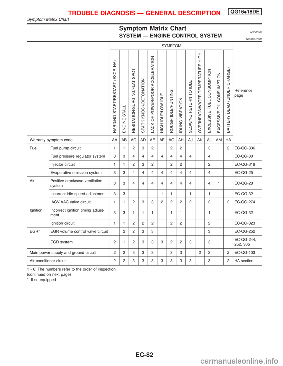
Symptom Matrix ChartNCEC0041SYSTEM Ð ENGINE CONTROL SYSTEMNCEC0041S01
SYMPTOM
Reference
page
HARD/NO START/RESTART (EXCP. HA)
ENGINE STALL
HESITATION/SURGING/FLAT SPOT
SPARK KNOCK/DETONATION
LACK OF POWER/POOR ACCELERATION
HIGH IDLE/LOW IDLE
ROUGH IDLE/HUNTING
IDLING VIBRATION
SLOW/NO RETURN TO IDLE
OVERHEATS/WATER TEMPERATURE HIGH
EXCESSIVE FUEL CONSUMPTION
EXCESSIVE OIL CONSUMPTION
BATTERY DEAD (UNDER CHARGE)
Warranty symptom code AA AB AC AD AE AF AG AH AJ AK AL AM HA
Fuel Fuel pump circuit11232 22 3 2EC-QG-336
Fuel pressure regulator system334444444 4EC-QG-30
Injector circuit11232 22 2EC-QG-319
Evaporative emission system334444444 4EC-QG-25
Air Positive crankcase ventilation
system334444444 41EC-QG-28
Incorrect idle speed adjustment 3 31111 1EC-QG-32
IACV-AAC valve circuit112332222 2 2EC-QG-274
Ignition Incorrect ignition timing adjust-
ment33111 11 1EC-QG-32
Ignition circuit11222 22 2EC-QG-323
EGR* EGR volume control valve circuit2233 3EC-QG-252
EGR system212333223 3EC-QG-244,
252, 305
Main power supply and ground circuit22333 33 23 2EC-QG-103
Air conditioner circuit223333333 3 2HAsection
1 - 6: The numbers refer to the order of inspection.
(continued on next page)
*: If so equipped
TROUBLE DIAGNOSIS Ð GENERAL DESCRIPTIONQG16I18DE
Symptom Matrix Chart
EC-82
Page 525 of 2267
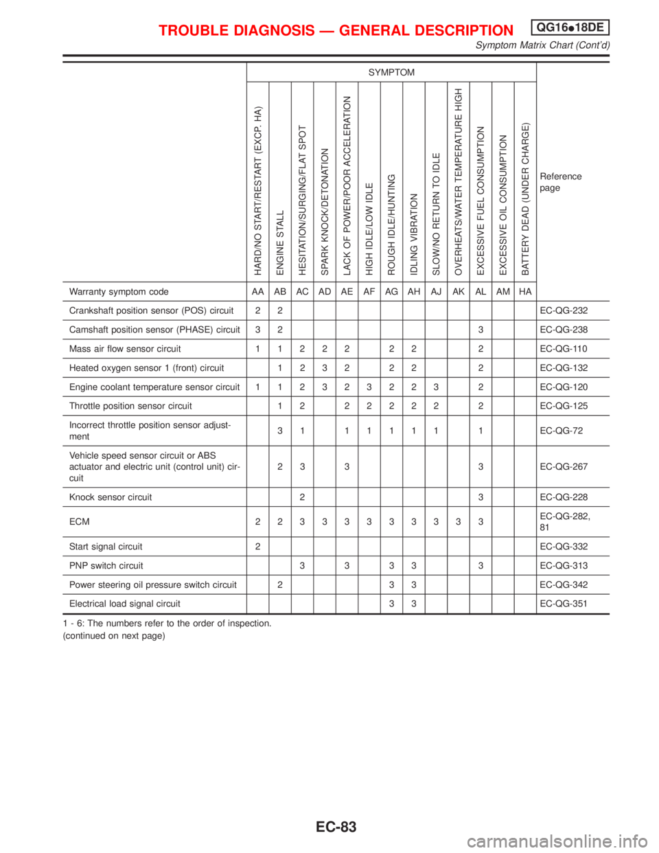
SYMPTOM
Reference
page
HARD/NO START/RESTART (EXCP. HA)
ENGINE STALL
HESITATION/SURGING/FLAT SPOT
SPARK KNOCK/DETONATION
LACK OF POWER/POOR ACCELERATION
HIGH IDLE/LOW IDLE
ROUGH IDLE/HUNTING
IDLING VIBRATION
SLOW/NO RETURN TO IDLE
OVERHEATS/WATER TEMPERATURE HIGH
EXCESSIVE FUEL CONSUMPTION
EXCESSIVE OIL CONSUMPTION
BATTERY DEAD (UNDER CHARGE)
Warranty symptom code AA AB AC AD AE AF AG AH AJ AK AL AM HA
Crankshaft position sensor (POS) circuit 2 2 EC-QG-232
Camshaft position sensor (PHASE) circuit 3 2 3 EC-QG-238
Mass air flow sensor circuit11222 22 2EC-QG-110
Heated oxygen sensor 1 (front) circuit1232 22 2EC-QG-132
Engine coolant temperature sensor circuit112323223 2EC-QG-120
Throttle position sensor circuit 1 222222 2EC-QG-125
Incorrect throttle position sensor adjust-
ment31 11111 1EC-QG-72
Vehicle speed sensor circuit or ABS
actuator and electric unit (control unit) cir-
cuit2 3 3 3 EC-QG-267
Knock sensor circuit 2 3 EC-QG-228
ECM 22333333333EC-QG-282,
81
Start signal circuit 2 EC-QG-332
PNP switch circuit 3 3 3 3 3 EC-QG-313
Power steering oil pressure switch circuit 2 3 3 EC-QG-342
Electrical load signal circuit 3 3 EC-QG-351
1 - 6: The numbers refer to the order of inspection.
(continued on next page)
TROUBLE DIAGNOSIS Ð GENERAL DESCRIPTIONQG16I18DE
Symptom Matrix Chart (Cont'd)
EC-83
Page 526 of 2267
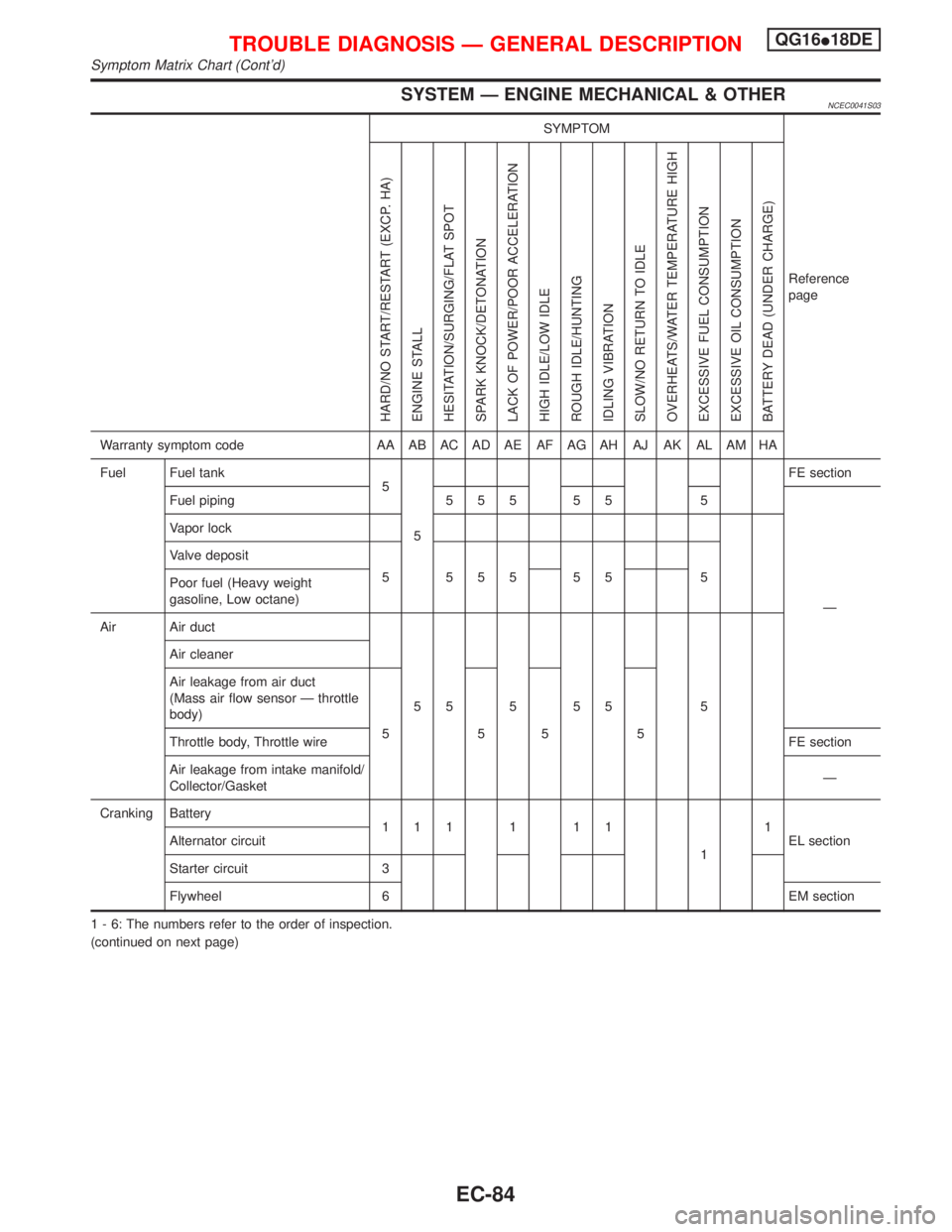
SYSTEM Ð ENGINE MECHANICAL & OTHERNCEC0041S03
SYMPTOM
Reference
page
HARD/NO START/RESTART (EXCP. HA)
ENGINE STALL
HESITATION/SURGING/FLAT SPOT
SPARK KNOCK/DETONATION
LACK OF POWER/POOR ACCELERATION
HIGH IDLE/LOW IDLE
ROUGH IDLE/HUNTING
IDLING VIBRATION
SLOW/NO RETURN TO IDLE
OVERHEATS/WATER TEMPERATURE HIGH
EXCESSIVE FUEL CONSUMPTION
EXCESSIVE OIL CONSUMPTION
BATTERY DEAD (UNDER CHARGE)
Warranty symptom code AA AB AC AD AE AF AG AH AJ AK AL AM HA
Fuel Fuel tank
5
5FE section
Fuel piping 5 5 5 5 5 5
Ð Vapor lock
Valve deposit
5 555 55 5
Poor fuel (Heavy weight
gasoline, Low octane)
Air Air duct
55555 5 Air cleaner
Air leakage from air duct
(Mass air flow sensor Ð throttle
body)
5555
Throttle body, Throttle wireFE section
Air leakage from intake manifold/
Collector/GasketÐ
Cranking Battery
111111
11
EL section Alternator circuit
Starter circuit 3
Flywheel 6 EM section
1 - 6: The numbers refer to the order of inspection.
(continued on next page)
TROUBLE DIAGNOSIS Ð GENERAL DESCRIPTIONQG16I18DE
Symptom Matrix Chart (Cont'd)
EC-84