1999 NISSAN PRIMERA clutch
[x] Cancel search: clutchPage 1851 of 2267
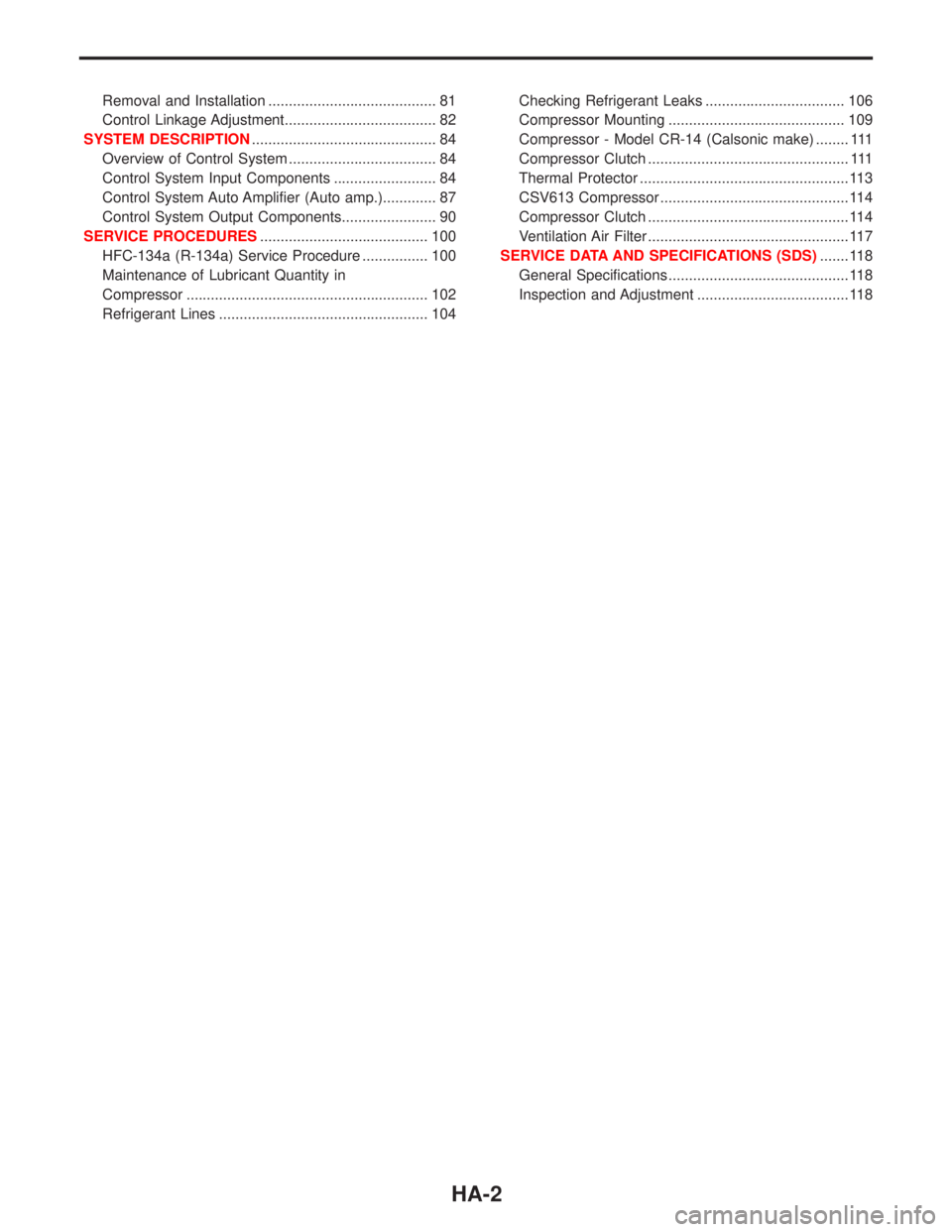
Removal and Installation ......................................... 81
Control Linkage Adjustment..................................... 82
SYSTEM DESCRIPTION............................................. 84
Overview of Control System .................................... 84
Control System Input Components ......................... 84
Control System Auto Amplifier (Auto amp.)............. 87
Control System Output Components....................... 90
SERVICE PROCEDURES......................................... 100
HFC-134a (R-134a) Service Procedure ................ 100
Maintenance of Lubricant Quantity in
Compressor ........................................................... 102
Refrigerant Lines ................................................... 104Checking Refrigerant Leaks .................................. 106
Compressor Mounting ........................................... 109
Compressor - Model CR-14 (Calsonic make) ........ 111
Compressor Clutch ................................................. 111
Thermal Protector ................................................... 113
CSV613 Compressor .............................................. 114
Compressor Clutch ................................................. 114
Ventilation Air Filter ................................................. 117
SERVICE DATA AND SPECIFICATIONS (SDS)....... 118
General Specifications ............................................ 118
Inspection and Adjustment ..................................... 118
HA-2
Page 1856 of 2267
Precautions for Servicing Compressor
lPlug all openings to prevent moisture and foreign matter from entering.
lWhen the compressor is removed, store it in the same position as it is when mounted on the car.
lWhen replacing or repairing compressor, follow ªMaintenance of Lubricant Quantity in Compres-
sorº exactly. Refer to HA-102.
lKeep friction surfaces between clutch and pulley clean. If the surface is contaminated, with
lubricant, wipe it off by using a clean waste cloth moistened with thinner.
lAfter compressor service operation, turn the compressor shaft by hand more than five turns in
both directions. This will equally distribute lubricant inside the compressor. After the compres-
sor is installed, let the engine idle and operate the compressor for one hour.
lAfter replacing the compressor magnet clutch, apply voltage to the new one and check for nor-
mal operation.
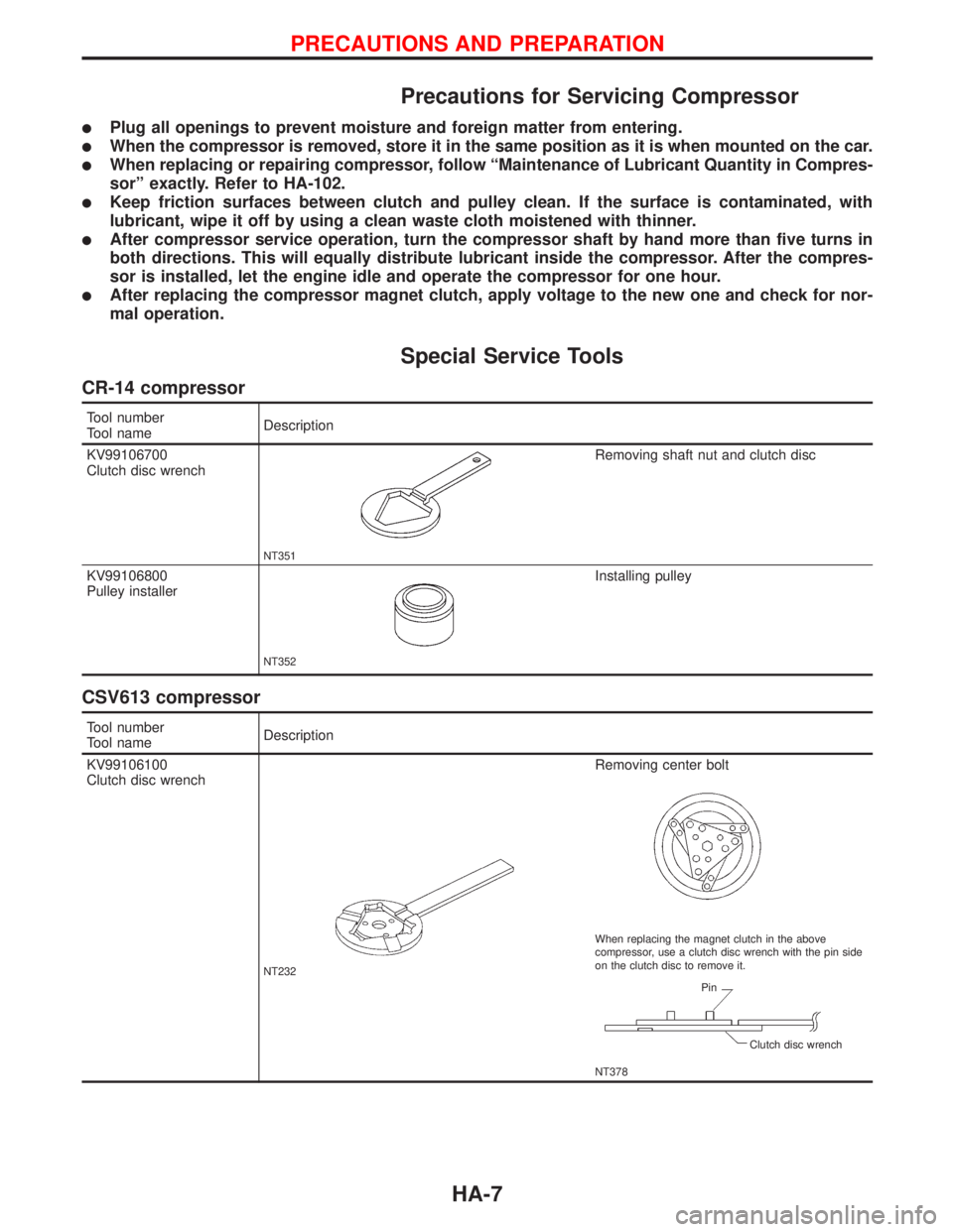
Special Service Tools
CR-14 compressor
Tool number
Tool nameDescription
KV99106700
Clutch disc wrench
NT351
Removing shaft nut and clutch disc
KV99106800
Pulley installer
NT352
Installing pulley
CSV613 compressor
Tool number
Tool nameDescription
KV99106100
Clutch disc wrench
NT232
Removing center bolt
NT378 When replacing the magnet clutch in the above
compressor, use a clutch disc wrench with the pin side
on the clutch disc to remove it.
Pin
Clutch disc wrench
PRECAUTIONS AND PREPARATION
HA-7
Page 1857 of 2267
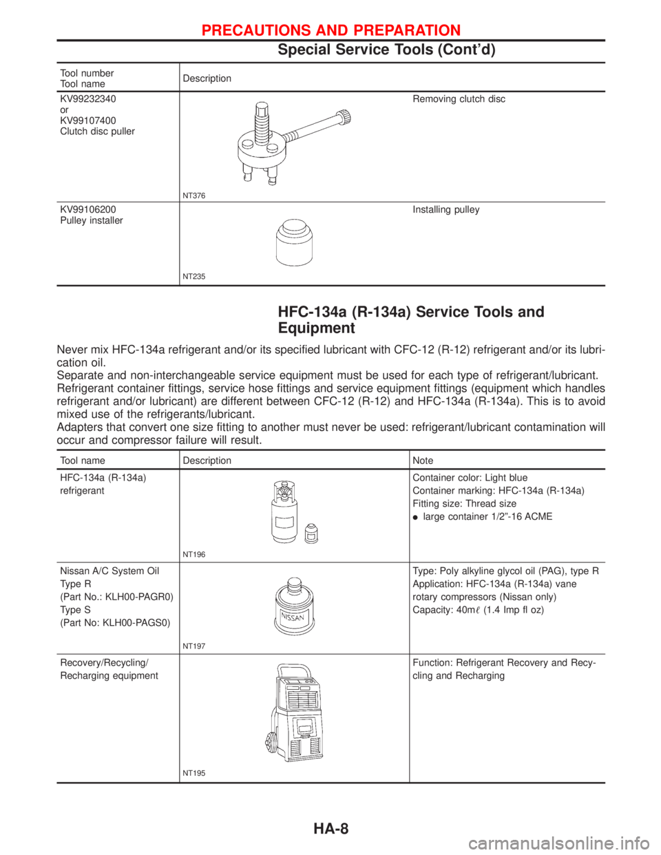
Tool number
Tool nameDescription
KV99232340
or
KV99107400
Clutch disc puller
NT376
Removing clutch disc
KV99106200
Pulley installer
NT235
Installing pulley
HFC-134a (R-134a) Service Tools and
Equipment
Never mix HFC-134a refrigerant and/or its specified lubricant with CFC-12 (R-12) refrigerant and/or its lubri-
cation oil.
Separate and non-interchangeable service equipment must be used for each type of refrigerant/lubricant.
Refrigerant container fittings, service hose fittings and service equipment fittings (equipment which handles
refrigerant and/or lubricant) are different between CFC-12 (R-12) and HFC-134a (R-134a). This is to avoid
mixed use of the refrigerants/lubricant.
Adapters that convert one size fitting to another must never be used: refrigerant/lubricant contamination will
occur and compressor failure will result.
Tool name Description Note
HFC-134a (R-134a)
refrigerant
NT196
Container color: Light blue
Container marking: HFC-134a (R-134a)
Fitting size: Thread size
llarge container 1/2º-16 ACME
Nissan A/C System Oil
Type R
(Part No.: KLH00-PAGR0)
Type S
(Part No: KLH00-PAGS0)
NT197
Type: Poly alkyline glycol oil (PAG), type R
Application: HFC-134a (R-134a) vane
rotary compressors (Nissan only)
Capacity: 40m(1.4 Imp fl oz)
Recovery/Recycling/
Recharging equipment
NT195
Function: Refrigerant Recovery and Recy-
cling and Recharging
PRECAUTIONS AND PREPARATION
Special Service Tools (Cont'd)
HA-8
Page 1863 of 2267
CSV613 Variable Displacement Compressor
GENERAL INFORMATION
1. The CSV613 compressor differs from previous units. The vent temperatures of the CSV613 compress
or do not drop too far below 5ÉC (41ÉF) when:
levaporator intake air temperature is less than 20ÉC (68ÉF)
lengine is running at speeds less than 1,500 rpm.
This is because the CSV613 compressor provides a means of ªcapacityº control.
2. The CSV613 compressor provides refrigerant control under varying conditions. During cold winters, it
may not produce high refrigerant pressure discharge (compared to previous units) when used with air
conditioning systems.
3. A ªclankingº sound may occasionally be heard during refrigerant charge. The sound indicates that the
tilt angle of the swash plate has changed and is not a problem.
4. For air conditioning systems with the CSV613 compressor, the clutch remains engaged unless: the sys-
tem main switch, fan switch or ignition switch is turned OFF. When ambient (outside) temperatures are
low or when the amount of refrigerant is insufficient, the clutch is disengaged to protect the compressor.
5. A constant range of suction pressure is maintained when engine speed is greater than a certain value.
It normally ranges from 147 to 177 kPa (1.47 to 1.77 bar, 1.5 to 1.8 kg/cm
2, 21 to 26 psi) under vary-
ing conditions.
In previous compressors, however, suction pressure was reduced with increases in engine speed.
DESCRIPTION
HA-14
Page 1869 of 2267
Introduction
The automatic temperature control (ATC) system provides automatic regulation of the discharged air tem-
perature and the discharged air volume (Blower speed).
The air outlet door, intake door and compressor magnet clutch are controlled by the manual operation of
each switch.
Features
Air mix door control (Automatic temperature control)
The air mix door is automatically controlled so that in-vehicle temperature will reach, and be maintained at
the operator selected ªset temperatureº. For a given set temperature, the air mix door position will depend
on: Ambient temperature, in-vehicle temperature, amount of sunload, set temperature and A/C switch sig-
nals.
Fan speed control
When the fan control switch is in the Auto position, the blower speed is automatically controlled, depending
on: Ambient temperature, in-vehicle temperature, amount of sunload, set temperature, and A/C switch sig-
nals. It is also controlled by the manual operation of the fan control switch.
Starting fan speed control
When engine coolant temperature is low, the air outlet door position is detected by the A/C control panel
and if this is set in B/L, FOOT or FOOT/DEF blower speed is controlled to prevent a large amount of cold
air from being discharged into the floor area.
Outlet door control
This can be selected by operation of the mode control knob.
Intake door control
This can be selected by changing the REC switch position.
Compressor magnet clutch control
System with CR-14 compressor
When the A/C switch is ON, the thermistor detects evaporator temperature. The thermo control amplifier
controls clutch ON/OFF operation depending on the evaporator temperature.
System with CSV613 compressor
Under normal operating conditions, when the A/C is switched on, the compressor runs continuously, and the
evaporator pressure, and therefore temperature, is controlled by the CSV613 variable displacement com-
pressor to prevent freeze up.
DESCRIPTIONAUTO
HA-20
Page 1877 of 2267
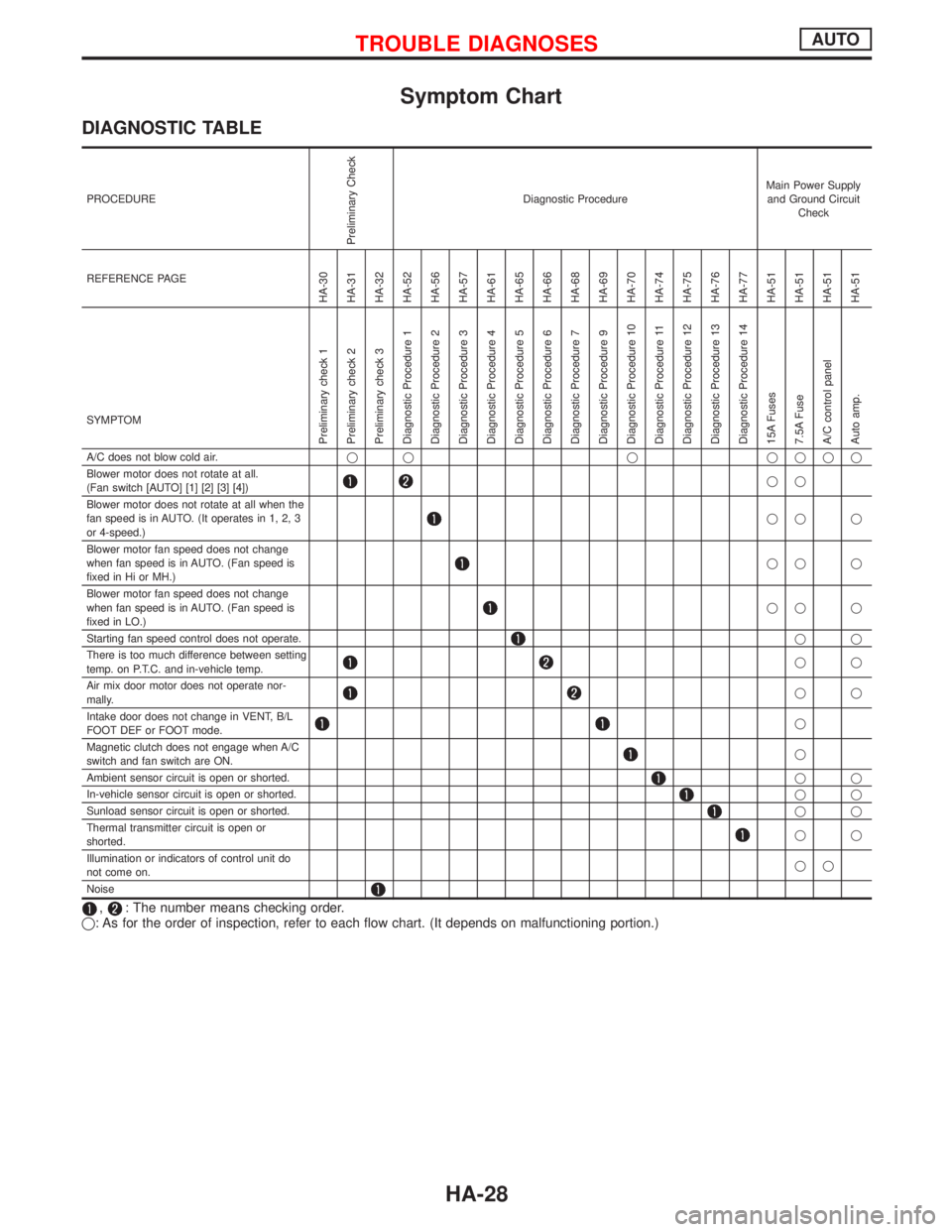
Symptom Chart
DIAGNOSTIC TABLE
PROCEDURE
Preliminary Check
Diagnostic ProcedureMain Power Supply
and Ground Circuit
Check
REFERENCE PAGE
HA-30
HA-31
HA-32
HA-52
HA-56
HA-57
HA-61
HA-65
HA-66
HA-68
HA-69
HA-70
HA-74
HA-75
HA-76
HA-77
HA-51
HA-51
HA-51
HA-51
SYMPTOM
Preliminary check 1
Preliminary check 2
Preliminary check 3
Diagnostic Procedure 1
Diagnostic Procedure 2
Diagnostic Procedure 3
Diagnostic Procedure 4
Diagnostic Procedure 5
Diagnostic Procedure 6
Diagnostic Procedure 7
Diagnostic Procedure 9
Diagnostic Procedure 10
Diagnostic Procedure 11
Diagnostic Procedure 12
Diagnostic Procedure 13
Diagnostic Procedure 14
15A Fuses
7.5A Fuse
A/C control panel
Auto amp.
A/C does not blow cold air.q q q qqqq
Blower motor does not rotate at all.
(Fan switch [AUTO] [1] [2] [3] [4])
qq
Blower motor does not rotate at all when the
fan speed is in AUTO. (It operates in 1, 2, 3
or 4-speed.)
qq q
Blower motor fan speed does not change
when fan speed is in AUTO. (Fan speed is
fixed in Hi or MH.)
qq q
Blower motor fan speed does not change
when fan speed is in AUTO. (Fan speed is
fixed in LO.)
qq q
Starting fan speed control does not operate.
qq
There is too much difference between setting
temp. on P.T.C. and in-vehicle temp.
qq
Air mix door motor does not operate nor-
mally.
qq
Intake door does not change in VENT, B/L
FOOT DEF or FOOT mode.
q
Magnetic clutch does not engage when A/C
switch and fan switch are ON.
q
Ambient sensor circuit is open or shorted.
qq
In-vehicle sensor circuit is open or shorted.
qq
Sunload sensor circuit is open or shorted.
qq
Thermal transmitter circuit is open or
shorted.
qq
Illumination or indicators of control unit do
not come on.qq
Noise
,: The number means checking order.
q: As for the order of inspection, refer to each flow chart. (It depends on malfunctioning portion.)
TROUBLE DIAGNOSESAUTO
HA-28
Page 1878 of 2267
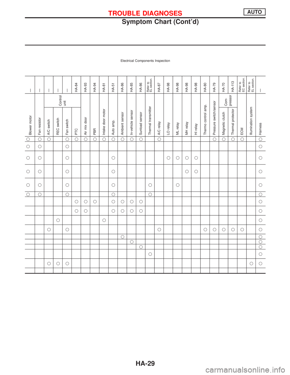
Electrical Components Inspection
Ð
Ð
Ð
Ð
Ð
HA-84
HA-93
HA-94
HA-81
HA-51
HA-86
HA-85
HA-86Refer to
EL section.HA-87
HA-98
HA-98
HA-98
HA-98
HA-80
HA-79
HA-70
HA-113Refer to
EC section.
Refer to
EL section.Ð Blower motor
Fan resistor
Control
unit
Air mix door
PBR
Intake door motor
Auto amp.
Ambient sensor
In-vehicle sensor
Sunload sensor
Thermal transmitter
A/C relay
LO relay
ML relay
MH relay
HI relay
Thermo control amp.
Pressure switch/sensor
Com-
pressor
ECM
Illumination system
Harness A/C switch
REC switch
Fan switch
PTC
Magnetic clutch
Thermal protector
q qq qqqqqqqqq q qqqq q
qq qq
q q q q qqqq q
qq q q qq q
qq q q q q q
qq q q qq
qqq qqqqq
qq qqqqq
qqq
q q q qqqqq q
qq
qq
qq
qq
qqqqq
TROUBLE DIAGNOSESAUTO
Symptom Chart (Cont'd)
HA-29
Page 1881 of 2267
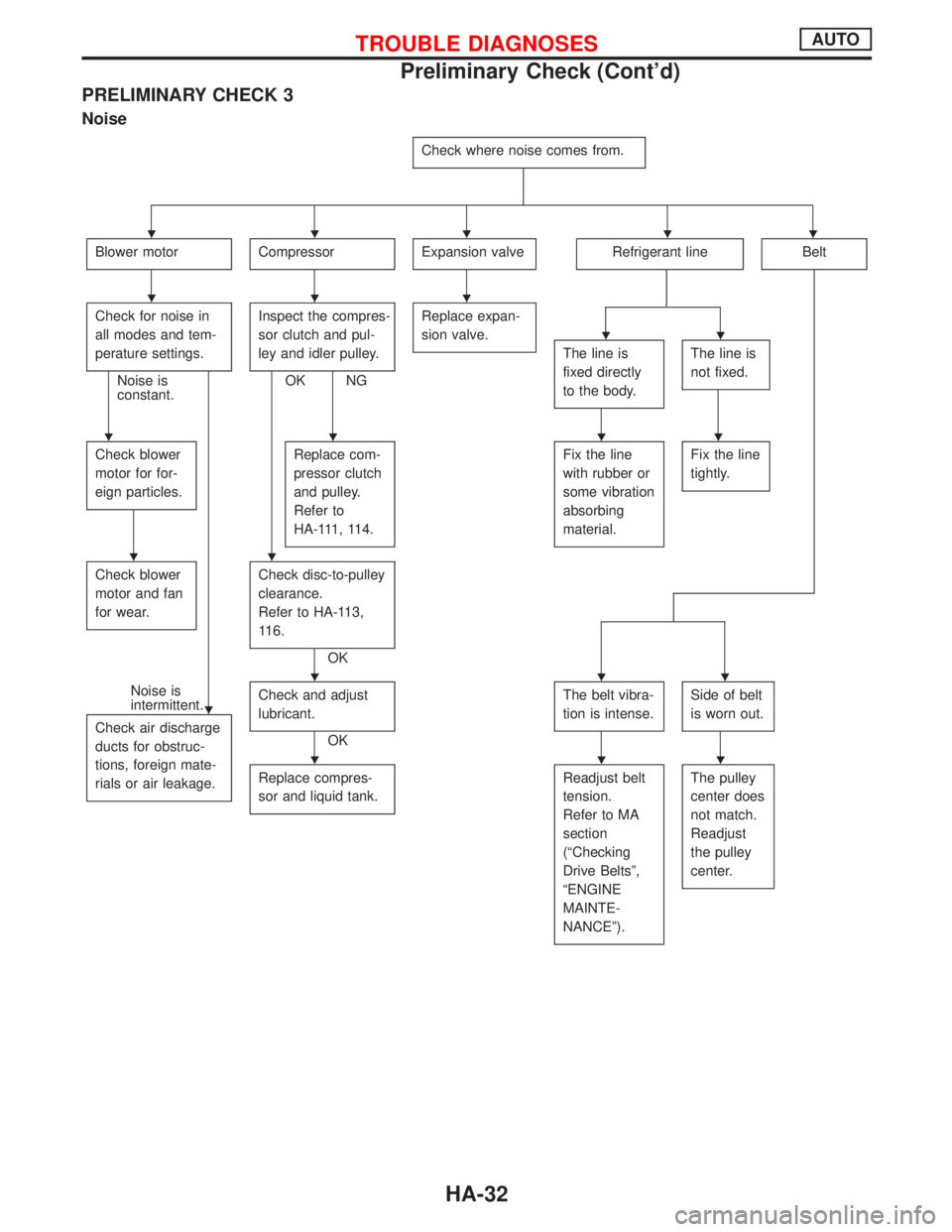
PRELIMINARY CHECK 3
Noise
Check where noise comes from.
Blower motorCompressorExpansion valveRefrigerant lineBelt
Check for noise in
all modes and tem-
perature settings.
Noise is
constant.Inspect the compres-
sor clutch and pul-
ley and idler pulley.OK NGReplace expan-
sion valve.
The line is
fixed directly
to the body.The line is
not fixed.
Check blower
motor for for-
eign particles.Replace com-
pressor clutch
and pulley.
Refer to
HA-111, 114.Fix the line
with rubber or
some vibration
absorbing
material.Fix the line
tightly.
Check blower
motor and fan
for wear.Check disc-to-pulley
clearance.
Refer to HA-113,
116.
OK
Noise is
intermittent.
Check air discharge
ducts for obstruc-
tions, foreign mate-
rials or air leakage.Check and adjust
lubricant.
OKThe belt vibra-
tion is intense.
Side of belt
is worn out.
Replace compres-
sor and liquid tank.Readjust belt
tension.
Refer to MA
section
(ªChecking
Drive Beltsº,
ªENGINE
MAINTE-
NANCEº).The pulley
center does
not match.
Readjust
the pulley
center.
HHHHH
HHH
HH
HHHH
HH
H
HHH
HHH
TROUBLE DIAGNOSESAUTO
Preliminary Check (Cont'd)
HA-32