Page 1172 of 2267

Trouble Diagnoses
If any abnormality is found, immediately disconnect battery negative terminal.
Starter does not stop.�Replace magnetic switch.
Engine does not start.
Does engine turn by cranking?
No
�Ye s
Does engine turn normally?
No (Turns slowly.)
�Ye s
Check ignition/fuel system.
Check battery as follows:�Charging condition�Terminal connections�Terminal corrosion
NG
�OK
Repair starter motor.
�A
Does starter motor turn?
No
�Ye s
Does gear shaft turn?
No
�Ye s
Check pinion clutch.
Check reduction gear, armature
and gear shaft.
Check fuse and fusible link.
OK
�NG
Replace.
Check battery as follows:�Charging condition�Terminal connections�Terminal corrosion
OK
�A
�NG�Charge battery.�Repair connections and corro-
sion of battery terminals.
Check starting system wiring.
OK
�NG
Repair.
Does magnetic switch operation
sound occur?
Ye s
�No
Replace magnetic switch
Check condition of pinion and
ring gear mesh.
NG
�OK
Does starter turn under no load
by connecting wires as follows?
SEL009Z
�Ye s
Replace magnetic switch.
�Adjust pinion movement.�Check pinion moving mecha-
nism.
�Check ring gear.
�No
Repair starter motor.
�
�
�
�
�
�
�
�
�
�
�
�
STARTING SYSTEM
EL-40
Page 1176 of 2267
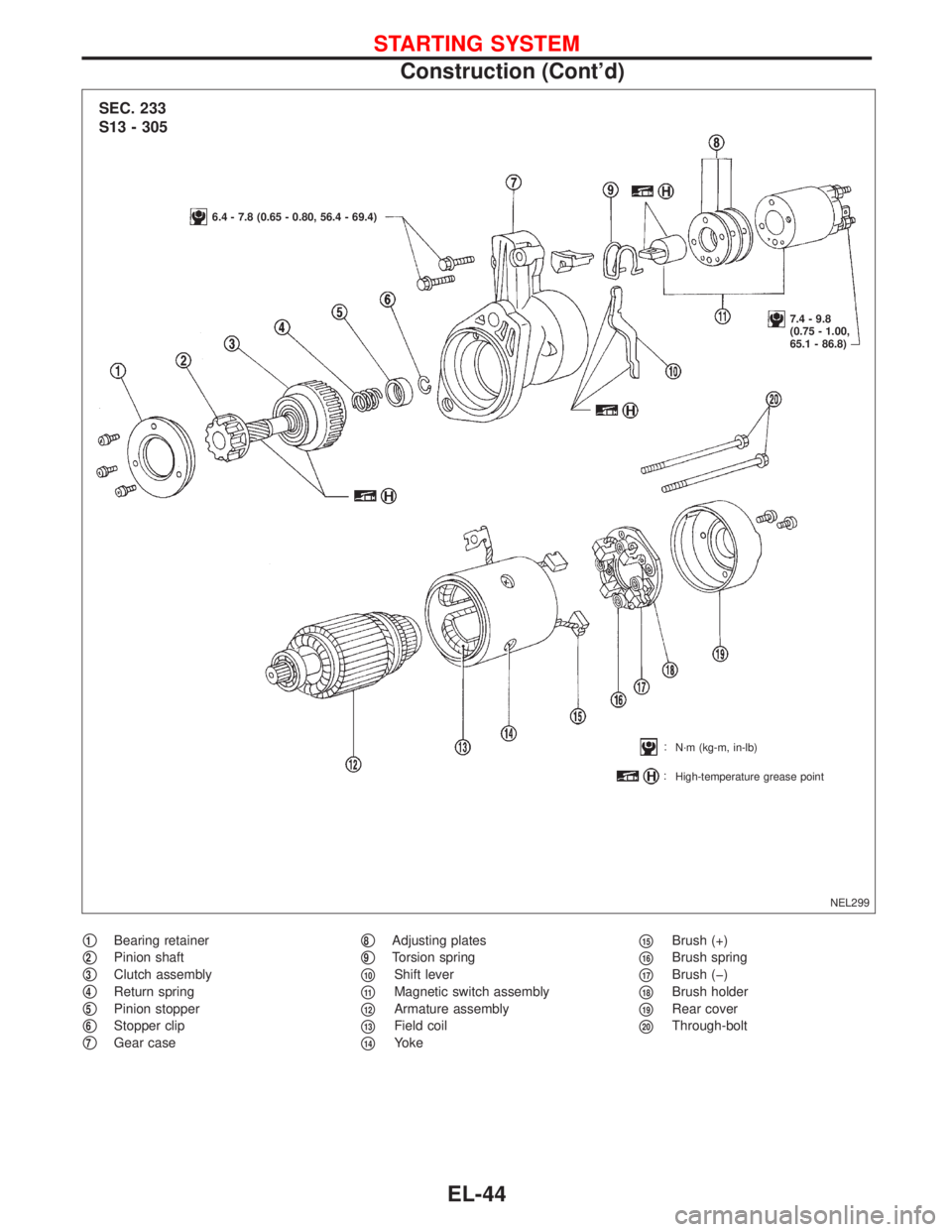
�1Bearing retainer
�2Pinion shaft
�3Clutch assembly
�4Return spring
�5Pinion stopper
�6Stopper clip
�7Gear case
�8Adjusting plates
�9Torsion spring
�10Shift lever
�11Magnetic switch assembly
�12Armature assembly
�13Field coil
�14Yoke
�15Brush (+)
�16Brush spring
�17Brush (�)
�18Brush holder
�19Rear cover
�20Through-bolt
NEL299
SEC. 233
S13 - 305
6.4 - 7.8 (0.65 - 0.80, 56.4 - 69.4)
7.4 - 9.8
(0.75 - 1.00,
65.1 - 86.8)
N·m (kg-m, in-lb)
High-temperature grease point
STARTING SYSTEM
Construction (Cont’d)
EL-44
Page 1178 of 2267
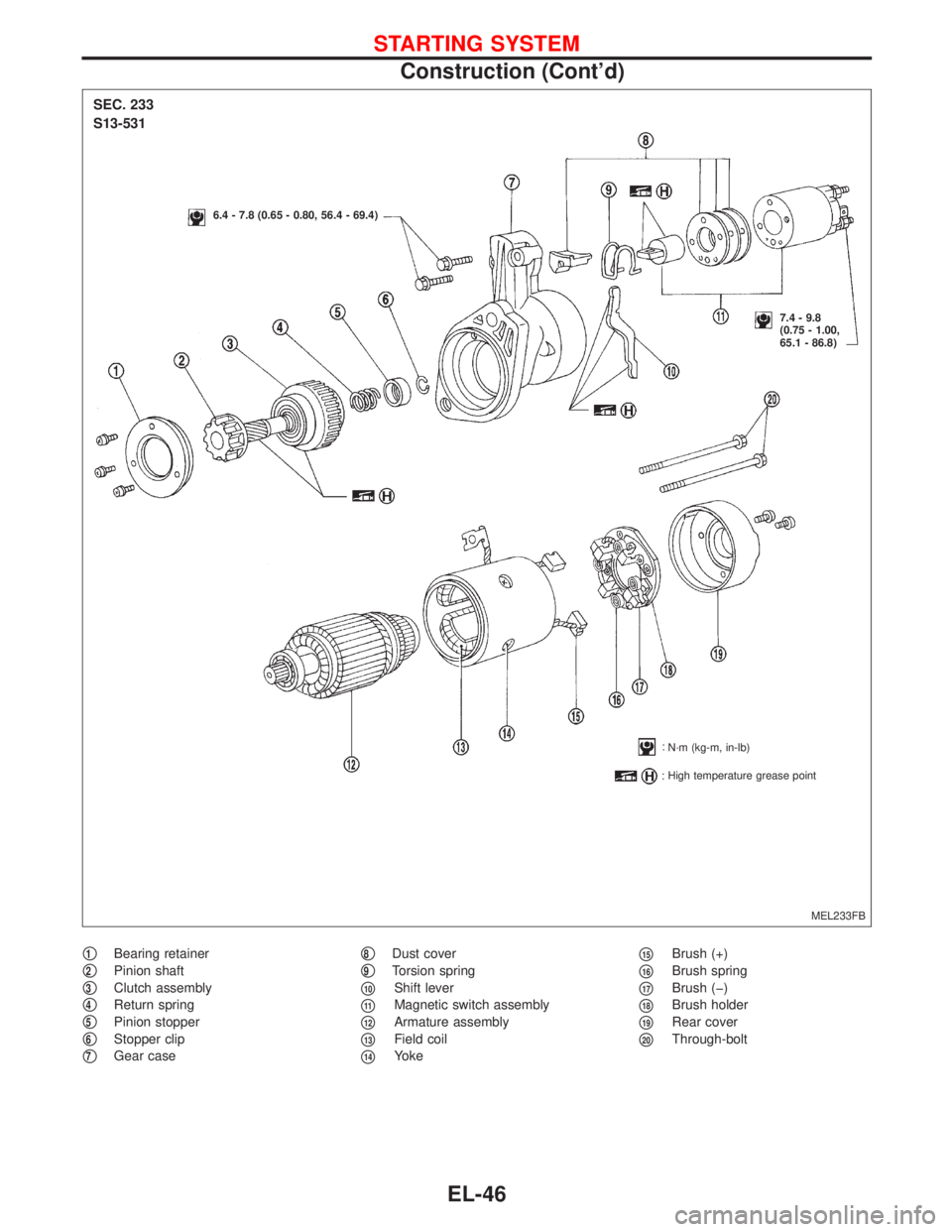
�1Bearing retainer
�2Pinion shaft
�3Clutch assembly
�4Return spring
�5Pinion stopper
�6Stopper clip
�7Gear case
�8Dust cover
�9Torsion spring
�10Shift lever
�11Magnetic switch assembly
�12Armature assembly
�13Field coil
�14Yoke
�15Brush (+)
�16Brush spring
�17Brush (�)
�18Brush holder
�19Rear cover
�20Through-bolt
MEL233FB
SEC. 233
S13-531
6.4 - 7.8 (0.65 - 0.80, 56.4 - 69.4)
7.4 - 9.8
(0.75 - 1.00,
65.1 - 86.8)
N·m (kg-m, in-lb)
High temperature grease point
STARTING SYSTEM
Construction (Cont’d)
EL-46
Page 1180 of 2267

2. Inspect reduction gear teeth.
�Replace reduction gear if teeth")
PINION/CLUTCH CHECK
1. Inspect pinion teeth.
�Replace pinion if teeth are worn or damaged. (Also check
condition of ring gear teeth.)
2. Inspect reduction gear teeth.
�Replace reduction gear if teeth are worn or damaged. (Also
check condition of armature shaft gear teeth.)
3. Check to see if pinion locks in one direction and rotates
smoothly in the opposite direction.
�If it locks or rotates in both directions, or unusual resistance
is evident. ... Replace.
BRUSH CHECK
Brush cap and lever
Check wear of brush.
Wear limit length:
Refer to SDS (EL-52).
�Excessive wear ... Replace.
Brush Spring Pressure
Check brush spring pressure with brush spring detached from
brush.
Spring pressure (with new brush):
Refer to SDS (EL-52).
�Not within the specified values ... Replace.
Brush Holder
1. Perform insulation test between brush holder (positive side)
and its base (negative side).
�Continuity exists. ... Replace.
2. Check brush to see if it moves smoothly.
�If brush holder is damaged or deformed, replace it; clear
sliding surface if dirty.
NEL303 Type 1
Type 2
SEL014Z Vernier caliper
Brush
SEL015Z Brush spring
Brush
NEL304
Type 1
STARTING SYSTEM
Inspection (Cont’d)
EL-48
Page 1703 of 2267

WARNING:
ISituate vehicle on a flat and solid surface.
IPlace chocks at front and back of rear wheels.
IDo not remove engine until exhaust system has com-
pletely cooled down.
IFor safety during subsequent steps, the tension of wires
should be slackened against the engine.
IBefore removing front axle from transaxle, place safety
stands under designated front supporting points. Refer to
GI section for lifting points and towing.
IBe sure to hoist engine and transaxle in a safe manner.
IFor engines not equipped with engine slingers, attach
proper slingers and bolts described in PARTS CATALOG
or Eurofast.
CAUTION:
IWhen lifting engine, be careful not to strike adjacent parts,
especially accelerator wire casing, brake lines, and brake
master cylinder.
IAlways use engine slingers when hoisting the engine.
IWhen removing drive shaft, be careful not to damage tran-
saxle oil seal.
1. Remove engine undercovers and splash covers.
2. Remove front exhaust tube.
3. Disconnect lower water hose from radiator and drain coolant.
4. Drain transaxle oil.
5. Remove power steering mounting bolt. (See left.)
6. Drain coolant from cylinder head.
7. Disconnect water hoses and electrical wiring from radiator and
remove radiator.
8. Disconnect fuel tubes and vacuum tubes.
9. Release power steering belt adjusting nut and remove power
steering pump from engine.
Bind pump properly to the vehicle.
10. Remove A/C compressor.
11. Disconnect or remove electrical wiring where necessary.
12. Release clutch lever cable.
13. Release tachometer cable from transaxle housing.
14. Remove front wheels.
15. Remove brake caliper mounting bolts and bind caliper properly
to vehicle LH & RH.
.SEM531D
SEM532D
ENGINE REMOVALCD20T
EM-163
Page 1815 of 2267

Use the chart below to find out what each wiring diagram code
stands for.
Code Section Wiring Diagram Name
AAC/V EC IACV-AAC Valve
ABS BR Anti-lock Brake System
ACL/S")
Wiring Diagram Codes (Cell Codes)
Use the chart below to find out what each wiring diagram code
stands for.
Code Section Wiring Diagram Name
AAC/V EC IACV-AAC Valve
ABS BR Anti-lock Brake System
ACL/SW EC Accelerator Position Switch
ADJRES EC Adjustment Resistor
A/C HA Manual Air Conditioner
A/CCUT EC Air Conditioner Cut Control
ACC/SW EC Accelerator Switch (FC)
A/T AT Automatic Transmission
AIM EL Headlamp Aiming Control
APS EC Accelerator Position Sensor
AIRREG EC IACV-Air Regulator
AT/C EC A/T Control
AUDIO EL Audio
BACK/L EL Back-up Lamp
BUZZER EL Warning Buzzer
CHARGE EL Charging System
CKPS EC Crankshaft Position Sensor
CHIME EL Warning Chime
CMPS EC Camshaft Position Sensor
COOL/F EC Cooling Fan Control
CSPS EC Control Sleeve Position Sensor
DTRL ELHeadlamp Ð With Daytime Light
System
DEF EL Rear Window Defogger
D/LOCK EL Power Door Lock
DTRL ELHeadlamp Ð With Daytime Light
System
ECTS ECEngine Coolant Temperature
Sensor
EGRC/V ECEGR and canister Control Solenoid
Valve
FCUT EC Fuel Cut Solenoid Valve
F/FOG EL Front Fog Lamp
FICD EC IACV-FICD Solenoid Valve
F/PUMP EC Fuel Pump
FTS EC Fuel Temperature Sensor
GLOW EC Quick-glow system
GOVNR EC Electric Governor
H/LAMP ELHeadlamp Ð Without Daytime
Light System
H/SEAT EL Heated Seat
HEAT HA Heater
HLC EL Headlamp Washer
HO2S EC Heated Oxygen Sensor
HORN EL Horn, Cigarette Lighter, Clock
IATS EC Intake Air Temperature Sensor
IGN/SG EC Ignition SignalCode Section Wiring Diagram Name
ILL EL Illumination
INJECT EC Injector
INT/L ELInterior, Spot and Trunk Room
Lamps
KS EC Knock Sensor
LOAD EC Load Signal
LKUP ECTorque Converter Clutch Solenoid
Valve
LOAD EC Load Signal
MAFS EC Mass Air Flow Sensor
MAIN ECMain Power Supply and Ground
Circuit
METER ELSpeedometer, Tachometer, Temp.
and Fuel Gauges
MI EC Malfunction Indicator
MIRROR EL Door Mirror
NATS EL Nissan Anti-Theft System
NLS EC Needle Lift Sensor
O2S EC Oxygen Sensor
PGC/V ECEVAP Canister Purge Control
Solenoid Valve
PLA EC Partial Load Advance Control
PNP/SW EC Park/Neutral Position Switch
POWER EL Power Supply Routing
PST/SW ECPower Steering Oil Pressure
Switch
R/FOG EL Rear Fog Lamp
SROOF EL Sun Roof
SRS RS Supplemental Restraint System
S/LOCK EL Power Door Lock Ð Super Lock
S/SIG EC Start Signal
START EL Starting System
STOP/L EL Stop Lamp
TAIL/L ELClearance, License, and Tail
Lamps
TCV EC Injection Timing Control Valve
TPS EC Throttle Position Sensor
TURN ELTurn Signal and Hazard Warning
Lamps
VSS EC Vehicle Speed Sensor
VTC EC VTC Solenoid Valve
WARN EL Warning Lamps
WINDOW EL Power Window
WIPER EL Front Wiper and Washer
WIP/R EL Rear Wiper and Washer
HOW TO READ WIRING DIAGRAMS
GI-20
Page 1846 of 2267

ISO 15031-2 Terminology List
All emission related terms used in this publication in accordance with SAE J1930 are listed. Accordingly, new
terms, new acronyms/abbreviations and old terms are listed in the following chart.
***: Not applicable
NEW TERMNEW ACRONYM /
ABBREVIATIONOLD TERM
Absolute pressure sensor *** ***
Air cleaner ACL Air cleaner
Barometric pressure BARO ***
Barometric pressure sensor-BCDD BAROS-BCDD BCDD
Camshaft position CMP ***
Camshaft position sensor CMPS Crank angle sensor
Carburetor CARB Carburetor
Charge air cooler CAC Intercooler
Closed loop CL Closed loop
Closed throttle position switch CTP switch Idle switch
Clutch pedal position switch CPP switch Clutch switch
Continuous fuel injection system CFI system ***
Continuous trap oxidizer system CTOX system ***
Crankshaft position CKP ***
Crankshaft position sensor CKPS ***
Data link connector DLC ***
Data link connector for CONSULT-II DLC for CONSULT-II Diagnostic connector for CONSULT-II
Diagnostic test mode DTM Diagnostic mode
Diagnostic test mode selector DTM selector Diagnostic mode selector
Diagnostic test mode I DTM I Mode I
Diagnostic test mode II DTM II Mode II
Diagnostic trouble code DTC Malfunction code
Direct fuel injection system DFI system ***
Distributor ignition system DI system Ignition timing control
Early fuel evaporation-mixture heater EFE-mixture heater Mixture heater
Early fuel evaporation system EFE system Mixture heater control
Electrically erasable programmable read only
memoryEEPROM ***
Electronic ignition system EI system Ignition timing control
Engine control module ECM Engine control unit
Engine coolant temperature ECT Engine temperature
Engine coolant temperature sensor ECTS Engine temperature sensor
Engine modification EM ***
Engine speed RPM Engine speed
Erasable programmable read only memory EPROM ***
Evaporative emission canister or Canister EVAP canister or Canister Canister
Evaporative emission canister purge control
solenoid valveEVAP canister purge control
solenoid valveCanister control solenoid valve
ISO 15031-2 TERMINOLOGY LIST
GI-51
Page 1849 of 2267

***: Not applicable
NEW TERMNEW ACRONYM /
ABBREVIATIONOLD TERM
Three way + oxidation catalytic converter
systemTWC + OC system ***
Throttle body TB Throttle chamber
SPI body
Throttle body fuel injection system TBI system Fuel injection control
Throttle position TP Throttle position
Throttle position sensor TPS Throttle sensor
Throttle position switch TP switch Throttle switch
Torque converter clutch solenoid valve TCC solenoid valve Lock-up cancel solenoid
Lock-up solenoid
Turbocharger TC Turbocharger
Vacuum cut valve *** Vacuum control valve
Vacuum cut valve bypass valve *** ***
Vehicle speed sensor VSS Vehicle speed sensor
Volume air flow sensor VAFS Air flow meter
Warm up oxidation catalyst WU-OC Catalyst
Warm up oxidation catalytic converter system WU-OC system ***
Warm up three way catalyst WU-TWC Catalyst
Warm up three way catalytic converter sys-
temWU-TWC system ***
Wide open throttle position switch WOTP switch Full switch
ISO 15031-2 TERMINOLOGY LIST
ISO 15031-2 Terminology List (Cont'd)
GI-54