Page 1848 of 2267

***: Not applicable
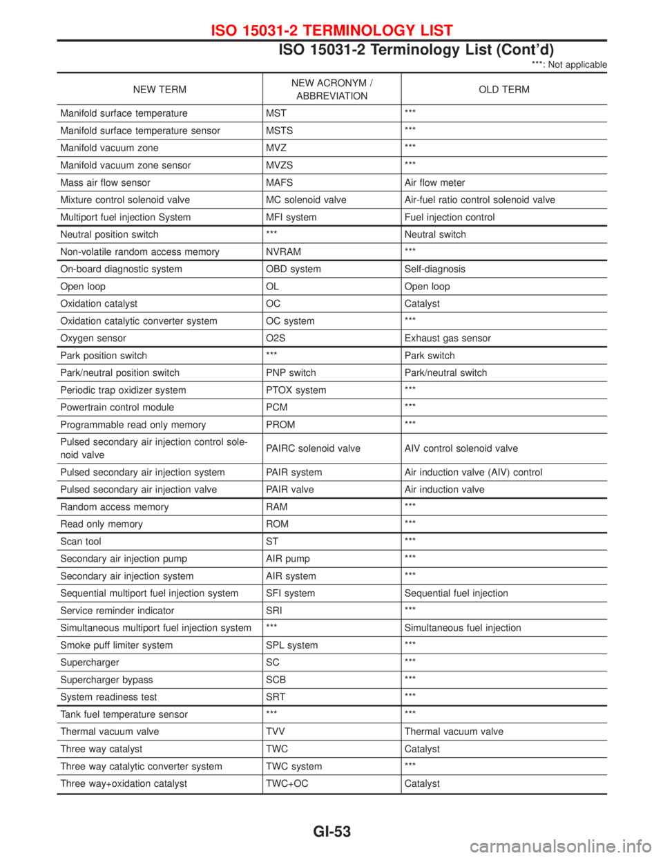
NEW TERMNEW ACRONYM /
ABBREVIATIONOLD TERM
Manifold surface temperature MST ***
Manifold surface temperature sensor MSTS ***
Manifold vacuum zone MVZ ***
Manifold vacuum zone sensor MVZS ***
Mass air flow sensor MAFS Air flow meter
Mixture control solenoid valve MC solenoid valve Air-fuel ratio control solenoid valve
Multiport fuel injection System MFI system Fuel injection control
Neutral position switch *** Neutral switch
Non-volatile random access memory NVRAM ***
On-board diagnostic system OBD system Self-diagnosis
Open loop OL Open loop
Oxidation catalyst OC Catalyst
Oxidation catalytic converter system OC system ***
Oxygen sensor O2S Exhaust gas sensor
Park position switch *** Park switch
Park/neutral position switch PNP switch Park/neutral switch
Periodic trap oxidizer system PTOX system ***
Powertrain control module PCM ***
Programmable read only memory PROM ***
Pulsed secondary air injection control sole-
noid valvePAIRC solenoid valve AIV control solenoid valve
Pulsed secondary air injection system PAIR system Air induction valve (AIV) control
Pulsed secondary air injection valve PAIR valve Air induction valve
Random access memory RAM ***
Read only memory ROM ***
Scan tool ST ***
Secondary air injection pump AIR pump ***
Secondary air injection system AIR system ***
Sequential multiport fuel injection system SFI system Sequential fuel injection
Service reminder indicator SRI ***
Simultaneous multiport fuel injection system *** Simultaneous fuel injection
Smoke puff limiter system SPL system ***
Supercharger SC ***
Supercharger bypass SCB ***
System readiness test SRT ***
Tank fuel temperature sensor *** ***
Thermal vacuum valve TVV Thermal vacuum valve
Three way catalyst TWC Catalyst
Three way catalytic converter system TWC system ***
Three way+oxidation catalyst TWC+OC Catalyst
ISO 15031-2 TERMINOLOGY LIST
ISO 15031-2 Terminology List (Cont'd)
GI-53
Page 2044 of 2267
Checking Front Heated Oxygen Sensor
(HO2S)
Checking procedure
INSPECTION START
Start engine and warm it up until water temperature indicator points to the
middle of gauge.
1. See“M/R F/C MNT”in“Data monitor”mode.
2. Run engine at about 2,000 rpm for about 2 minutes under no-
load.
3. Maintaining engine at 2,000 rpm under no-load (engine is
warmed up sufficiently.), check that the monitor fluctuates
between“LEAN”and“RICH”more than 5 times during 10 sec-
onds.
1 time RICH→LEAN→RICH
2 times RICH→LEAN→RICH→LEAN→RICH ...
OK NG
INSPECTION END
Check and adjustment should be made by
referring to IDLE SPEED/IGNITION TIMING/
IDLE MIXTURE RATIO INSPECTION (BASIC
SERVICE PROCEDURE) in EC section.
C2DMM06
NEF125A Data link connector.NEF125A Fuse box
SEF051PA Malfunction indicator lamp
�
�
��
ENGINE MAINTENANCEQG
MA-27
Page 2055 of 2267
Checking Front Heated Oxygen Sensor
(HO2S)
Checking procedure
INSPECTION START
Start engine and warm up until water temperature indicator points to the
middle of gauge.
1. See“M/R F/C MNT”in“Data monitor”mode.
2. Run engine at about 2,000 rpm for about 2 minutes under no-
load.
3. Maintaining engine at 2,000 rpm under no-load (engine is
warmed up sufficiently.), check that the monitor fluctuates
between“LEAN”and“RICH”more than 5 times during 10 sec-
onds.
1 time RICH→LEAN→RICH
2 times RICH→LEAN→RICH→LEAN→RICH ...
OK NG
INSPECTION END
Check and adjustment should be made by
referring to IDLE SPEED/IGNITION TIMING/
IDLE MIXTURE RATIO INSPECTION (BASIC
SERVICE PROCEDURE) in EC section.
PEF054P
NEF125A Data link connector.NEF125A Fuse box
SEF051PA Malfunction indicator lamp
�
�
��
ENGINE MAINTENANCESR20DE
MA-38
Page 2199 of 2267

7. Disconnect connector and remove the four screws. The spi-
ral cable can then be removed.
CAUTION:
lDo not attempt to disassemble spiral cable.
lDo not apply lubricant to the spiral cable.
Installation Ð Air Bag Module and Spiral
Cable
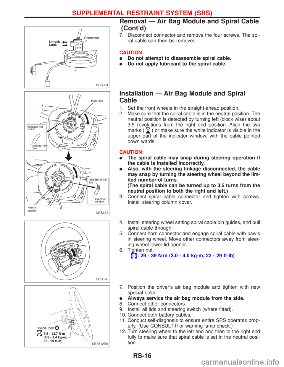
1. Set the front wheels in the straight-ahead position.
2. Make sure that the spiral cable is in the neutral position. The
neutral position is detected by turning left (clock wise) about
3.5 revolutions from the right end position. Align the two
marks (
) or make sure the white indicator is visible in the
upper part of the indicator window, with the cable pointed
down wards.
CAUTION:
lThe spiral cable may snap during steering operation if
the cable is installed incorrectly.
lAlso, with the steering linkage disconnected, the cable
may snap by turning the steering wheel beyond the lim-
ited number of turns.
(The spiral cable can be turned up to 3.5 turns from the
neutral position to both the right and left.)
3. Connect spiral cable connector and tighten with screws.
Install steering column cover.
4. Install steering wheel setting spiral cable pin guides, and pull
spiral cable through.
5. Connect horn connector and engage spiral cable with pawls
in steering wheel. Move other connectors away from steer-
ing wheel lower lid opener.
6. Tighten nut.
: 29 - 39 N´m (3.0 - 4.0 kg-m, 22 - 29 ft-lb)
7. Position the driver's air bag module and tighten with new
special bolts.
lAlways service the air bag module from the side.
8. Connect other connectors.
9. Install all lids and steering switch (where fitted).
10. Connect both battery cables.
11. Conduct self-diagnosis to ensure entire SRS operates prop-
erly. (Use CONSULT-II or warning lamp check.)
12. Turn steering wheel to the left end and then to the right end
fully to make sure that spiral cable is set in the neutral posi-
tion.
SRS384 Unlock
LockConnector
NRS121
Neutral
positionRight end
Indicator not
visible
Indicator win-
dow
Indicator is vis-
ible
Indicator
window
SRS076
SBF812EA Special bolt
7.8 - 13.7 N´m
(0.8 - 1.4 kg-m,
57 - 99 ft-lb)
SUPPLEMENTAL RESTRAINT SYSTEM (SRS)
Removal Ð Air Bag Module and Spiral Cable
(Cont'd)
RS-16