Page 89 of 122

Tire Inflation Pressure
A table (see fuel filler flap) lists the tire inflation pressures specified for Mercedes-Benz recommended tires as well as
for the varying operating conditions.
Important !
Tire pressure changes by approx. 1.5 psi (0.1 bar) per 18°F (10°C) of air temperature change. Keep this in mind
when checking tire pressure inside a garage - especially in the winter.
Example:
If garage temperature = approx. +68°F (+20°C) and ambient te mperature = approx. +32°F (0°C) then the adjusted air
pressure = specified air pressure +3 psi (+0.2 bar).
Tire pressures listed for light loads are minimum values o ffering high driving comfort. Increased inflation pressures for
heavy loads produce favorable handling characteristics with lighter loads arid are perfectly permissible. The ride of
the vehicle, however, will become somewhat harder.
Tire temperature and pressure increase with the vehicle speed. Tire pressure should therefore only be corrected on
cold tires. Correct tire pressure in warm tires only if pressure has dropped below the pressure listed in the table and
the respective operating conditions are taken into consideration.
An underinflated tire due to a slow leak (e.g. due to a
nail in the tire) may cause damage such as tread separation, bulging etc.. Regular tire pressure checks (including the
spare tire) at intervals of no more than 14 days are therefore essential. If a tire constantly loses air, it should be
inspected for damage.
Warning !
Do not overinflate tires. Overinfiating tires can result in sudden deflation (blowout) because they are more
likely to become punctured or damaged by road debris, potholes etc.. Follow recommended inflation
pressures.
Do not overload the tires by exceeding the specified vehicle capacity weight (as indicated by the label on the
driver's door latch post). Overloading the tires can overheat them, possibly causing a blowout.
ProCarManuals.com
Page 90 of 122
Exterior Lamps
Headlamp Adjustment
Correct headlamp adjustment is extremely important. Check and readjust headlamps at regular intervals and
when a bulb has been replaced.
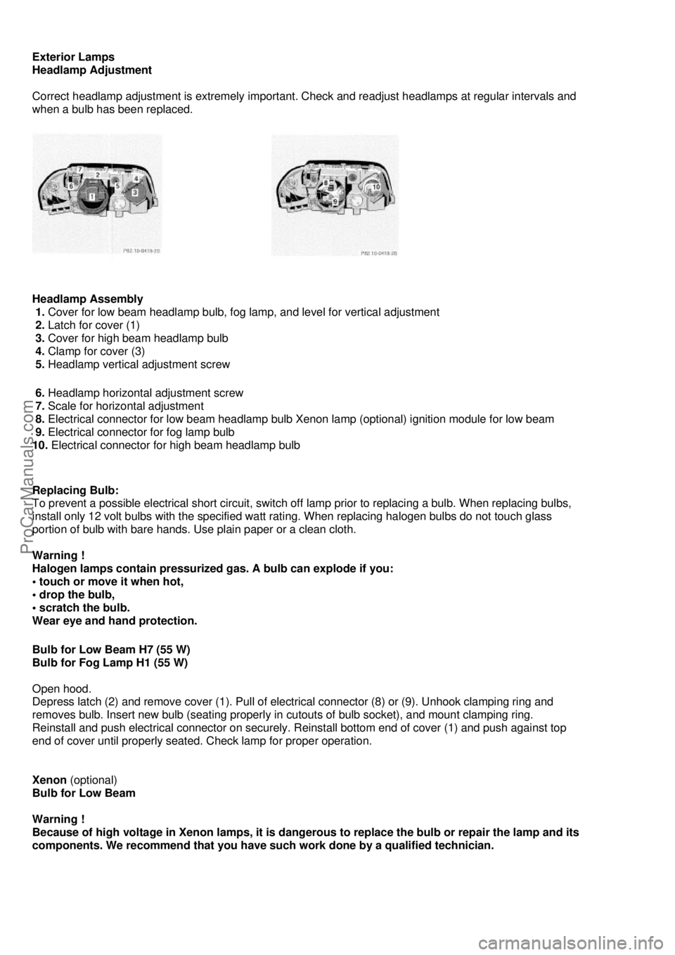
Headlamp Assembly
1. Cover for low beam headlamp bulb, fog lamp, and level for vertical adjustment
2. Latch for cover (1)
3. Cover for high beam headlamp bulb
4. Clamp for cover (3)
5. Headlamp vertical adjustment screw
6. Headlamp horizontal adjustment screw
7. Scale for horizontal adjustment
8. Electrical connector for low beam headlamp bulb Xenon lamp (optional) ignition module for low beam
9. Electrical connector for fog lamp bulb
10. Electrical connector for high beam headlamp bulb
Replacing Bulb:
To prevent a possible electrical short circuit, switch off lamp prior to replacing a bulb. When replacing bulbs,
install only 12 volt bulbs with the specified watt rati ng. When replacing halogen bulbs do not touch glass
portion of bulb with bare hands. Us e plain paper or a clean cloth.
Warning !
Halogen lamps contain pressurized gas. A bulb can explode if you:
• touch or move it when hot,
• drop the bulb,
• scratch the bulb.
Wear eye and hand protection.
Bulb for Low Beam H7 (55 W)
Bulb for Fog Lamp H1 (55 W)
Open hood.
Depress latch (2) and remove cover (1). Pull of electrical connector (8) or (9). Unhook clamping ring and
removes bulb. Insert new bulb (seating properly in cutouts of bulb socket), and mount clamping ring.
Reinstall and push electrical connector on securely. Re install bottom end of cover (1) and push against top
end of cover until properly seated. Check lamp for proper operation.
Xenon (optional)
Bulb for Low Beam
Warning !
Because of high voltage in Xenon lamps, it is dangerous to replace the bulb or repair the lamp and its
components. We recommend that you have such work done by a qualified technician.
ProCarManuals.com
Page 91 of 122
Bulb for High Beam H1 (55 W)
Open hood.
Move retaining clamps (4) aside and remove cover (3). Pull off electrical connector (10). Unhook clamping ring
and pull out bulb together with clamping ring. Remove bulb. Insert new bulb (seating properly in cutouts of bulb
socket), mount clamping ring. Reinstall and push electr ical connector on securely. Reinstall cover and fasten
with retaining clamp (4).
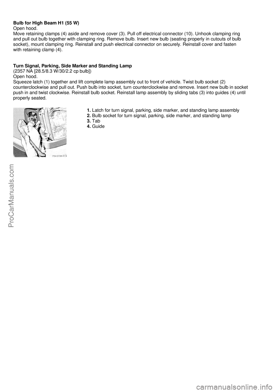
Turn Signal, Parking, Side Marker and Standing Lamp
(2357 NA [28.5/8.3 W/30/2.2 cp bulb])
Open hood.
Squeeze latch (1) together and lift complete lamp assemb ly out to front of vehicle. Twist bulb socket (2)
counterclockwise and pull out. Push bulb into socket, turn counterclockwise and remove. Insert new bulb in socket
push in and twist clockwise. Reinstall bulb socket. Reinsta ll lamp assembly by sliding tabs (3) into guides (4) until
properly seated.
1. Latch for turn signal, parking, side marker, and standing lamp assembly
2. Bulb socket for turn signal, parking, side marker, and standing lamp
3. Tab
4. Guide
ProCarManuals.com
Page 92 of 122
Adjusting Headlamp Aim
(Halogen)
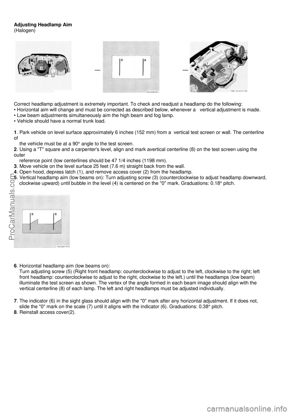
Correct headlamp adjustment is extremely important. To check and readjust a headlamp do the following:
• Horizontal aim will change and must be corrected as descri bed below, whenever a vertical adjustment is made.
• Low beam adjustments simultaneously aim the high beam and fog lamp.
• Vehicle should have a normal trunk load.
1 . Park vehicle on level surface approximately 6 inches (152 mm ) from a vertical test screen or wall. The centerline
of
the vehicle must be at a 90° angle to the test screen.
2 . Using a "T" square and a carpenter's level, align and ma rk avertical centerline (8) on the test screen using the
outer
reference point (low centerlines should be 47 1/4 inches (1198 mm).
3 . Move vehicle on the level surface 25 feet (7.6 m) straight back from the wall.
4 . Open hood, depress latch (1), and remove access cover (2) from the headlamp.
5 . Vertical headlamp aim (low beams on): Turn adjusting screw (3) (counterclockwise to adjust headlamp downward,
clockwise upward) until bubble in the level (4) is centered on the "0" mark. Graduations: 0.18° pitch.
6 . Horizontal headlamp aim (low beams on):
Turn adjusting screw (5) (Right fr ont headlamp: counterclockwise to adjust to the left, clockwise to the right; left
front headlamp: counterclockwise to adjust to the right, clockwise to the left.) until the headlamps (low beam)
illuminate the test screen as shown. The vertex of the angle formed in each beam image should align with the
vertical centerline (8) of each lamp. The left and right headlamps must be adjusted individually.
7 . The indicator (6) in the sight glass should align with the "0" mark after any horizontal adjustment. If it does not,
slide the "0" mark on the scale (7) until it a ligns with the indicator (6). Graduations: 0.38° pitch.
8 . Reinstall access cover(2).
ProCarManuals.com
Page 93 of 122
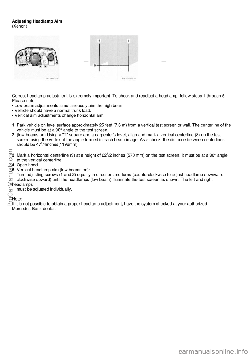
Adjusting Headlamp Aim
(Xenon)
Correct headlamp adjustment is extremely important. To ch eck and readjust a headlamp, follow steps 1 through 5.
Please note:
• Low beam adjustments simultaneously aim the high beam.
• Vehicle should have a normal trunk load.
• Vertical aim adjustments change horizontal aim.
1 . Park vehicle on level surface approximately 25 feet (7.6 m) from a vertical test screen or wall. The centerline of the
vehicle must be at a 90° angle to the test screen.
2 . (low beams on) Using a "T" square and a carpenter's leve l, align and mark a vertical centerline (8) on the test
screen using the vertex of the angle formed in each beam image. As a check, the distance between centerlines
should be 47
1/4inches(1198mm).
3 . Mark a horizontal centerline (9) at a height of 221/2 inches (570 mm) on the test screen. It must be at a 90° angle
to the vertical centerline.
4 . Open hood.
5 . Vertical headlamp aim (low beams on):
Turn adjusting screws (1 and 2) equally in direct ion and turns (counterclockwise to adjust headlamp downward,
clockwise upward) until the headlamps (low beam) illuminate the test screen as shown. The left and right
headlamps
must be adjusted individually.
Note:
If it is not possible to obtain a proper headlamp ad justment, have the system checked at your authorized
Mercedes-Benz dealer.
ProCarManuals.com
Page 94 of 122
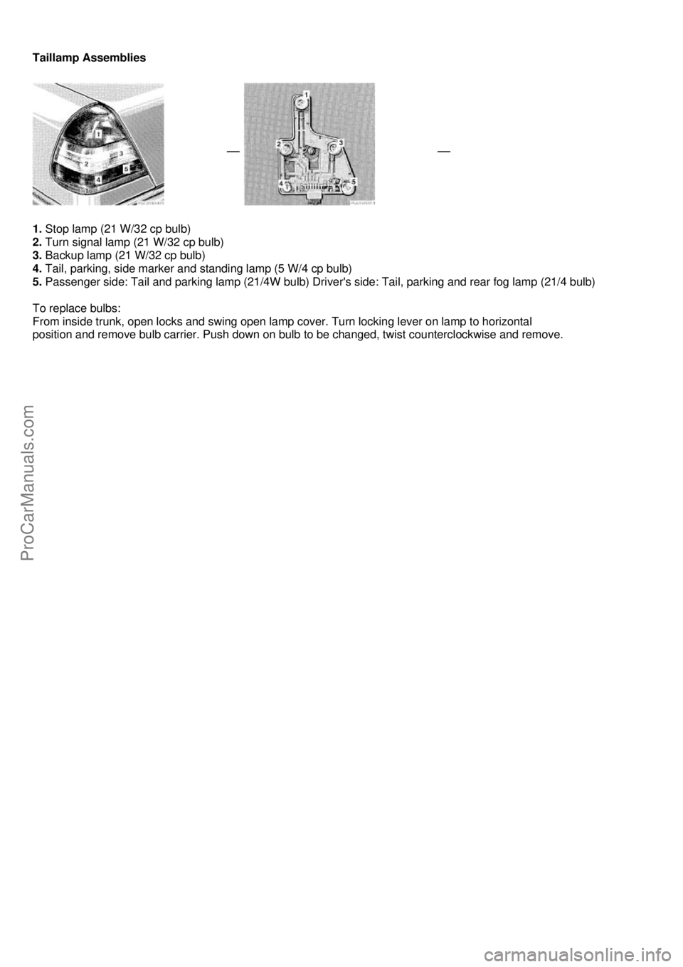
Taillamp Assemblies
1. Stop lamp (21 W/32 cp bulb)
2. Turn signal lamp (21 W/32 cp bulb)
3. Backup lamp (21 W/32 cp bulb)
4. Tail, parking, side marker and standing lamp (5 W/4 cp bulb)
5. Passenger side: Tail and parking lamp (21/4W bulb) Driver 's side: Tail, parking and rear fog lamp (21/4 bulb)
To replace bulbs:
From inside trunk, open locks and swing open lamp cover. Turn locking lever on lamp to horizontal
position and remove bulb carrier. Push down on bulb to be changed, twist counterclockwise and remove.
ProCarManuals.com
Page 95 of 122

Battery
Warning !
Failure to follow these instructions can result in severe injury or death. Never lean over batteries while
connecting, you might get injured. Battery fluid contains sulfuric acid. Do not allow this fluid to come in
contact with eyes, skin or clothing. In case it does, immediately flush affected area with water and seek
medical help if necessary. A battery will also produ ce hydrogen gas, which is flammable and explosive.
Keep flames or sparks away from battery, avoid im proper connection of jumper cables, smoking etc..
Important !
Battery maintenance information:
The battery is located in the trunk under the trunk floor. The fluid level must be checked at every A and B service.
Always insure that the fluid level is at the specified maximum level and that only distilled water is used. Failure to
maintain proper fluid level may result in cell deterioration and possible battery rupture. The service life of the battery is
dependent on its condition of charge. The battery should alwa ys be kept sufficiently charged, in order to last an
optimum length of time.
Therefore, we strongly recommend that you have the battery charge checked frequently, and corrected if
necessary, especially if you use the vehicle less than approximately 200 miles (300 km) per month, mostly for
short distance trips, or if it is not used for long periods of time.
Only charge a battery with a battery charger after the battery has been disconnected from the vehicle electrical circuit.
Always disconnect the battery negative lead first and connect last. When removing and connecting the battery,
always make sure that all electrical consumers are off and the electronic key is in steering lock position 0. The battery
and its vent tube must always be securely installed when the car is in operation. While the engine is running the
battery terminal clamps must not be loosened or detached, otherwise the generator and other electronic components
would be damaged.
Note:
After reconnecting the battery al so resynchronize the Express feature of the power windows
(see Power Windows in Index).
Battery Recycling
Batteries contain materials that can harm the environment with improper disposal. Large 12 Volt storage batteries
contain lead. Recycling of batteries is the preferred method of disposal. Many states require sellers of batteries to
accept old batteries for recycling.
ProCarManuals.com
Page 96 of 122
Fuses
1. Main fuse box in engine compartment
2. Auxiliary fuse box in trunk
3. Auxiliary fuse in trunk
4. Auxiliary fuse in engine compartment
Before replacing a blown fuse, determine the cause of the short circuit. Spare fuses are supplied inside the
main fuse box. Observe amperage and color of fuse. To gai n access to the main fuse box, release clamp (1),
lift the fuse box cover up and remove it. A special fuse puller comes with the vehicle tools. Always use a
new fuse for replacement. Never attempt to repair or bridge a blown fuse. After replacing a blown fuse, close
fuse box cover. To close the main fuse box, engag e cover at the rear and secure with clamp.
ProCarManuals.com
 1
1 2
2 3
3 4
4 5
5 6
6 7
7 8
8 9
9 10
10 11
11 12
12 13
13 14
14 15
15 16
16 17
17 18
18 19
19 20
20 21
21 22
22 23
23 24
24 25
25 26
26 27
27 28
28 29
29 30
30 31
31 32
32 33
33 34
34 35
35 36
36 37
37 38
38 39
39 40
40 41
41 42
42 43
43 44
44 45
45 46
46 47
47 48
48 49
49 50
50 51
51 52
52 53
53 54
54 55
55 56
56 57
57 58
58 59
59 60
60 61
61 62
62 63
63 64
64 65
65 66
66 67
67 68
68 69
69 70
70 71
71 72
72 73
73 74
74 75
75 76
76 77
77 78
78 79
79 80
80 81
81 82
82 83
83 84
84 85
85 86
86 87
87 88
88 89
89 90
90 91
91 92
92 93
93 94
94 95
95 96
96 97
97 98
98 99
99 100
100 101
101 102
102 103
103 104
104 105
105 106
106 107
107 108
108 109
109 110
110 111
111 112
112 113
113 114
114 115
115 116
116 117
117 118
118 119
119 120
120 121
121


