1999 DODGE NEON weight
[x] Cancel search: weightPage 931 of 1200
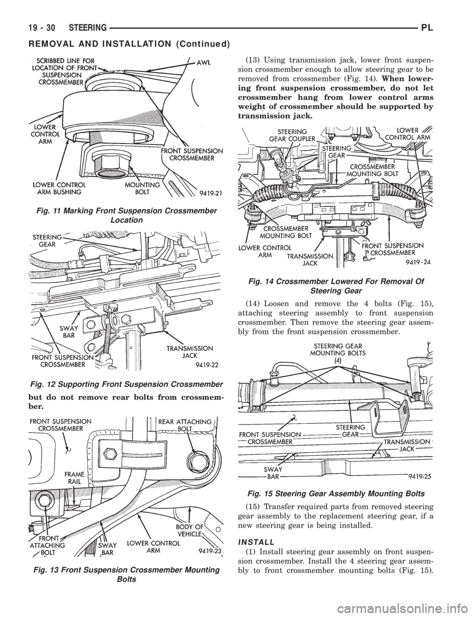
but do not remove rear bolts from crossmem-
ber.(13) Using transmission jack, lower front suspen-
sion crossmember enough to allow steering gear to be
removed from crossmember (Fig. 14).When lower-
ing front suspension crossmember, do not let
crossmember hang from lower control arms
weight of crossmember should be supported by
transmission jack.
(14) Loosen and remove the 4 bolts (Fig. 15),
attaching steering assembly to front suspension
crossmember. Then remove the steering gear assem-
bly from the front suspension crossmember.
(15) Transfer required parts from removed steering
gear assembly to the replacement steering gear, if a
new steering gear is being installed.
INSTALL
(1) Install steering gear assembly on front suspen-
sion crossmember. Install the 4 steering gear assem-
bly to front crossmember mounting bolts (Fig. 15).
Fig. 11 Marking Front Suspension Crossmember
Location
Fig. 12 Supporting Front Suspension Crossmember
Fig. 13 Front Suspension Crossmember Mounting
Bolts
Fig. 14 Crossmember Lowered For Removal Of
Steering Gear
Fig. 15 Steering Gear Assembly Mounting Bolts
19 - 30 STEERINGPL
REMOVAL AND INSTALLATION (Continued)
Page 940 of 1200
WARNING: WHEN HANDLING AN UNDEPLOYED
AIR BAG MODULE DURING SERVICING OF THE
STEERING COLUMN THE FOLLOWING PRECAU-
TIONS SHOULD BE OBSERVED. AT NO TIME
SHOULD ANY SOURCE OF ELECTRICITY BE PER-
MITTED NEAR THE INFLATOR ON THE BACK OF
THE AIR BAG MODULE. WHEN CARRYING A LIVE
MODULE, THE TRIM COVER SHOULD BE POINTED
AWAY FROM THE BODY TO MINIMIZE INJURY IF
MODULE ACCIDENTLY DEPLOYS. IF AIR BAG MOD-
ULE IS PLACED ON A BENCH OR OTHER SUR-
FACE, PLASTIC COVER SHOULD BE FACE UP TO
MINIMIZE MOVEMENT IN CASE OF ACCIDENTAL
DEPLOYMENT.
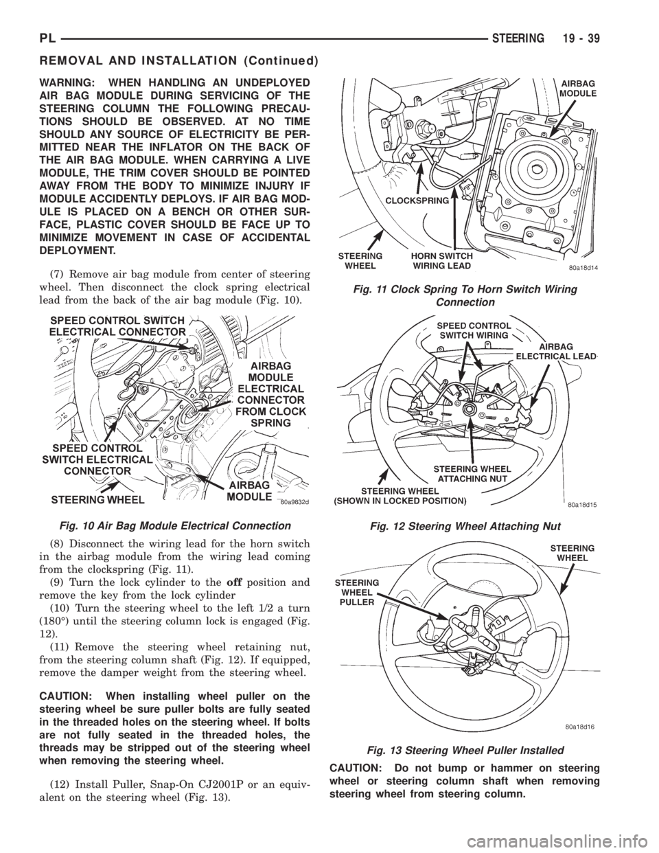
(7) Remove air bag module from center of steering
wheel. Then disconnect the clock spring electrical
lead from the back of the air bag module (Fig. 10).
(8) Disconnect the wiring lead for the horn switch
in the airbag module from the wiring lead coming
from the clockspring (Fig. 11).
(9) Turn the lock cylinder to theoffposition and
remove the key from the lock cylinder
(10) Turn the steering wheel to the left 1/2 a turn
(180É) until the steering column lock is engaged (Fig.
12).
(11) Remove the steering wheel retaining nut,
from the steering column shaft (Fig. 12). If equipped,
remove the damper weight from the steering wheel.
CAUTION: When installing wheel puller on the
steering wheel be sure puller bolts are fully seated
in the threaded holes on the steering wheel. If bolts
are not fully seated in the threaded holes, the
threads may be stripped out of the steering wheel
when removing the steering wheel.
(12) Install Puller, Snap-On CJ2001P or an equiv-
alent on the steering wheel (Fig. 13).CAUTION: Do not bump or hammer on steering
wheel or steering column shaft when removing
steering wheel from steering column.
Fig. 11 Clock Spring To Horn Switch Wiring
Connection
Fig. 12 Steering Wheel Attaching Nut
Fig. 13 Steering Wheel Puller Installed
Fig. 10 Air Bag Module Electrical Connection
PLSTEERING 19 - 39
REMOVAL AND INSTALLATION (Continued)
Page 946 of 1200
DESCRIPTION AND OPERATION
SHIFT LEVERS
The shift levers are serviceable in the vehicle. The
shift levers are different from each other and do not
interchange.
SELECTOR LEVER
The selector shaft uses a lever with a weight on
the end. The weight is used to improve shift feel and
reduce noise.
The selector lever is retained by two roll pins (one
inside the other).
AXLE SEALS
The axle shaft seals are identical for both sides of
the differential and will interchange.
DIAGNOSIS AND TESTING
COMMON PROBLEM CAUSES
The majority of transaxle malfunctions are a result
of:
²Insufficient lubrication
²Incorrect lubricant
²Misassembled or damaged internal components
²Improper operation
HARD SHIFTING
Hard shifting may be caused by a misadjusted
crossover cable. If hard shifting is accompanied by
gear clash, synchronizer clutch and stop rings, or
gear teeth may be worn or damaged.
Misassembled synchronizer components also cause
shifting problems. Incorrectly installed synchronizer
sleeves, struts, or springs can cause shift problems.
NOISY OPERATION
Transaxle noise is most often a result of worn or
damaged components. Chipped, broken gear or syn-
chronizer teeth, and brinnelled, spalled bearings all
cause noise.
Abnormal wear and damage to the internal compo-
nents is frequently the end result of insufficient
lubricant.
SLIPS OUT OF GEAR
Transaxle disengagement may be caused by mis-
aligned or damaged shift components, or worn teeth
on the drive gears or synchronizer components. Incor-
rect assembly also causes gear disengagement.
LOW LUBRICANT LEVEL
Insufficient transaxle lubricant is usually the
result of leaks, or inaccurate fluid level check or refill
method. Leakage is evident by the presence of oil
around the leak point. If leakage is not evident, the
condition is probably the result of an underfill.
If air±powered lubrication equipment is used to fill
a transaxle, be sure the equipment is properly cali-
brated. Equipment out of calibration can lead to an
underfill condition.
CLUTCH PROBLEMS
Worn, damaged, or misaligned clutch components
can cause difficult shifting, gear clash, and noise.
A worn or damaged clutch disc, pressure plate, or
release bearing can cause hard shifting and gear
clash.
SERVICE PROCEDURES
FLUID DRAIN AND FILL
All NV T350 (A-578) transaxles are equipped with
a fill plug. The fill plug is located on the left side of
the transaxle differential area (Fig. 3). The fluid level
should be within 3/16 inch from the bottom of the
transaxle fill hole (vehicle must be level when check-
ing).
All NV T350 (A-578) transaxles are equipped with
a drain plug. The drain plug is located on the lower
right side of the transaxle differential housing (Fig.
4). Tighten drain plug to 28 N´m (250 in. lbs.)
Dry fill lubricant capacity is approximately 1.9-2.2
liters (4.0-4.6 pints). Wipe the outside of the tran-
saxle if any lubricant spills.
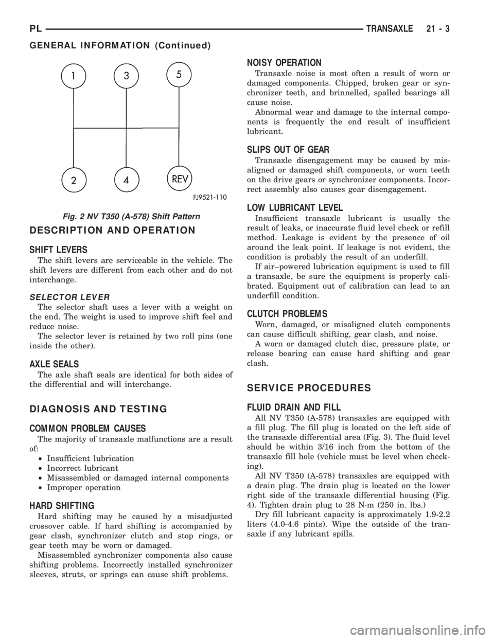
Fig. 2 NV T350 (A-578) Shift Pattern
PLTRANSAXLE 21 - 3
GENERAL INFORMATION (Continued)
Page 951 of 1200
SELECTOR LEVER
The selector shaft uses a lever with a weight on
the end. The weight is used to improve shift±feel and
reduce noise.
The selector lever is retained by two roll pins (one
inside the other).
REMOVAL
(1) Remove the selector cable. Refer to Gearshift
Cable removal.
(2) Using a pin punch, remove both roll pins from
the lever.
(3) Pull up and remove the selector lever from the
transaxle selector shaft
INSTALLATION
(1) For installation, reverse removal procedure.
Replace the roll pins that were removed with new
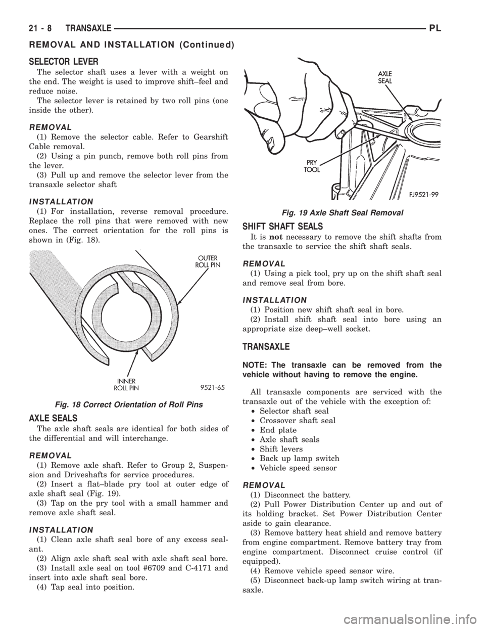
ones. The correct orientation for the roll pins is
shown in (Fig. 18).
AXLE SEALS
The axle shaft seals are identical for both sides of
the differential and will interchange.
REMOVAL
(1) Remove axle shaft. Refer to Group 2, Suspen-
sion and Driveshafts for service procedures.
(2) Insert a flat±blade pry tool at outer edge of
axle shaft seal (Fig. 19).
(3) Tap on the pry tool with a small hammer and
remove axle shaft seal.
INSTALLATION
(1) Clean axle shaft seal bore of any excess seal-
ant.
(2) Align axle shaft seal with axle shaft seal bore.
(3) Install axle seal on tool #6709 and C-4171 and
insert into axle shaft seal bore.
(4) Tap seal into position.
SHIFT SHAFT SEALS
It isnotnecessary to remove the shift shafts from
the transaxle to service the shift shaft seals.
REMOVAL
(1) Using a pick tool, pry up on the shift shaft seal
and remove seal from bore.
INSTALLATION
(1) Position new shift shaft seal in bore.
(2) Install shift shaft seal into bore using an
appropriate size deep±well socket.
TRANSAXLE
NOTE: The transaxle can be removed from the
vehicle without having to remove the engine.
All transaxle components are serviced with the
transaxle out of the vehicle with the exception of:
²Selector shaft seal
²Crossover shaft seal
²End plate
²Axle shaft seals
²Shift levers
²Back up lamp switch
²Vehicle speed sensor
REMOVAL
(1) Disconnect the battery.
(2) Pull Power Distribution Center up and out of
its holding bracket. Set Power Distribution Center
aside to gain clearance.
(3) Remove battery heat shield and remove battery
from engine compartment. Remove battery tray from
engine compartment. Disconnect cruise control (if
equipped).
(4) Remove vehicle speed sensor wire.
(5) Disconnect back-up lamp switch wiring at tran-
saxle.
Fig. 18 Correct Orientation of Roll Pins
Fig. 19 Axle Shaft Seal Removal
21 - 8 TRANSAXLEPL
REMOVAL AND INSTALLATION (Continued)
Page 1007 of 1200
VEHICLE SPEED SENSOR PINION GEAR
When the sensor is removed for any reason, a
NEW O-ring must be installed on its outside diame-
ter.
REMOVAL
(1) Remove harness connector from sensor. Be sure
weather seal stays on harness connector.
(2) Remove bolt securing the sensor in the exten-
sion housing.
(3) Carefully pull sensor and pinion gear assembly
out of extension housing.
(4) Remove pinion gear from sensor.
INSTALLATION
(1) To install, reverse the above procedure. Be sure
extension housing and sensor flange are clean prior
to installation. Always use a NEW sensor O-ring.
(2) Tighten bolt to 7 N´m (60 in. lbs.). Tighten
speedometer cable to 4 N´m (35 in. lbs.).
PARK/NEUTRAL STARTING AND BACK-UP LAMP
SWITCH
TEST
The park/neutral starting switch is the center ter-
minal of the three terminal switch. It provides
ground for the starter solenoid circuit through the
selector lever in PARK and NEUTRAL positions only.
(1) To test switch, remove wiring connector from
switch and test for continuity between center pin of
switch and transaxle case. Continuity should exist
only when transaxle is in PARK or NEUTRAL.
(2) Check gearshift cable adjustment before replac-
ing a switch that tests bad.
REMOVAL
(1) Unscrew switch from transaxle case allowing
fluid to drain into a container. Move selector lever to
PARK, then to NEUTRAL position, and inspect to see
the switch operating lever fingers are centered in
switch opening.
INSTALLATION
(1) Screw the switch with a new seal into tran-
saxle case and tighten to 33 N´m (24 ft. lbs.). Retest
switch with the test lamp.
(2) Add fluid to transaxle to bring up to proper
level.
(3) The back-up lamp switch circuit is through the
two outside terminals of the three terminal switch.
(4) To test switch, remove wiring connector from
switch and test for continuity between the two out-
side pins.
(5) Continuity should exist only with transaxle in
REVERSE position.(6) No continuity should exist from either pin to
the case.
TRANSAXLE
REMOVAL
NOTE: The transaxle can be removed from the
vehicle without having to remove the engine.
The transaxle and torque converter must be
removed as an assembly; otherwise, the torque con-
verter drive plate, pump bushing, or oil seal may be
damaged. The drive plate will not support a load;
therefore, none of the weight of the transaxle should
be allowed to rest on the plate during removal.
All transaxle components are serviced with the
transaxle out of the vehicle. The components that are
serviceable in the vehicle are:
²Axle shaft seals
²Back±up lamp switch
²End plate
²Extension housing
²Neutral safety switch
²Shift lever
²Transaxle oil pan
²Valve Body
²Vehicle speed sensor
(1) Disconnect the battery.
(2) Pull Power Distribution Center up and out of
its holding bracket. Set Power Distribution Center
aside to gain clearance.
(3) Remove battery heat shield and remove battery
from engine compartment. Remove battery tray from
engine compartment. Disconnect cruise control (if
equipped).
(4) Remove vehicle speed sensor wiring.
(5) Disconnect neutral safety switch and torque
converter control wiring at transaxle.
CAUTION: Pry up with equal force on both sides of
shifter cable isolator bushing to avoid damaging
cable isolator bushing.
(6) Disconnect gear shift cable end from transaxle
shift lever (Fig. 22). Remove bracket bolt at transaxle
(Fig. 23).
(7) Remove throttle pressure control cable from
lever. Then remove bracket bolts at the transaxle
(Fig. 24).
(8) Remove dipstick tube.
(9) Remove transaxle cooler lines and plug lines
(Fig. 25).
(10) Remove throttle pressure control cable sup-
port bracket bolts. Remove upper bellhousing bolts
and upper starter bolt (Fig. 26).
21 - 64 TRANSAXLEPL
REMOVAL AND INSTALLATION (Continued)
Page 1056 of 1200
SPECIFICATIONS
31TH AUTOMATIC TRANSAXLE
Type...........Automatic three speed with torque
converter and integral differential
Torque Converter
Diameter...............241 millimeters (9.48 in.)
Oil Capacity..............8.6 Liters (18.25 pints)
OilType..........MopartATF PLUS 3 Type 7176
Cooling Method........Water Heat Exchanger and/
or air to oil heat exchanger
Lubrication......Pump (internal-external gear-type
Gear Ratios
Transmission Portion
First Gear..............................2.69
Second Gear.............................1.55
Third Gear..............................1.00
Reverse Gear............................2.10
Pump Clearances
Outer Gear To Pocket.............0.045-0.141mm
(0.0018-0.0056 in.)
Outer Gear Side Clearance.........0.020-0.046mm
(0.0008-0.0018 in.)
Inner Gear Side Clearance.........0.020-0.046mm
(0.0008-0.0018 in.)
Tapered Roller Bearing Settings
Differential Assembly . . .6 to 12 in. lbs. Drag Torque
Output Hub............0to3in.lbs. Drag Torque
Transfer Shaft.........0.002 to 0.010 in. End Play
Overall Drag At Output Hub . . .3 to 16 in. lbs. Drag
Torque
Clutch Pack Clearances
Front Clutch (Not Adjustable)........1.27-2.79mm
(0.050-0.110 in.)
Rear Clutch.........0.71-1.10mm (0.028-0.043 in.)
Band Adjustment
Kickdown, Backed Off From
8N²m (72 in. lbs.)...............21/4Turns
Low-Reverse, Backed Off From
5N²m (41 in. lbs.)................31/2Turns
31TH TRANSAXLE TORQUE SPECIFICATIONS
DESCRIPTION TORQUE
Bell Housing Cover Bolts......12N´m(105 in. lbs.)
Cooler Hose To Rad. Conn......12N´m(105 in. lbs.)
Cooler Line Conn............28N´m(250 in. lbs.)
Diff. Bear. Ret. To Case Bolt . . .34 N´m (300 in. lbs.)
Diff. Cover To Case Bolt.......19N´m(165 in. lbs.)
Exten. Hous. To Case Bolt.....28N´m(250 in. lbs.)Flex Plate To Crankshaft Bolts . . .95 N´m (70 ft. lbs.)
Flex Plate To Torque
Conv. Bolts................68N´m(50ft.lbs.)
Fluid Filter Screw.............5N´m(45in.lbs.)
Front Motor Mount Bolt........54N´m(40ft.lbs.)
Governor Counterweight
Screw...................28N´m(250 in. lbs.)
Governor To Support Bolt.......7N´m(60in.lbs.)
Kickdown Band Adj. Lock Nut . . .47 N´m (35 ft. lbs.)
Left Motor Mount Bolts........54N´m(40ft.lbs.)
Lower Bell Housing
Cover Screw...............41N´m(30ft.lbs.)
Manual Cable To Trans.
Case Bolt................28N´m(250 in. lbs.)
Manual Control Lever Screw . . .12 N´m (105 in. lbs.)
Oil Pan To Trans. Case Screw . .19 N´m (165 in. lbs.)
Output Gear Strap Bolts........23N´m(17ft.lbs.)
Output Shaft Nut...........271 N´m (200 ft. lbs.)
Park/Neutral Switch...........34N´m(25ft.lbs.)
Pressure Check Plug...........5N´m(45in.lbs.)
Pump To Case Bolts..........31N´m(275 in. lbs.)
Reaction Shaft Assembly Bolt . .28 N´m (250 in. lbs.)
Rear Cover To Case Screw.....19N´m(165 in. lbs.)
Reverse Band Adj. Lock Nut . . .14 N´m (125 in. lbs.)
Reverse Band Shaft Plug........7N´m(60in.lbs.)
Ring Gear Screw..............95N´m(70ft.lbs.)
Speedo. To Ext. Hous. Screw.....7N´m(60in.lbs.)
Sprag Ret. To Transfer
Case Bolt................28N´m(250 in. lbs.)
Starter To Trans. Bell Bolts.....54N´m(40ft.lbs.)
Stirrup Strap Ret. Bolts.......23N´m(200 in. lbs.)
Throttle Cable To Trans.
Case Bolt................12N´m(105 in. lbs.)
Throttle Lever To Trans.
Shaft Bolts...............12N´m(105 in. lbs.)
Trans. To Cyl. Block Bolt.......95N´m(70ft.lbs.)
Transfer Shaft Nut..........271 N´m (200 ft. lbs.)
Transfer Gear Strap Bolts......23N´m(17ft.lbs.)
Valve Body Assy. To
Case Bolts...............12N´m(105 in. lbs.)
Valve Body Screw..............5N´m(45in.lbs.)
PLTRANSAXLE 21 - 113
Page 1075 of 1200
WHEELS
INDEX
page page
DESCRIPTION AND OPERATION
WHEEL COVER (LOCK-ON)................. 8
WHEEL INFORMATION.................... 8
DIAGNOSIS AND TESTING
TIRE AND WHEEL RUNOUT................ 9
WHEEL INSPECTION...................... 9
SERVICE PROCEDURES
TIRE AND WHEEL BALANCE............... 10REMOVAL AND INSTALLATION
WHEEL AND TIRE....................... 12
WHEEL COVER (LOCK-ON)................ 12
WHEEL COVER RETAINING NUT........... 13
SPECIFICATIONS
WHEEL SPECIFICATIONS................. 14
DESCRIPTION AND OPERATION
WHEEL INFORMATION
Original equipment wheels are designed for proper
operation at all loads up to the specified maximum
vehicle capacity.
All models use steel or cast aluminum drop center
wheels. Every wheel has raised sections between the
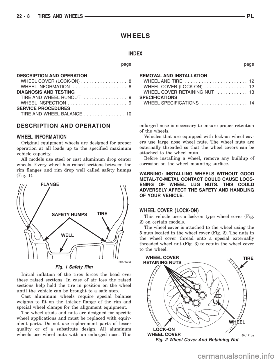
rim flanges and rim drop well called safety humps
(Fig. 1).
Initial inflation of the tires forces the bead over
these raised sections. In case of air loss the raised
sections help hold the tire in position on the wheel
until the vehicle can be brought to a safe stop.
Cast aluminum wheels require special balance
weights to fit on the thicker flange of the rim and
special wheel clamps for the alignment equipment.
The wheel studs and nuts are designed for specific
wheel applications and must be replaced with equiv-
alent parts. Do not use replacement parts of lesser
quality or of a substitute design. All aluminum
wheels use wheel nuts with an enlarged nose. Thisenlarged nose is necessary to ensure proper retention
of the wheels.
Vehicles that are equipped with lock-on wheel cov-
ers use large nose wheel nuts. The wheel nuts are
externally threaded so that the wheel covers can be
attached to the wheel nuts.
Before installing a wheel, remove any buildup of
corrosion on the wheel mounting surface.
WARNING: INSTALLING WHEELS WITHOUT GOOD
METAL-TO-METAL CONTACT COULD CAUSE LOOS-
ENING OF WHEEL LUG NUTS. THIS COULD
ADVERSELY AFFECT THE SAFETY AND HANDLING
OF YOUR VEHICLE.
WHEEL COVER (LOCK-ON)
This vehicle uses a lock-on type wheel cover (Fig.
2) on certain models.
The wheel cover is attached to the wheel using the
5 nuts located in the wheel cover (Fig. 2). The nuts in
the wheel cover thread onto a special externally
threaded wheel nut (Fig. 3) to retain the wheel cover
to the wheel.
Fig. 1 Safety Rim
Fig. 2 Wheel Cover And Retaining Nut
22 - 8 TIRES AND WHEELSPL
Page 1077 of 1200
Relocate the wheel on the mounting studs, two
studs over from the original position.
Retighten wheel nuts until all are properly
torqued. This will prevent brake distortion.
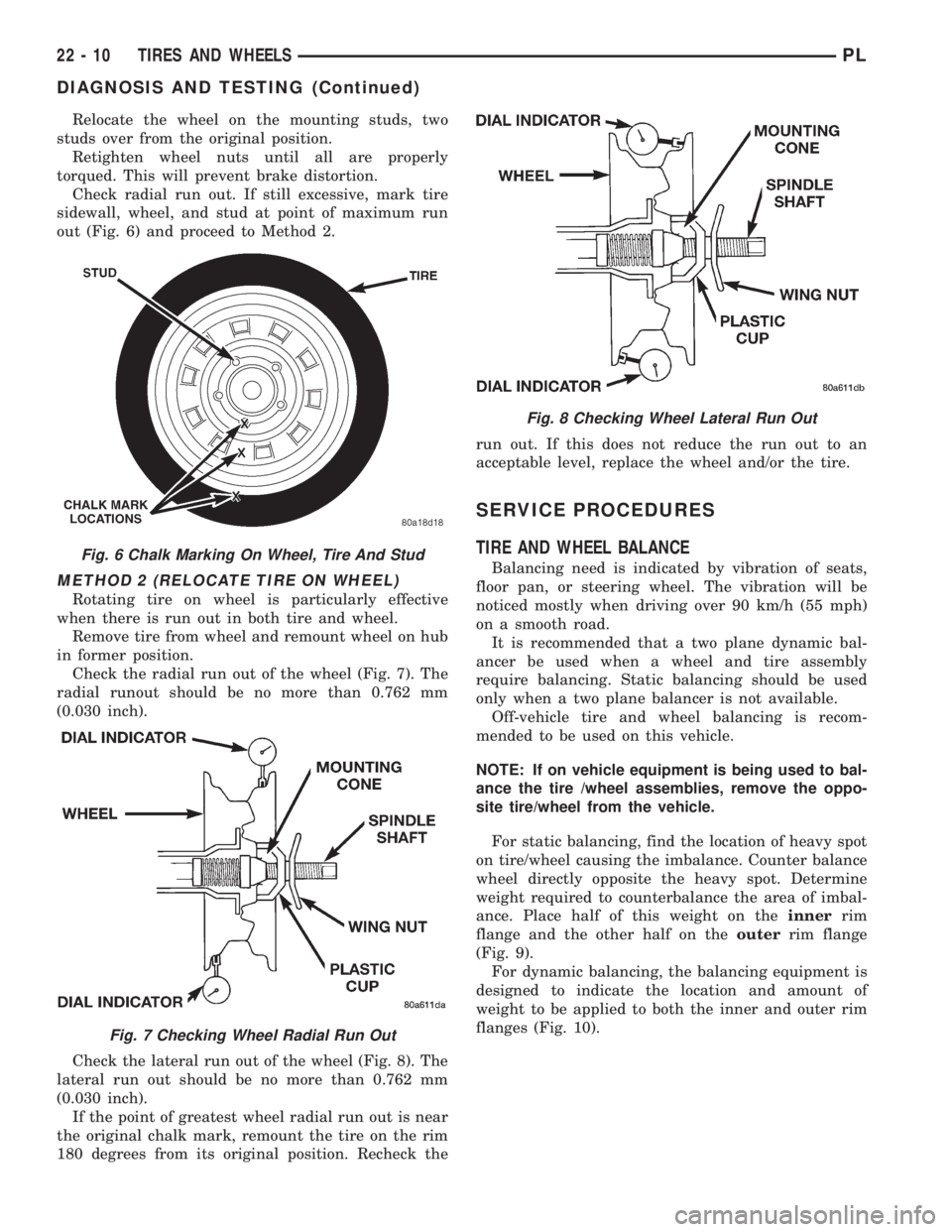
Check radial run out. If still excessive, mark tire
sidewall, wheel, and stud at point of maximum run
out (Fig. 6) and proceed to Method 2.
METHOD 2 (RELOCATE TIRE ON WHEEL)
Rotating tire on wheel is particularly effective
when there is run out in both tire and wheel.
Remove tire from wheel and remount wheel on hub
in former position.
Check the radial run out of the wheel (Fig. 7). The
radial runout should be no more than 0.762 mm
(0.030 inch).
Check the lateral run out of the wheel (Fig. 8). The
lateral run out should be no more than 0.762 mm
(0.030 inch).
If the point of greatest wheel radial run out is near
the original chalk mark, remount the tire on the rim
180 degrees from its original position. Recheck therun out. If this does not reduce the run out to an
acceptable level, replace the wheel and/or the tire.
SERVICE PROCEDURES
TIRE AND WHEEL BALANCE
Balancing need is indicated by vibration of seats,
floor pan, or steering wheel. The vibration will be
noticed mostly when driving over 90 km/h (55 mph)
on a smooth road.
It is recommended that a two plane dynamic bal-
ancer be used when a wheel and tire assembly
require balancing. Static balancing should be used
only when a two plane balancer is not available.
Off-vehicle tire and wheel balancing is recom-
mended to be used on this vehicle.
NOTE: If on vehicle equipment is being used to bal-
ance the tire /wheel assemblies, remove the oppo-
site tire/wheel from the vehicle.
For static balancing, find the location of heavy spot
on tire/wheel causing the imbalance. Counter balance
wheel directly opposite the heavy spot. Determine
weight required to counterbalance the area of imbal-
ance. Place half of this weight on theinnerrim
flange and the other half on theouterrim flange
(Fig. 9).
For dynamic balancing, the balancing equipment is
designed to indicate the location and amount of
weight to be applied to both the inner and outer rim
flanges (Fig. 10).Fig. 6 Chalk Marking On Wheel, Tire And Stud
Fig. 7 Checking Wheel Radial Run Out
Fig. 8 Checking Wheel Lateral Run Out
22 - 10 TIRES AND WHEELSPL
DIAGNOSIS AND TESTING (Continued)