1999 DODGE NEON weight
[x] Cancel search: weightPage 802 of 1200
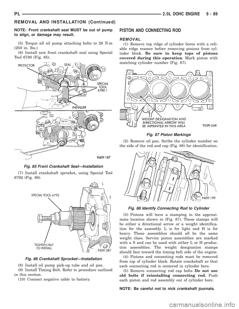
NOTE: Front crankshaft seal MUST be out of pump
to align, or damage may result.
(5) Torque all oil pump attaching bolts to 28 N´m
(250 in. lbs.)
(6) Install new front crankshaft seal using Special
Tool 6780 (Fig. 85).
(7) Install crankshaft sprocket, using Special Tool
6792 (Fig. 86).
(8) Install oil pump pick-up tube and oil pan.
(9) Install Timing Belt. Refer to procedure outlined
in this section.
(10) Connect negative cable to battery.PISTON AND CONNECTING ROD
REMOVAL
(1) Remove top ridge of cylinder bores with a reli-
able ridge reamer before removing pistons from cyl-
inder block.Be sure to keep tops of pistons
covered during this operation. Mark piston with
matching cylinder number (Fig. 87).
(2) Remove oil pan. Scribe the cylinder number on
the side of the rod and cap (Fig. 88) for identification.
(3) Pistons will have a stamping in the approxi-
mate location shown in (Fig. 87). These stamps will
be either a directional arrow or a weight identifica-
tion for the assembly. L is for light and H is for
heavy. These assemblies should all be the same
weight class. Service piston assemblies are marked
with a S and can be used with either L or H produc-
tion assemblies. The weight designation stamps
should face toward the timing belt side of the engine.
(4) Pistons and connecting rods must be removed
from top of cylinder block. Rotate crankshaft so that
each connecting rod is centered in cylinder bore.
(5) Remove connecting rod cap boltsDo not use
old bolts if reinstalling connecting rod.Push
each piston and rod assembly out of cylinder bore.
NOTE: Be careful not to nick crankshaft journals.
Fig. 85 Front Crankshaft SealÐInstallation
Fig. 86 Crankshaft SprocketÐInstallation
Fig. 87 Piston Markings
Fig. 88 Identify Connecting Rod to Cylinder
PL2.0L DOHC ENGINE 9 - 89
REMOVAL AND INSTALLATION (Continued)
Page 804 of 1200
ring gaps are staggered so that neither is in line with
oil ring rail gap.
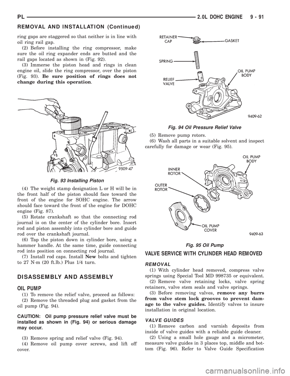
(2) Before installing the ring compressor, make
sure the oil ring expander ends are butted and the
rail gaps located as shown in (Fig. 92).
(3) Immerse the piston head and rings in clean
engine oil, slide the ring compressor, over the piston
(Fig. 93).Be sure position of rings does not
change during this operation.
(4) The weight stamp designation L or H will be in
the front half of the piston should face toward the
front of the engine for SOHC engine. The arrow
should face toward the front of the engine for DOHC
engine (Fig. 87).
(5) Rotate crankshaft so that the connecting rod
journal is on the center of the cylinder bore. Insert
rod and piston assembly into cylinder bore and guide
rod over the crankshaft journal.
(6) Tap the piston down in cylinder bore, using a
hammer handle. At the same time, guide connecting
rod into position on connecting rod journal.
(7) Install rod caps. InstallNewbolts and tighten
to 27 N´m (20 ft.lb.) Plus 1/4 turn.
DISASSEMBLY AND ASSEMBLY
OIL PUMP
(1) To remove the relief valve, proceed as follows:
(2) Remove the threaded plug and gasket from the
oil pump (Fig. 94).
CAUTION: Oil pump pressure relief valve must be
installed as shown in (Fig. 94) or serious damage
may occur.
(3) Remove spring and relief valve (Fig. 94).
(4) Remove oil pump cover screws, and lift off
cover.(5) Remove pump rotors.
(6) Wash all parts in a suitable solvent and inspect
carefully for damage or wear (Fig. 95).
VALVE SERVICE WITH CYLINDER HEAD REMOVED
REMOVAL
(1) With cylinder head removed, compress valve
springs using Special Tool MD 998735 or equivalent.
(2) Remove valve retaining locks, valve spring
retainers, valve stem seals and valve springs.
(3) Before removing valves,remove any burrs
from valve stem lock grooves to prevent dam-
age to the valve guides.Identify valves to insure
installation in original location.
VALVE GUIDES
(1) Remove carbon and varnish deposits from
inside of valve guides with a reliable guide cleaner.
(2) Using a small hole gauge and a micrometer,
measure valve guides in 3 places top, middle and bot-
tom (Fig. 96). Refer to Valve Guide Specification
Fig. 93 Installing Piston
Fig. 94 Oil Pressure Relief Valve
Fig. 95 Oil Pump
PL2.0L DOHC ENGINE 9 - 91
REMOVAL AND INSTALLATION (Continued)
Page 809 of 1200
CYLINDER BLOCK AND BORE
(1) Clean cylinder block thoroughly and check all
core hole plugs for evidence of leaking.
(2) If new core plugs are installed, Refer to Engine
Core Plugs outlined in this section.
(3) Examine block and cylinder bores for cracks or
fractures.
CYLINDER BORE INSPECTION
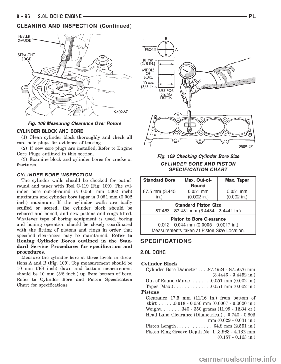
The cylinder walls should be checked for out-of-
round and taper with Tool C-119 (Fig. 109). The cyl-
inder bore out-of-round is 0.050 mm (.002 inch)
maximum and cylinder bore taper is 0.051 mm (0.002
inch) maximum. If the cylinder walls are badly
scuffed or scored, the cylinder block should be
rebored and honed, and new pistons and rings fitted.
Whatever type of boring equipment is used, boring
and honing operation should be closely coordinated
with the fitting of pistons and rings in order that
specified clearances may be maintained.Refer to
Honing Cylinder Bores outlined in the Stan-
dard Service Procedures for specification and
procedures.
Measure the cylinder bore at three levels in direc-
tions A and B (Fig. 109). Top measurement should be
10 mm (3/8 inch) down and bottom measurement
should be 10 mm (3/8 inch.) up from bottom of bore.
Refer to Cylinder Bore and Piston Specification
Chart for specifications.
SPECIFICATIONS
2.0L DOHC
Cylinder Block
Cylinder Bore Diameter. . . .87.4924 - 87.5076 mm
(3.4446 - 3.4452 in.)
Out-of-Round (Max.)........0.051 mm (0.002 in.)
Taper (Max.)..............0.051 mm (0.002 in.)
Pistons
Clearance 17.5 mm (11/16 in.) from bottom of
skirt......0.018 - 0.050 mm (0.0007 - 0.0020 in.)
Weight........340 - 350 grams (11.99 - 12.34 oz.)
Head Land Clearance (Diametrical) . .0.740 - 0.803
mm (0.029 - 0.031 in.)
Piston Length..............64.8 mm (2.551 in.)
Piston Ring Groove Depth No. 1 .3.983 - 4.132 mm
(0.157 - 0.163 in.)
Fig. 108 Measuring Clearance Over Rotors
Fig. 109 Checking Cylinder Bore Size
CYLINDER BORE AND PISTON
SPECIFICATION CHART
Standard Bore Max. Out-of-
RoundMax. Taper
87.5 mm (3.445
in.)0.051 mm
(0.002 in.)0.051 mm
(0.002 in.)
Standard Piston Size
87.463 - 87.481 mm (3.4434 - 3.4441 in.)
Piston to Bore Clearance
0.012 - 0.044 mm (0.0005 - 0.0017 in.)
Measurements taken at Piston Size Location.
9 - 96 2.0L DOHC ENGINEPL
CLEANING AND INSPECTION (Continued)
Page 810 of 1200
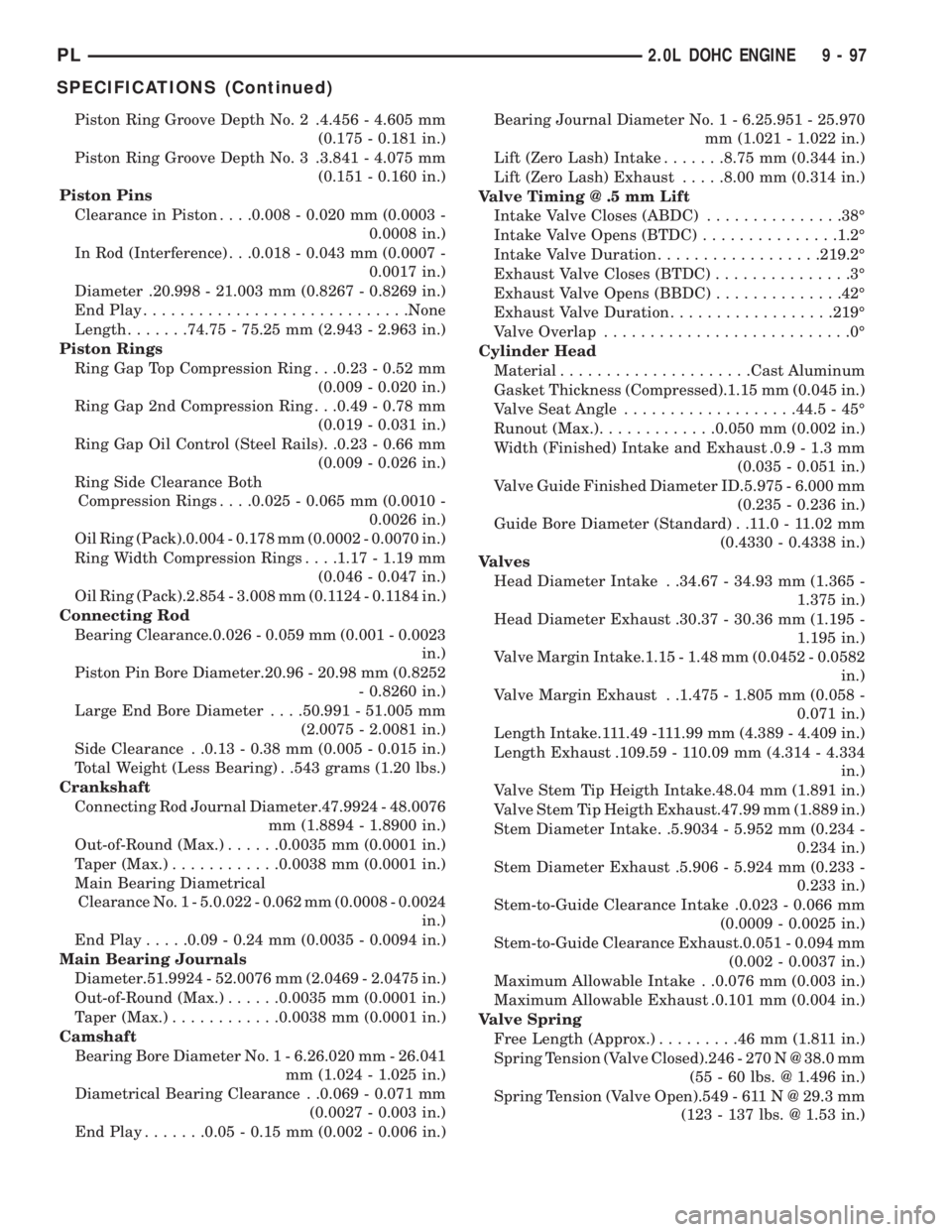
Piston Ring Groove Depth No. 2 .4.456 - 4.605 mm
(0.175 - 0.181 in.)
Piston Ring Groove Depth No. 3 .3.841 - 4.075 mm
(0.151 - 0.160 in.)
Piston Pins
Clearance in Piston. . . .0.008 - 0.020 mm (0.0003 -
0.0008 in.)
In Rod (Interference) . . .0.018 - 0.043 mm (0.0007 -
0.0017 in.)
Diameter .20.998 - 21.003 mm (0.8267 - 0.8269 in.)
End Play.............................None
Length.......74.75 - 75.25 mm (2.943 - 2.963 in.)
Piston Rings
Ring Gap Top Compression Ring . . .0.23 - 0.52 mm
(0.009 - 0.020 in.)
Ring Gap 2nd Compression Ring . . .0.49 - 0.78 mm
(0.019 - 0.031 in.)
Ring Gap Oil Control (Steel Rails). .0.23 - 0.66 mm
(0.009 - 0.026 in.)
Ring Side Clearance Both
Compression Rings. . . .0.025 - 0.065 mm (0.0010 -
0.0026 in.)
Oil Ring (Pack).0.004 - 0.178 mm (0.0002 - 0.0070 in.)
Ring Width Compression Rings. . . .1.17 - 1.19 mm
(0.046 - 0.047 in.)
Oil Ring (Pack).2.854 - 3.008 mm (0.1124 - 0.1184 in.)
Connecting Rod
Bearing Clearance.0.026 - 0.059 mm (0.001 - 0.0023
in.)
Piston Pin Bore Diameter.20.96 - 20.98 mm (0.8252
- 0.8260 in.)
Large End Bore Diameter. . . .50.991 - 51.005 mm
(2.0075 - 2.0081 in.)
Side Clearance . .0.13 - 0.38 mm (0.005 - 0.015 in.)
Total Weight (Less Bearing) . .543 grams (1.20 lbs.)
Crankshaft
Connecting Rod Journal Diameter.47.9924 - 48.0076
mm (1.8894 - 1.8900 in.)
Out-of-Round (Max.)......0.0035 mm (0.0001 in.)
Taper (Max.)............0.0038 mm (0.0001 in.)
Main Bearing Diametrical
Clearance No. 1 - 5.0.022 - 0.062 mm (0.0008 - 0.0024
in.)
End Play.....0.09 - 0.24 mm (0.0035 - 0.0094 in.)
Main Bearing Journals
Diameter.51.9924 - 52.0076 mm (2.0469 - 2.0475 in.)
Out-of-Round (Max.)......0.0035 mm (0.0001 in.)
Taper (Max.)............0.0038 mm (0.0001 in.)
Camshaft
Bearing Bore Diameter No. 1 - 6.26.020 mm - 26.041
mm (1.024 - 1.025 in.)
Diametrical Bearing Clearance . .0.069 - 0.071 mm
(0.0027 - 0.003 in.)
End Play.......0.05 - 0.15 mm (0.002 - 0.006 in.)Bearing Journal Diameter No. 1 - 6.25.951 - 25.970
mm (1.021 - 1.022 in.)
Lift (Zero Lash) Intake.......8.75 mm (0.344 in.)
Lift (Zero Lash) Exhaust.....8.00 mm (0.314 in.)
Valve Timing @ .5 mm Lift
Intake Valve Closes (ABDC)...............38É
Intake Valve Opens (BTDC)...............1.2É
Intake Valve Duration..................219.2É
Exhaust Valve Closes (BTDC)...............3É
Exhaust Valve Opens (BBDC)..............42É
Exhaust Valve Duration..................219É
Valve Overlap...........................0É
Cylinder Head
Material.....................Cast Aluminum
Gasket Thickness (Compressed).1.15 mm (0.045 in.)
Valve Seat Angle...................44.5 - 45É
Runout (Max.).............0.050 mm (0.002 in.)
Width (Finished) Intake and Exhaust .0.9 - 1.3 mm
(0.035 - 0.051 in.)
Valve Guide Finished Diameter ID.5.975 - 6.000 mm
(0.235 - 0.236 in.)
Guide Bore Diameter (Standard) . .11.0 - 11.02 mm
(0.4330 - 0.4338 in.)
Valves
Head Diameter Intake . .34.67 - 34.93 mm (1.365 -
1.375 in.)
Head Diameter Exhaust .30.37 - 30.36 mm (1.195 -
1.195 in.)
Valve Margin Intake.1.15 - 1.48 mm (0.0452 - 0.0582
in.)
Valve Margin Exhaust . .1.475 - 1.805 mm (0.058 -
0.071 in.)
Length Intake.111.49 -111.99 mm (4.389 - 4.409 in.)
Length Exhaust .109.59 - 110.09 mm (4.314 - 4.334
in.)
Valve Stem Tip Heigth Intake.48.04 mm (1.891 in.)
Valve Stem Tip Heigth Exhaust.47.99 mm (1.889 in.)
Stem Diameter Intake. .5.9034 - 5.952 mm (0.234 -
0.234 in.)
Stem Diameter Exhaust .5.906 - 5.924 mm (0.233 -
0.233 in.)
Stem-to-Guide Clearance Intake .0.023 - 0.066 mm
(0.0009 - 0.0025 in.)
Stem-to-Guide Clearance Exhaust.0.051 - 0.094 mm
(0.002 - 0.0037 in.)
Maximum Allowable Intake . .0.076 mm (0.003 in.)
Maximum Allowable Exhaust .0.101 mm (0.004 in.)
Valve Spring
Free Length (Approx.).........46mm(1.811 in.)
Spring Tension (Valve Closed).246 - 270 N @ 38.0 mm
(55 - 60 lbs. @ 1.496 in.)
Spring Tension (Valve Open).549 - 611 N @ 29.3 mm
(123 - 137 lbs. @ 1.53 in.)
PL2.0L DOHC ENGINE 9 - 97
SPECIFICATIONS (Continued)
Page 815 of 1200
ENGINE 1.8L SOHC
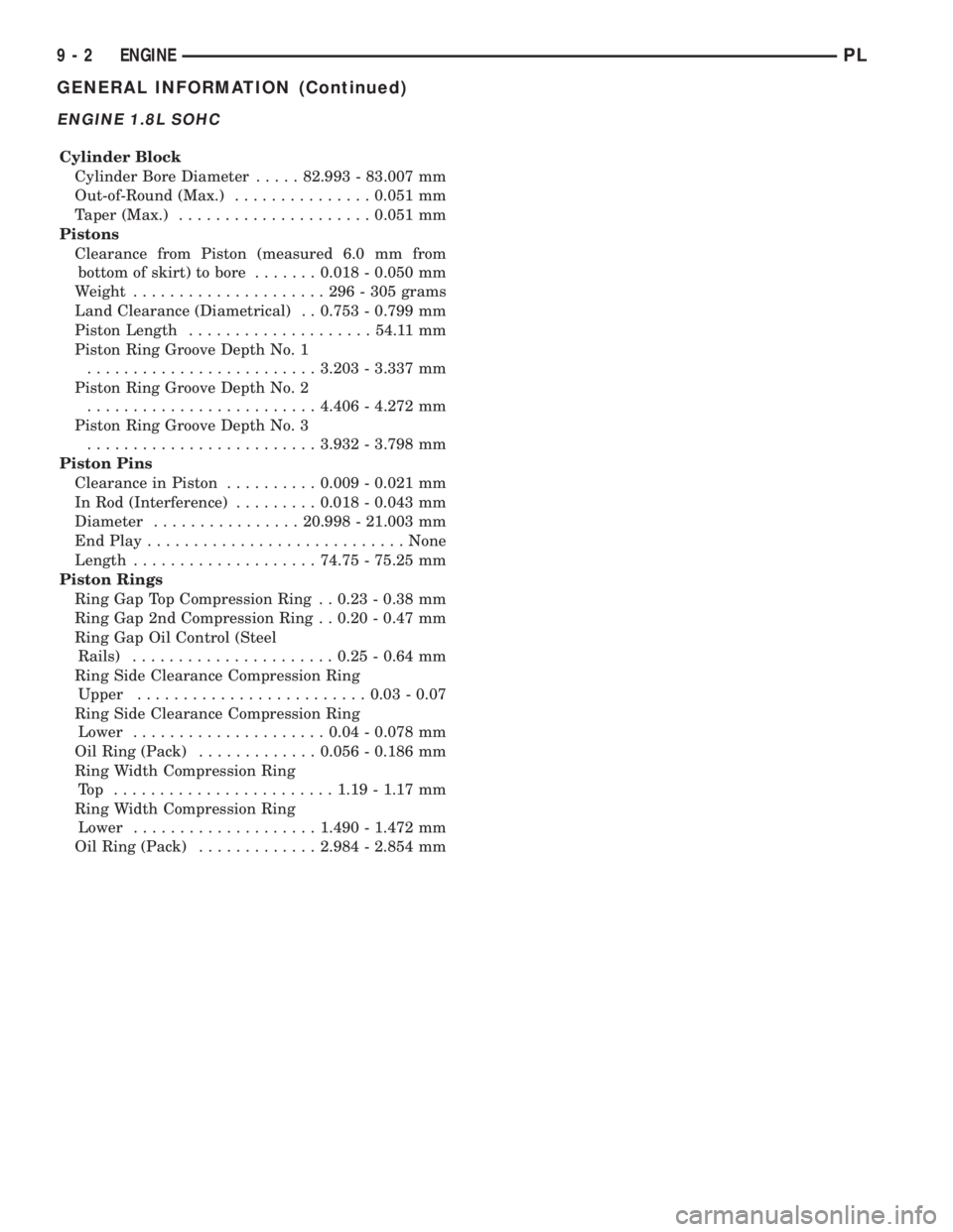
Cylinder Block
Cylinder Bore Diameter.....82.993 - 83.007 mm
Out-of-Round (Max.)...............0.051 mm
Taper (Max.).....................0.051 mm
Pistons
Clearance from Piston (measured 6.0 mm from
bottom of skirt) to bore.......0.018 - 0.050 mm
Weight.....................296-305grams
Land Clearance (Diametrical) . . 0.753 - 0.799 mm
Piston Length....................54.11 mm
Piston Ring Groove Depth No. 1
.........................3.203 - 3.337 mm
Piston Ring Groove Depth No. 2
.........................4.406 - 4.272 mm
Piston Ring Groove Depth No. 3
.........................3.932 - 3.798 mm
Piston Pins
Clearance in Piston..........0.009 - 0.021 mm
In Rod (Interference).........0.018 - 0.043 mm
Diameter................20.998 - 21.003 mm
End Play............................None
Length....................74.75 - 75.25 mm
Piston Rings
Ring Gap Top Compression Ring . . 0.23 - 0.38 mm
Ring Gap 2nd Compression Ring . . 0.20 - 0.47 mm
Ring Gap Oil Control (Steel
Rails)......................0.25 - 0.64 mm
Ring Side Clearance Compression Ring
Upper.........................0.03 - 0.07
Ring Side Clearance Compression Ring
Lower.....................0.04 - 0.078 mm
Oil Ring (Pack).............0.056 - 0.186 mm
Ring Width Compression Ring
Top ........................1.19 - 1.17 mm
Ring Width Compression Ring
Lower....................1.490 - 1.472 mm
Oil Ring (Pack).............2.984 - 2.854 mm
9 - 2 ENGINEPL
GENERAL INFORMATION (Continued)
Page 820 of 1200
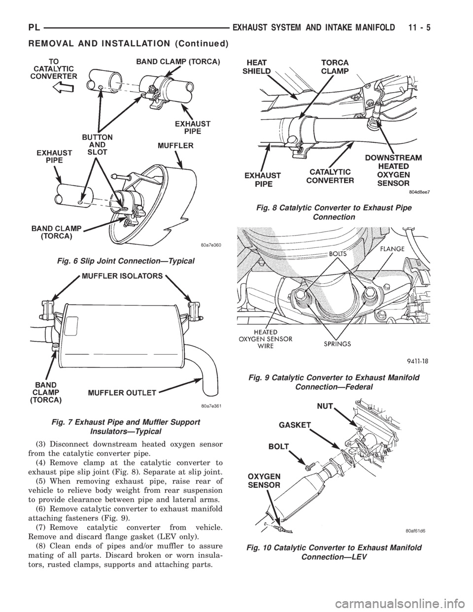
(3) Disconnect downstream heated oxygen sensor
from the catalytic converter pipe.
(4) Remove clamp at the catalytic converter to
exhaust pipe slip joint (Fig. 8). Separate at slip joint.
(5) When removing exhaust pipe, raise rear of
vehicle to relieve body weight from rear suspension
to provide clearance between pipe and lateral arms.
(6) Remove catalytic converter to exhaust manifold
attaching fasteners (Fig. 9).
(7) Remove catalytic converter from vehicle.
Remove and discard flange gasket (LEV only).
(8) Clean ends of pipes and/or muffler to assure
mating of all parts. Discard broken or worn insula-
tors, rusted clamps, supports and attaching parts.
Fig. 6 Slip Joint ConnectionÐTypical
Fig. 7 Exhaust Pipe and Muffler Support
InsulatorsÐTypical
Fig. 8 Catalytic Converter to Exhaust Pipe
Connection
Fig. 9 Catalytic Converter to Exhaust Manifold
ConnectionÐFederal
Fig. 10 Catalytic Converter to Exhaust Manifold
ConnectionÐLEV
PLEXHAUST SYSTEM AND INTAKE MANIFOLD 11 - 5
REMOVAL AND INSTALLATION (Continued)
Page 852 of 1200
The hose clamps have rolled edges to prevent the
clamp from cutting into the hose. Only use clamps
that are original equipment or equivalent. Other
types of clamps may cut into the hoses and cause
high pressure fuel leaks. Tighten hose clamps to 1
N´m (10 in. lbs.) torque.
QUICK-CONNECT FITTINGS
REMOVAL
When disconnecting a quick-connect fitting, the
retainer will remain on the fuel tube nipple.
WARNING: RELEASE FUEL SYSTEM PRESSURE
BEFORE DISCONNECTING A QUICK-CONNECT FIT-
TINGS. REFER TO THE FUEL PRESSURE RELEASE
PROCEDURE.
(1) Disconnect negative cable from battery.
(2) Perform Fuel Pressure Release Procedure.
Refer to the Fuel Pressure Release Procedure in this
section.
(3) Squeeze retainer tabs together and pull fuel
tube/quick-connect fitting assembly off of fuel tube
nipple. The retainer will remain on fuel tube.
INSTALLATION
CAUTION: Never install a quick-connect fitting
without the retainer being either on the fuel tube or
already in the quick-connect fitting. In either case,
ensure the retainer locks securely into the quick-
connect fitting by firmly pulling on fuel tube and fit-
ting to ensure it is secured.
(1) Using a clean lint free cloth, clean the fuel tube
nipple and retainer.
(2) Prior to connecting the fitting to the fuel tube,
coat the fuel tube nipple with clean 30 weight engine
oil.
(3) Push the quick-connect fitting over the fuel
tube until theretainer seats and a click is heard.
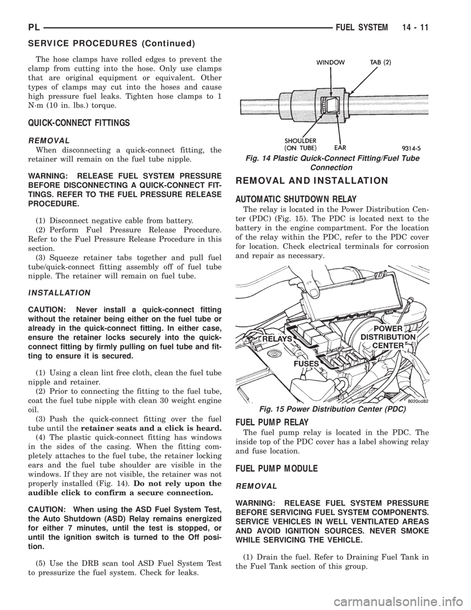
(4) The plastic quick-connect fitting has windows
in the sides of the casing. When the fitting com-
pletely attaches to the fuel tube, the retainer locking
ears and the fuel tube shoulder are visible in the
windows. If they are not visible, the retainer was not
properly installed (Fig. 14).Do not rely upon the
audible click to confirm a secure connection.
CAUTION: When using the ASD Fuel System Test,
the Auto Shutdown (ASD) Relay remains energized
for either 7 minutes, until the test is stopped, or
until the ignition switch is turned to the Off posi-
tion.
(5) Use the DRB scan tool ASD Fuel System Test
to pressurize the fuel system. Check for leaks.
REMOVAL AND INSTALLATION
AUTOMATIC SHUTDOWN RELAY
The relay is located in the Power Distribution Cen-
ter (PDC) (Fig. 15). The PDC is located next to the
battery in the engine compartment. For the location
of the relay within the PDC, refer to the PDC cover
for location. Check electrical terminals for corrosion
and repair as necessary.
FUEL PUMP RELAY
The fuel pump relay is located in the PDC. The
inside top of the PDC cover has a label showing relay
and fuse location.
FUEL PUMP MODULE
REMOVAL
WARNING: RELEASE FUEL SYSTEM PRESSURE
BEFORE SERVICING FUEL SYSTEM COMPONENTS.
SERVICE VEHICLES IN WELL VENTILATED AREAS
AND AVOID IGNITION SOURCES. NEVER SMOKE
WHILE SERVICING THE VEHICLE.
(1) Drain the fuel. Refer to Draining Fuel Tank in
the Fuel Tank section of this group.
Fig. 14 Plastic Quick-Connect Fitting/Fuel Tube
Connection
Fig. 15 Power Distribution Center (PDC)
PLFUEL SYSTEM 14 - 11
SERVICE PROCEDURES (Continued)
Page 867 of 1200

CRANKSHAFT POSITION SENSORÐPCM INPUT
The PCM determines what cylinder to fire from the
crankshaft position sensor input and the camshaft
position sensor input. The second crankshaft counter-
weight has two sets of four timing reference notches
including a 60 degree signature notch (Fig. 7). From
the crankshaft position sensor input the PCM deter-
mines engine speed and crankshaft angle (position).
The notches generate pulses from high to low in
the crankshaft position sensor output voltage. When
a metal portion of the counterweight aligns with the
crankshaft position sensor, the sensor output voltage
goes low (less than 0.5 volts). When a notch aligns
with the sensor, voltage goes high (5.0 volts). As a
group of notches pass under the sensor, the outputvoltage switches from low (metal) to high (notch)
then back to low.
If available, an oscilloscope can display the square
wave patterns of each voltage pulses. From the width
of the output voltage pulses, the PCM calculates
engine speed. The width of the pulses represent the
amount of time the output voltage stays high before
switching back to low. The period of time the sensor
output voltage stays high before switching back to
low is referred to as pulse width. The faster the
engine is operating, the smaller the pulse width on
the oscilloscope.
By counting the pulses and referencing the pulse
from the 60 degree signature notch, the PCM calcu-
lates crankshaft angle (position). In each group of
timing reference notches, the first notch represents
69 degrees before top dead center (BTDC). The sec-
ond notch represents 49 degrees BTDC. The third
notch represents 29 degrees. The last notch in each
set represents 9 degrees before top dead center
(TDC).
The timing reference notches are machined at 20É
increments. From the voltage pulse width the PCM
tells the difference between the timing reference
notches and the 60 degree signature notch. The 60
degree signature notch produces a longer pulse width
than the smaller timing reference notches. If the
camshaft position sensor input switches from high to
low when the 60 degree signature notch passes under
the crankshaft position sensor, the PCM knows cylin-
der number one is the next cylinder at TDC.
The crankshaft position sensor mounts to the
engine block behind the alternator, just above the oil
filter (Fig. 8).
ENGINE COOLANT TEMPERATURE SENSORÐPCM
INPUT
The combination coolant temperature sensor has
two elements. One element supplies coolant temper-
ature signal to the PCM. The other element supplies
coolant temperature signal to the instrument panel
gauge cluster. The PCM determines engine coolant
temperature from the coolant temperature sensor.
As coolant temperature varies the coolant temper-
ature sensors resistance changes resulting in a differ-
ent input voltage to the PCM and the instrument
panel gauge cluster.
When the engine is cold, the PCM will provide
slightly richer air- fuel mixtures and higher idle
speeds until normal operating temperatures are
reached.
SOHC
The coolant sensor threads into the rear of the cyl-
inder head, next to the camshaft position sensor (Fig.
9). New sensors have sealant applied to the threads.
Fig. 5 Target MagnetÐTypical
Fig. 6 Target Magnet Polarity
14 - 26 FUEL SYSTEMPL
DESCRIPTION AND OPERATION (Continued)