1999 DODGE NEON weight
[x] Cancel search: weightPage 54 of 1200

Inspect the tension strut for signs of contact with
the ground or road debris which has bent or caused
other damage to the tension strut. If the tension
strut is bent or damaged the tension strut will
require replacement.Do not attempt to repair or
straighten a tension strut.
STABILIZER BAR AND BUSHINGS
Inspect the stabilizer bar for damage or bending.
Inspect for broken or distorted stabilizer bar bush-
ings, bushing retainers, and worn or damaged stabi-
lizer bar to strut attaching links. If stabiizer bar to
rear frame rail bushing replacement is required,
bushings can be removed from sway bar by opening
slit and peeling bushing off sway bar.
STABILIZER BAR ATTACHING LINKS
Inspect the bushings and sleeves in the stabilizer
bar attaching links for damage or deterioration.
Inspect the stabilizer bar attaching link to ensure it
is not bent or broken. If any of these conditions are
present when inspecting the attaching links, replace-
ment of the attaching link is required.
SERVICE PROCEDURES
REAR WHEEL ALIGNMENT
Refer to Front And Rear Wheel Toe Setting Proce-
dures in the Wheel Alignment Check And Adjustment
section in this group of the service manual for the
required rear wheel Toe setting procedure.
REMOVAL AND INSTALLATION
STRUT ASSEMBLY
REMOVE
(1) Raise vehicle on jackstands or centered on a
frame contact type hoist. See Hoisting in the Lubri-
cation and Maintenance section of this manual, for
the required lifting procedure to be used for this
vehicle.
(2) Remove the rear wheel and tire assembly from
the vehicle.
(3) Remove hydraulic flex hose bracket, from
bracket on rear strut assembly (Fig. 6). If vehicle is
equipped with Anti-Lock brakes, the wheel speed
sensor cable routing clip is also attached to the strut
assembly bracket.
(4) Support rear knuckle, suspension and brake
components of vehicle before removing clevis bracket
to knuckle attaching bolts.Do not let weight of
rear knuckle and assembled components hang
unsupported when strut is removed.CAUTION: The knuckle to strut assembly attaching
bolts are serrated and must not be turned during
removal. Remove nuts while holding bolts station-
ary in knuckle.
(5) Remove the 2 clevis bracket bolts (Fig. 7)
attaching strut assembly to rear knuckle.
(6) Lower vehicle. Access to rear upper strut
mount to strut tower attaching bolts, is through the
trunk of the vehicle.
Fig. 6 Hydraulic Flex Hose Bracket Attachment To
Strut
Fig. 7 Knuckle To Clevis Bracket Bolts
PLSUSPENSION 2 - 43
DIAGNOSIS AND TESTING (Continued)
Page 57 of 1200

sequence until all nuts are torqued to half specifica-
tion. Then repeat the tightening sequence to the full
specified torque of 129 N´m (95 ft. lbs.).
(5) Lower the vehicle to the ground.
(6) With suspension supporting the full weight of
the vehicle, securely tighten the stabilizer bar
retainer to frame rail attaching bolts (Fig. 11).
KNUCKLE
REMOVE
(1) Raise vehicle on jackstands or centered on a
frame contact type hoist. See Hoisting in the Lubri-
cation and Maintenance section of this manual, for
the required lifting procedure to be used for this
vehicle.
(2) Remove the rear wheel and tire.
(3) If vehicle is equipped with rear disc brakes,
remove the rear caliper from the adapter. Refer to
Rear Disk Brakes in Group 5 Brakes of this Service
manual for required caliper removal procedure. After
removing the caliper, store the caliper by hanging it
from frame of the vehicle (Fig. 14). Do not let weight
of rear caliper hang from flexible brake hose.
(4) If vehicle is equipped with rear disc brakes,
remove rotor from hub. If vehicle is equipped with
rear drum brakes, remove brake drum from hub.
(5) If vehicle is equipped with ABS brakes, remove
wheel speed sensor from rear disc brake adapter
(Fig. 15).
(6) Remove rear hub/bearing retaining nut (Fig.
16). Then remove the hub/bearing from the knuckle.(7) If vehicle is equipped with rear drum brakes
remove the 4 bolts (Fig. 17) attaching rear brake sup-
port plate to knuckle. Then remove brake support
plate, brake shoes and wheel cylinder as an assembly
from rear knuckle (Fig. 17).It is not necessary to
remove brake flex hose from wheel cylinder
when removing support plate.Brake support
plate when removed, must be supported in same
manner as caliper assembly.
(8) On vehicles equipped with rear disc brakes,
remove the 4 bolts attaching disc brake adapter to
rear knuckle (Fig. 18). Then remove the adapter,
rotor shield, park brake shoes and park brake cable
as an assembly from knuckle.
CAUTION: The knuckle to strut assembly attaching
bolts are serrated and must not be turned during
removal. Loosen and remove nuts while holding
bolts stationary in knuckle.
Fig. 14 Storing Rear Caliper
Fig. 15 Speed Sensor Head Attachment To Disc
Brake Adapter
Fig. 16 Hub/ Bearing Retaining Nut
2 - 46 SUSPENSIONPL
REMOVAL AND INSTALLATION (Continued)
Page 59 of 1200

(4) Install tension strut bushing, tension strut
retainer and nut on tension strut (Fig. 21).When
installing tension strut retainers, the retainers
must be installed on tension strut, with cupped
side of retainer facing away from bushing and
knuckle (Fig. 21).
(5) Position a large adjustable wrench on flat of
tension strut to keep it from turning, (Fig. 22) and
then torque tension strut nut to 95 N´m (70 ft. lbs.).
(6) On vehicles equipped with rear drum brakes,
install rear brake support plate assembly onto the
knuckle (Fig. 17). Install the 4 bolts (Fig. 17) attach-
ing rear brake support plate to rear knuckle. Torque
attaching bolts to 68 N´m (50 ft. lbs.).
(7) On vehicles equipped with rear disc brakes,
install the disc brake adapter on knuckle (Fig. 18)
Install the 4 bolts attaching the disc brake adapter to
knuckle (Fig. 18). Torque attaching bolts to 68 N´m
(50 ft. lbs.).(8) If vehicle is equipped with ABS brakes, install
speed sensor head into rear brake support plate or
disc brake adapter (Fig. 15). Tighten wheel speed
sensor mounting bolt to a torque of 7 N´m (60 in.
lbs.).
CAUTION: The hub/bearing retaining nut must be
tightened to but must not exceed its required
torque specification. The proper torque specifica-
tion of the retaining nut is critical to the life of the
hub bearing.
(9) Install rear hub and bearing assembly on
knuckle. Install hub and bearing assembly retaining
nut (Fig. 16), and torque to 217 N´m (160 ft. lbs).
(10) If vehicle is equipped with rear disc brakes,
install rear braking disc on hub. If vehicle is
equipped with rear drum brakes, install the brake
drum on hub.
(11) If vehicle is equipped with rear disc brakes,
install rear braking disc on hub. Carefully install
rear brake caliper over braking disc and install on
adapter. Tighten the caliper assembly to adapter
mounting bolts to 22 N´m (192 in. lbs.). Refer to Rear
Disc Brakes in Group 5 Brakes in this service man-
ual for required caliper installation procedure.
(12) Install wheel and tire assembly on vehicle.
Tighten the wheel mounting stud nuts in proper
sequence until all nuts are torqued to half specifica-
tion. Then repeat the tightening sequence to the full
specified torque of 135 N´m (100 ft. lbs.).
(13) Lower vehicle.
(14) With suspension supporting total weight of
vehicle, and lateral links at correct curb height,
torque both lateral link attaching bolts to 95 N´m (70
ft. lbs.).
(15) Check and reset rear wheel TOE to specifica-
tions if required. Refer to Front And Rear Toe Setting
Procedure in the Wheel Alignment Check And
Adjustment section in this group of the service man-
ual for the required Toe setting procedure.
LATERAL LINKS
The rear suspension lateral links (Fig. 23) are only
serviced as complete assemblies. The isolator bush-
ings used in the lateral links are not serviced as sep-
arate components. The rear lateral link assemblies
are unique, having different size bushings to accom-
modate the rear Toe adjustment cams. The rearward
lateral links, must be installed with small bushing
sleeve at knuckle and large bushing sleeve at rear
crossmember. This is required to accommodate the
rear Toe adjustment cam.
REMOVE
(1) Raise vehicle on jackstands or centered on a
frame contact type hoist. See Hoisting in the Lubri-
Fig. 21 Tension Strut Bushings Installed On Tension
Strut
Fig. 22 Torquing Tension Strut Nut
2 - 48 SUSPENSIONPL
REMOVAL AND INSTALLATION (Continued)
Page 61 of 1200
link mounting bolt at crossmember MUST be
installed, with head of bolt facing rear of vehi-
cle. The long attaching bolt must be used at
rear crossmember and short bolt used at
knuckle.
(1) Install washer on short lateral link attaching
bolt. Then install short lateral link attaching bolt,
into lateral link having the same size bushing
sleeves. Then install lateral link, bolt and washer
onto knuckle as an assembly, with head of bolt facing
to front of vehicle (Fig. 24).
(2) Install lateral link with small and large bush-
ing sleeve, on lateral link attaching bolt in rear
knuckle (Fig. 24).Small bushing sleeve must be
installed on bolt in rear knuckle with large
bushing sleeve at crossmember of vehicle.
(3) Install washer and nut onto lateral link attach-
ing bolt at rear knuckle (Fig. 24).Do not tighten
the lateral link to rear knuckle attaching bolt
at this time.
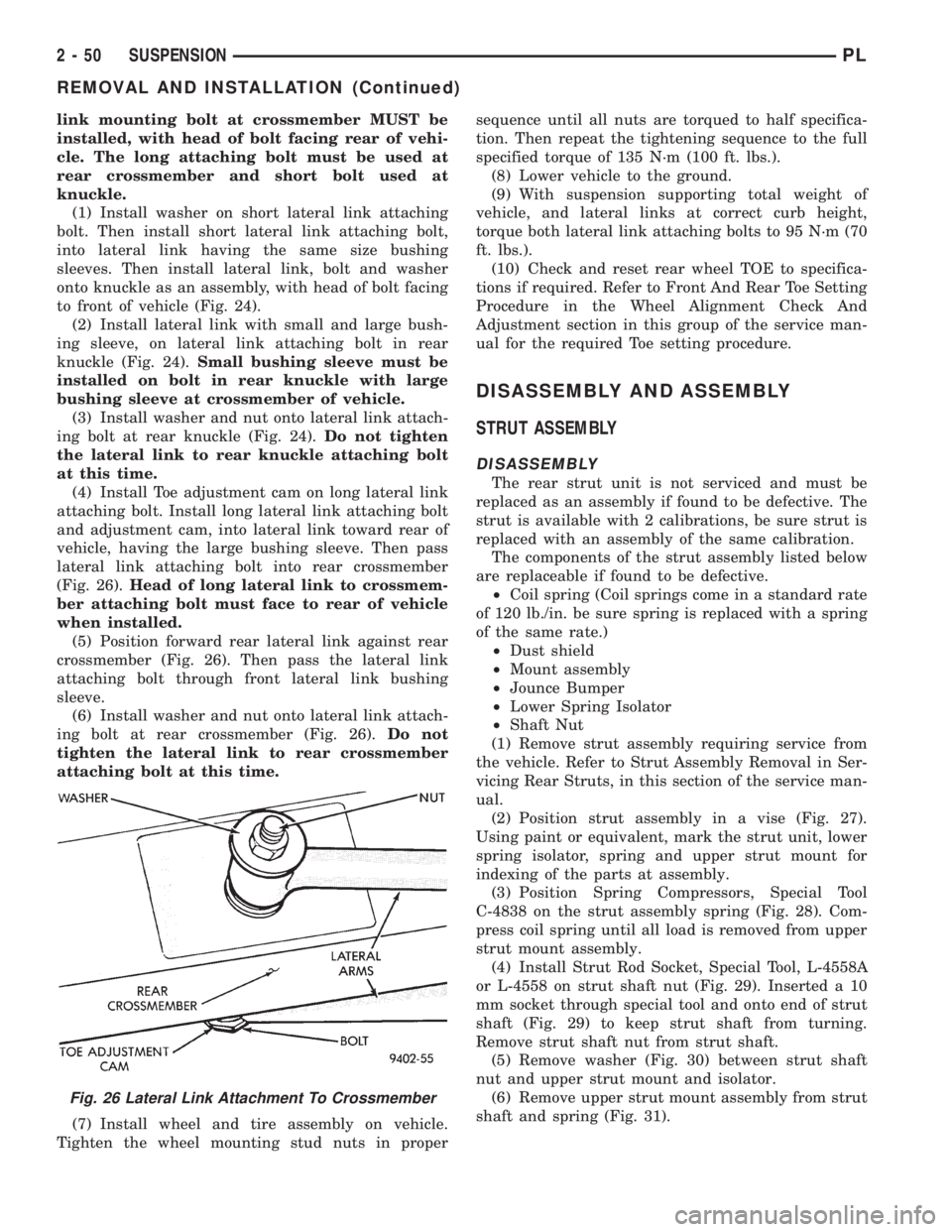
(4) Install Toe adjustment cam on long lateral link
attaching bolt. Install long lateral link attaching bolt
and adjustment cam, into lateral link toward rear of
vehicle, having the large bushing sleeve. Then pass
lateral link attaching bolt into rear crossmember
(Fig. 26).Head of long lateral link to crossmem-
ber attaching bolt must face to rear of vehicle
when installed.
(5) Position forward rear lateral link against rear
crossmember (Fig. 26). Then pass the lateral link
attaching bolt through front lateral link bushing
sleeve.
(6) Install washer and nut onto lateral link attach-
ing bolt at rear crossmember (Fig. 26).Do not
tighten the lateral link to rear crossmember
attaching bolt at this time.
(7) Install wheel and tire assembly on vehicle.
Tighten the wheel mounting stud nuts in propersequence until all nuts are torqued to half specifica-
tion. Then repeat the tightening sequence to the full
specified torque of 135 N´m (100 ft. lbs.).
(8) Lower vehicle to the ground.
(9) With suspension supporting total weight of
vehicle, and lateral links at correct curb height,
torque both lateral link attaching bolts to 95 N´m (70
ft. lbs.).
(10) Check and reset rear wheel TOE to specifica-
tions if required. Refer to Front And Rear Toe Setting
Procedure in the Wheel Alignment Check And
Adjustment section in this group of the service man-
ual for the required Toe setting procedure.
DISASSEMBLY AND ASSEMBLY
STRUT ASSEMBLY
DISASSEMBLY
The rear strut unit is not serviced and must be
replaced as an assembly if found to be defective. The
strut is available with 2 calibrations, be sure strut is
replaced with an assembly of the same calibration.
The components of the strut assembly listed below
are replaceable if found to be defective.
²Coil spring (Coil springs come in a standard rate
of 120 lb./in. be sure spring is replaced with a spring
of the same rate.)
²Dust shield
²Mount assembly
²Jounce Bumper
²Lower Spring Isolator
²Shaft Nut
(1) Remove strut assembly requiring service from
the vehicle. Refer to Strut Assembly Removal in Ser-
vicing Rear Struts, in this section of the service man-
ual.
(2) Position strut assembly in a vise (Fig. 27).
Using paint or equivalent, mark the strut unit, lower
spring isolator, spring and upper strut mount for
indexing of the parts at assembly.
(3) Position Spring Compressors, Special Tool
C-4838 on the strut assembly spring (Fig. 28). Com-
press coil spring until all load is removed from upper
strut mount assembly.
(4) Install Strut Rod Socket, Special Tool, L-4558A
or L-4558 on strut shaft nut (Fig. 29). Inserted a 10
mm socket through special tool and onto end of strut
shaft (Fig. 29) to keep strut shaft from turning.
Remove strut shaft nut from strut shaft.
(5) Remove washer (Fig. 30) between strut shaft
nut and upper strut mount and isolator.
(6) Remove upper strut mount assembly from strut
shaft and spring (Fig. 31).
Fig. 26 Lateral Link Attachment To Crossmember
2 - 50 SUSPENSIONPL
REMOVAL AND INSTALLATION (Continued)
Page 66 of 1200
DIFFERENTIAL AND DRIVELINE
CONTENTS
page page
GENERAL INFORMATION
FRONT DRIVESHAFTS.................... 1
DIAGNOSIS AND TESTING
DRIVESHAFT DIAGNOSIS.................. 2
REMOVAL AND INSTALLATION
FRONT DRIVESHAFTS.................... 2
DISASSEMBLY AND ASSEMBLY
DRIVESHAFT RECONDITION............... 7INNER TRIPOD JOINT SEAL BOOT.......... 9
OUTER C/V JOINT SEAL BOOT............ 13
SPECIFICATIONS
TORQUE.............................. 16
SPECIAL TOOLS
DRIVESHAFT........................... 16
GENERAL INFORMATION
FRONT DRIVESHAFTS
Vehicles equipped with either an automatic or
manual transmission use the unequal±length drive-
shaft system.
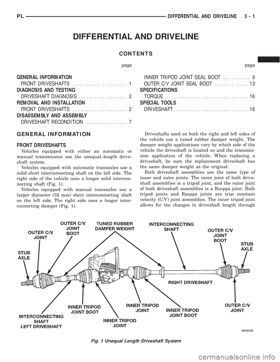
Vehicles equipped with automatic transaxles use a
solid short interconnecting shaft on the left side. The
right side of the vehicle uses a longer solid intercon-
necting shaft (Fig. 1).
Vehicles equipped with manual transaxles use a
larger diameter (32 mm) short interconnecting shaft
on the left side. The right side uses a longer inter-
connecting damper (Fig. 1).Driveshafts used on both the right and left sides of
the vehicle use a tuned rubber damper weight. The
damper weight applications vary by which side of the
vehicle the driveshaft is located on and the transmis-
sion application of the vehicle. When replacing a
driveshaft, be sure the replacement driveshaft has
the same damper weight as the original.
Both driveshaft assemblies use the same type of
inner and outer joints. The inner joint of both drive-
shaft assemblies is a tripod joint, and the outer joint
of both driveshaft assemblies is a Rzeppa joint. Both
tripod joints and Rzeppa joints are true constant
velocity (C/V) joint assemblies. The inner tripod joint
allows for the changes in driveshaft length through
Fig. 1 Unequal Length Driveshaft System
PLDIFFERENTIAL AND DRIVELINE 3 - 1
Page 82 of 1200
BRAKES
CONTENTS
page page
ANTILOCK BRAKE SYSTEM±TEVES MARK 20 . 69
BASE BRAKE SYSTEM..................... 2GENERAL INFORMATION................... 1
GENERAL INFORMATION
INDEX
page
GENERAL INFORMATION
BASE BRAKE SYSTEM DESCRIPTION........ 1
GENERAL INFORMATION
BASE BRAKE SYSTEM DESCRIPTION
Typical brake equipment consists of:
²Double pin floating caliper disc front brakes.
²Rear automatic adjusting drum brakes.
²Brake Fluid Level Switch.
²Master cylinder.
²Vacuum power booster.
²Double pin floating caliper rear disc brakes are
available on some models.
²Hand operated auto adjust park brake lever.
²Front disc brake pads are semi-metallic.
Vehicles equipped with the optional antilock brake
system (ABS) use a system designated Mark 20 and
is supplied by Teves. This system shares the base
brake hardware with vehicles not equipped withABS. A vehicle equipped with ABS does however use
a different vacuum booster, master cylinder and
brake tubes. Also included in the ABS system is an
integrated control unit (ICU), four wheel speed sen-
sors, and an electronic controller referred to as the
controller antilock brakes (CAB). These components
will be described in detail in the Teves Mark 20 ABS
brake section in this group of the service manual.
The hydraulic brake system is diagonally split on
both the Non-ABS and ABS braking system. With the
left front and right rear brakes on one hydraulic sys-
tem and the right front and left rear on the other.
The master cylinder is anodized, lightweight alu-
minum. On vehicles equipped with front disc brakes
and rear drum brakes, the master cylinder bore is
21.0 mm. On vehicles equipped with four wheel disc
brakes, the master cylinder bore is 22.2 mm.
PLBRAKES 5 - 1
Page 108 of 1200
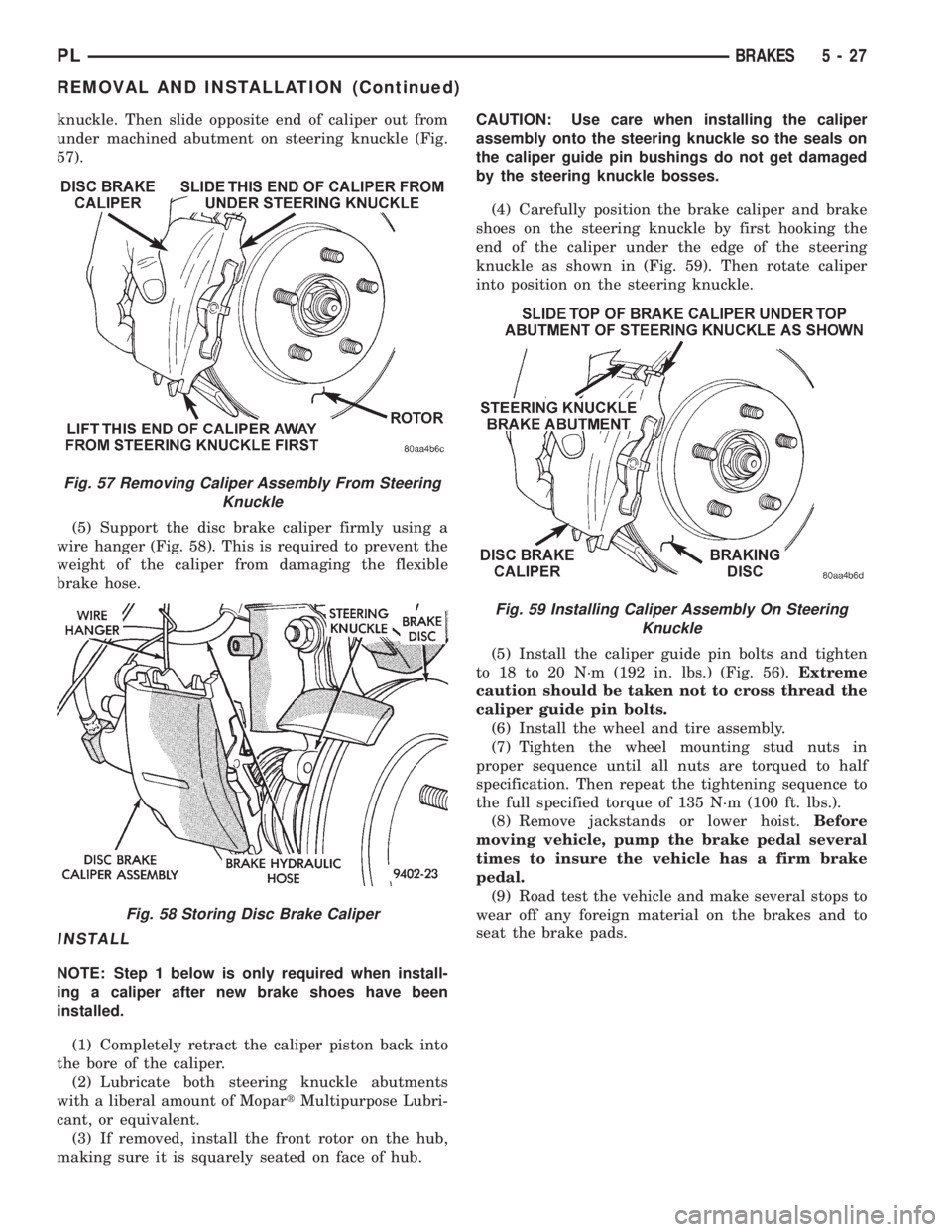
knuckle. Then slide opposite end of caliper out from
under machined abutment on steering knuckle (Fig.
57).
(5) Support the disc brake caliper firmly using a
wire hanger (Fig. 58). This is required to prevent the
weight of the caliper from damaging the flexible
brake hose.
INSTALL
NOTE: Step 1 below is only required when install-
ing a caliper after new brake shoes have been
installed.
(1) Completely retract the caliper piston back into
the bore of the caliper.
(2) Lubricate both steering knuckle abutments
with a liberal amount of MopartMultipurpose Lubri-
cant, or equivalent.
(3) If removed, install the front rotor on the hub,
making sure it is squarely seated on face of hub.CAUTION: Use care when installing the caliper
assembly onto the steering knuckle so the seals on
the caliper guide pin bushings do not get damaged
by the steering knuckle bosses.
(4) Carefully position the brake caliper and brake
shoes on the steering knuckle by first hooking the
end of the caliper under the edge of the steering
knuckle as shown in (Fig. 59). Then rotate caliper
into position on the steering knuckle.
(5) Install the caliper guide pin bolts and tighten
to 18 to 20 N´m (192 in. lbs.) (Fig. 56).Extreme
caution should be taken not to cross thread the
caliper guide pin bolts.
(6) Install the wheel and tire assembly.
(7) Tighten the wheel mounting stud nuts in
proper sequence until all nuts are torqued to half
specification. Then repeat the tightening sequence to
the full specified torque of 135 N´m (100 ft. lbs.).
(8) Remove jackstands or lower hoist.Before
moving vehicle, pump the brake pedal several
times to insure the vehicle has a firm brake
pedal.
(9) Road test the vehicle and make several stops to
wear off any foreign material on the brakes and to
seat the brake pads.
Fig. 57 Removing Caliper Assembly From Steering
Knuckle
Fig. 58 Storing Disc Brake Caliper
Fig. 59 Installing Caliper Assembly On Steering
Knuckle
PLBRAKES 5 - 27
REMOVAL AND INSTALLATION (Continued)
Page 109 of 1200
FRONT DISC BRAKE SHOES
WARNING: ALTHOUGH FACTORY INSTALLED
BRAKELININGS ARE MADE FROM ASBESTOS
FREE MATERIALS, SOME AFTER MARKET BRAKE-
LINING MAY CONTAIN ASBESTOS. THIS SHOULD
BE TAKEN INTO ACCOUNT WHEN SERVICING A
VEHICLE'S BRAKE SYSTEM, WHEN AFTERMARKET
BRAKELININGS MAY HAVE BEEN INSTALLED ON
THE VEHICLE. ALWAYS WEAR A RESPIRATOR
WHEN CLEANING BRAKE COMPONENTS AS
ASBESTOS CAN CAUSE SERIOUS BODILY HARM
SUCH AS ASBESTOSIS AND OR CANCER. NEVER
CLEAN BRAKE COMPONENTS BY USING COM-
PRESSED AIR, USE ONLY A VACUUM CLEANER
SPECIFICALLY DESIGNED FOR THE REMOVAL OF
BRAKE DUST. IF A VACUUM CLEANER IS NOT
AVAILABLE, CLEAN BRAKE PARTS USING ONLY
WATER DAMPENED SHOP TOWELS. DO NOT CRE-
ATE BRAKELINING DUST BY SANDING BRAKE LIN-
INGS WHEN SERVICING A VEHICLE. DISPOSE OF
ALL DUST AND DIRT SUSPECTED OF CONTAINING
ASBESTOS FIBERS USING ONLY SEALED AIR-
TIGHT BAGS OR CONTAINERS. FOLLOW ALL REC-
OMMENDED SAFETY PRACTICES PRESCRIBED BY
THE OCCUPATIONAL SAFETY AND HEALTH ADMIN-
ISTRATION (OSHA) AND THE ENVIRONMENTAL
PROTECTION AGENCY (EPA), FOR HANDLING AND
DISPOSAL OF PRODUCTS CONTAINING ASBES-
TOS.
During service procedures, grease or any other for-
eign material must be kept off caliper assembly, sur-
faces of braking rotor and external surfaces of hub.
Handling of the brake rotor and caliper should be
done in such a way as to avoid deformation of the
rotor and scratching or nicking of the brake linings.
If inspection reveals that the square sectioned cal-
iper piston seal is worn or damaged, it should be
replaced immediately.
During removal and installation of a wheel and
tire, use care not to strike the caliper.
NOTE: Before vehicle is moved after any brake
service work, pump the brake pedal several times
to insure the vehicle has a firm brake pedal.
NOTE: Starting with the 1998 model year, different
lining material is used on the disc brake shoes
depending on the type of brake system the vehicle
is equipped with. Vehicles equipped with standard
front disc and rear drum brakes use a new lining
material on the front disc brake shoes. Vehicles that
are equipped with optional 4 wheel disc brakes use
a new lining material on both the front and rear disc
brake shoes. When new brake shoes are installed,be sure brake shoes for the correct model year and
type of brake system the vehicle is equipped with
are used.
REMOVE
(1) Raise vehicle on jackstands or centered on a
hoist. See Hoisting in the Lubrication and Mainte-
nance section of this manual.
(2) Remove the front wheel and tire assemblies
from vehicle.
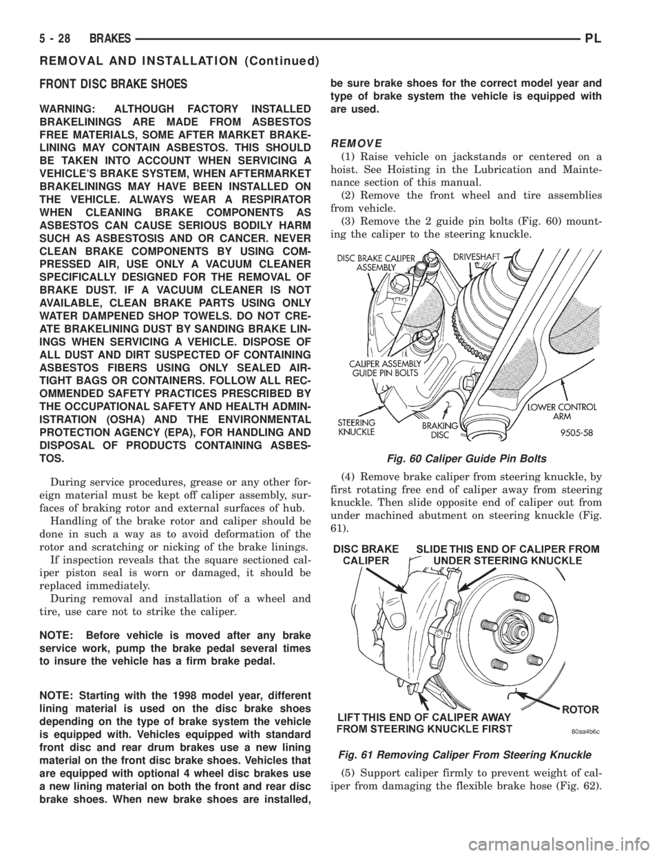
(3) Remove the 2 guide pin bolts (Fig. 60) mount-
ing the caliper to the steering knuckle.
(4) Remove brake caliper from steering knuckle, by
first rotating free end of caliper away from steering
knuckle. Then slide opposite end of caliper out from
under machined abutment on steering knuckle (Fig.
61).
(5) Support caliper firmly to prevent weight of cal-
iper from damaging the flexible brake hose (Fig. 62).
Fig. 60 Caliper Guide Pin Bolts
Fig. 61 Removing Caliper From Steering Knuckle
5 - 28 BRAKESPL
REMOVAL AND INSTALLATION (Continued)