1999 DODGE NEON differential
[x] Cancel search: differentialPage 1042 of 1200
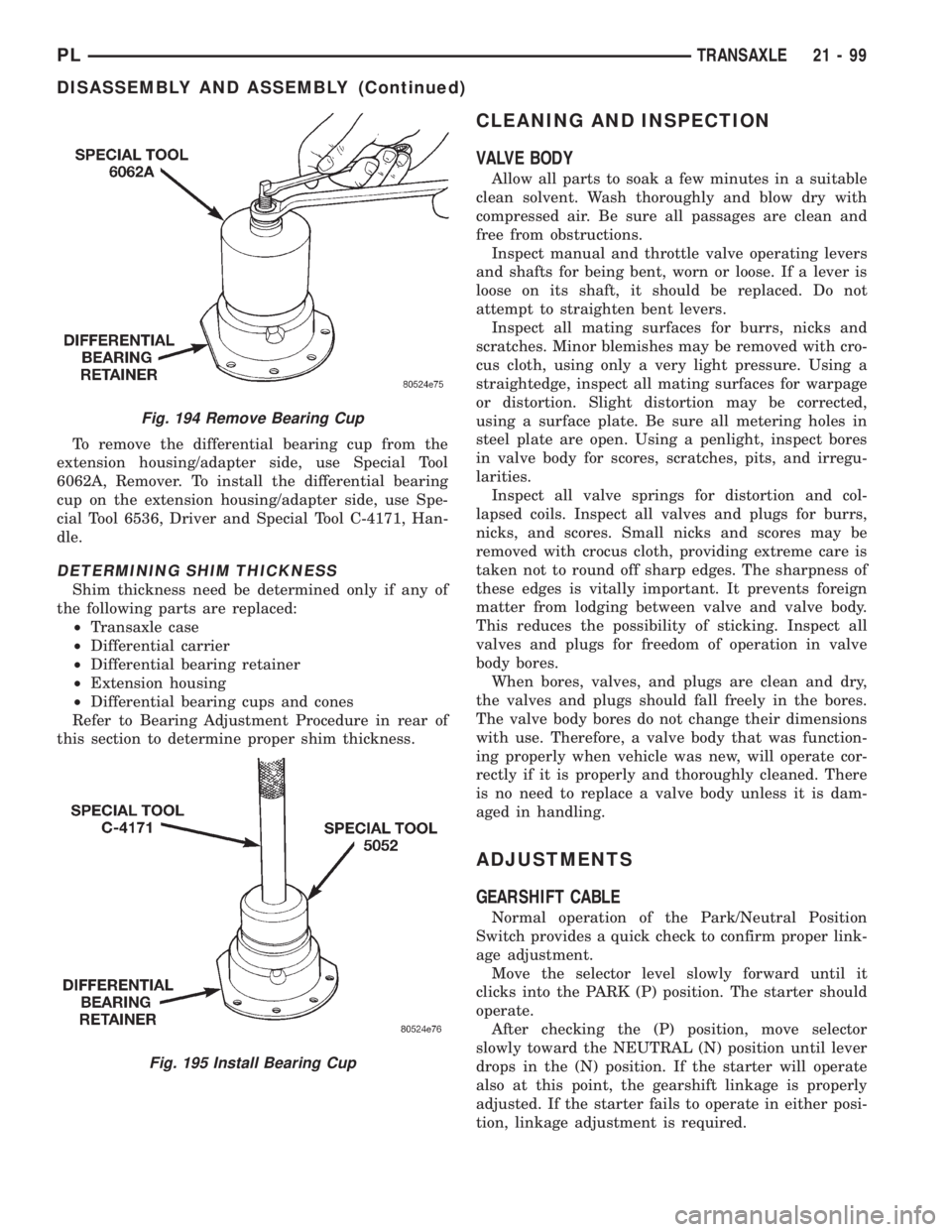
To remove the differential bearing cup from the
extension housing/adapter side, use Special Tool
6062A, Remover. To install the differential bearing
cup on the extension housing/adapter side, use Spe-
cial Tool 6536, Driver and Special Tool C-4171, Han-
dle.
DETERMINING SHIM THICKNESS
Shim thickness need be determined only if any of
the following parts are replaced:
²Transaxle case
²Differential carrier
²Differential bearing retainer
²Extension housing
²Differential bearing cups and cones
Refer to Bearing Adjustment Procedure in rear of
this section to determine proper shim thickness.
CLEANING AND INSPECTION
VALVE BODY
Allow all parts to soak a few minutes in a suitable
clean solvent. Wash thoroughly and blow dry with
compressed air. Be sure all passages are clean and
free from obstructions.
Inspect manual and throttle valve operating levers
and shafts for being bent, worn or loose. If a lever is
loose on its shaft, it should be replaced. Do not
attempt to straighten bent levers.
Inspect all mating surfaces for burrs, nicks and
scratches. Minor blemishes may be removed with cro-
cus cloth, using only a very light pressure. Using a
straightedge, inspect all mating surfaces for warpage
or distortion. Slight distortion may be corrected,
using a surface plate. Be sure all metering holes in
steel plate are open. Using a penlight, inspect bores
in valve body for scores, scratches, pits, and irregu-
larities.
Inspect all valve springs for distortion and col-
lapsed coils. Inspect all valves and plugs for burrs,
nicks, and scores. Small nicks and scores may be
removed with crocus cloth, providing extreme care is
taken not to round off sharp edges. The sharpness of
these edges is vitally important. It prevents foreign
matter from lodging between valve and valve body.
This reduces the possibility of sticking. Inspect all
valves and plugs for freedom of operation in valve
body bores.
When bores, valves, and plugs are clean and dry,
the valves and plugs should fall freely in the bores.
The valve body bores do not change their dimensions
with use. Therefore, a valve body that was function-
ing properly when vehicle was new, will operate cor-
rectly if it is properly and thoroughly cleaned. There
is no need to replace a valve body unless it is dam-
aged in handling.
ADJUSTMENTS
GEARSHIFT CABLE
Normal operation of the Park/Neutral Position
Switch provides a quick check to confirm proper link-
age adjustment.
Move the selector level slowly forward until it
clicks into the PARK (P) position. The starter should
operate.
After checking the (P) position, move selector
slowly toward the NEUTRAL (N) position until lever
drops in the (N) position. If the starter will operate
also at this point, the gearshift linkage is properly
adjusted. If the starter fails to operate in either posi-
tion, linkage adjustment is required.
Fig. 194 Remove Bearing Cup
Fig. 195 Install Bearing Cup
PLTRANSAXLE 21 - 99
DISASSEMBLY AND ASSEMBLY (Continued)
Page 1045 of 1200
(4) Used (original) bearing may lose up to 50 per-
cent of the original drag torque after break-in.
NOTE: All bearing adjustments must be made with
no other component interference or gear inter-
mesh, except the transfer gear bearing.
(5) Refer to the conversion chart in specifications
to convert inches to millimeter measurements. Refer
to bearing shim chart for proper shim thicknesses.
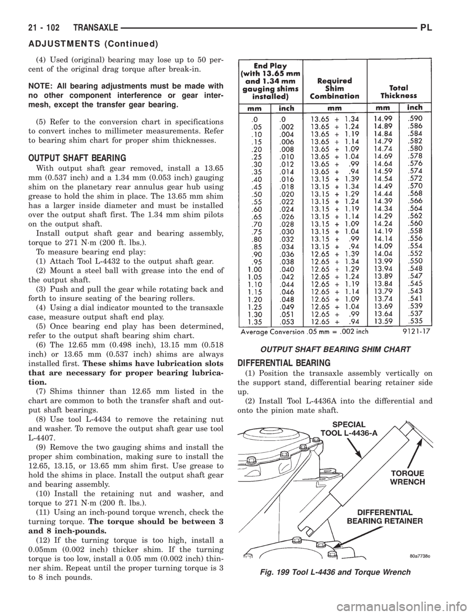
OUTPUT SHAFT BEARING
With output shaft gear removed, install a 13.65
mm (0.537 inch) and a 1.34 mm (0.053 inch) gauging
shim on the planetary rear annulus gear hub using
grease to hold the shim in place. The 13.65 mm shim
has a larger inside diameter and must be installed
over the output shaft first. The 1.34 mm shim pilots
on the output shaft.
Install output shaft gear and bearing assembly,
torque to 271 N´m (200 ft. lbs.).
To measure bearing end play:
(1) Attach Tool L-4432 to the output shaft gear.
(2) Mount a steel ball with grease into the end of
the output shaft.
(3) Push and pull the gear while rotating back and
forth to insure seating of the bearing rollers.
(4) Using a dial indicator mounted to the transaxle
case, measure output shaft end play.
(5) Once bearing end play has been determined,
refer to the output shaft bearing shim chart.
(6) The 12.65 mm (0.498 inch), 13.15 mm (0.518
inch) or 13.65 mm (0.537 inch) shims are always
installed first.These shims have lubrication slots
that are necessary for proper bearing lubrica-
tion.
(7) Shims thinner than 12.65 mm listed in the
chart are common to both the transfer shaft and out-
put shaft bearings.
(8) Use tool L-4434 to remove the retaining nut
and washer. To remove the output shaft gear use tool
L-4407.
(9) Remove the two gauging shims and install the
proper shim combination, making sure to install the
12.65, 13.15, or 13.65 mm shim first. Use grease to
hold the shims in place. Install the output shaft gear
and bearing assembly.
(10) Install the retaining nut and washer, and
torque to 271 N´m (200 ft. lbs.).
(11) Using an inch-pound torque wrench, check the
turning torque.The torque should be between 3
and 8 inch-pounds.
(12) If the turning torque is too high, install a
0.05mm (0.002 inch) thicker shim. If the turning
torque is too low, install a 0.05 mm (0.002 inch) thin-
ner shim. Repeat until the proper turning torque is 3
to 8 inch pounds.
DIFFERENTIAL BEARING
(1) Position the transaxle assembly vertically on
the support stand, differential bearing retainer side
up.
(2) Install Tool L-4436A into the differential and
onto the pinion mate shaft.
OUTPUT SHAFT BEARING SHIM CHART
Fig. 199 Tool L-4436 and Torque Wrench
21 - 102 TRANSAXLEPL
ADJUSTMENTS (Continued)
Page 1046 of 1200
(3) Rotate the differential at least one full revolu-
tion to ensure the tapered roller bearings are fully
seated.
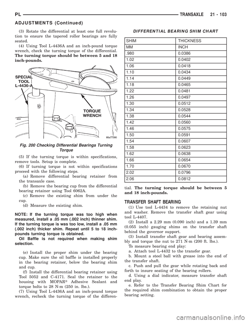
(4) Using Tool L-4436A and an inch-pound torque
wrench, check the turning torque of the differential.
The turning torque should be between 5 and 18
inch-pounds.
(5) If the turning torque is within specifications,
remove tools. Setup is complete.
(6) If turning torque is not within specifications
proceed with the following steps.
(a) Remove differential bearing retainer from
the transaxle case.
(b) Remove the bearing cup from the differential
bearing retainer using Tool 6062A.
(c) Remove the existing shim from under the
cup.
(d) Measure the existing shim.
NOTE: If the turning torque was too high when
measured, install a .05 mm (.002 inch) thinner shim.
If the turning torque is was too low, install a .05 mm
(.002 inch) thicker shim. Repeat until 5 to 18 inch-
pounds turning torque is obtained.
Oil Baffle is not required when making shim
selection.
(e) Install the proper shim under the bearing
cup. Make sure the oil baffle is installed properly
in the bearing retainer, below the bearing shim
and cup.
(f) Install the differential bearing retainer using
Tool 5052 and C-4171. Seal the retainer to the
housing with MOPARtAdhesive Sealant and
torque bolts to 28 N´m (250 in. lbs.).
(7) Using Tool L-4436A and an inch-pound torque
wrench, recheck the turning torque of the differen-tial.The turning torque should be between 5
and 18 inch-pounds.
TRANSFER SHAFT BEARING
(1) Use tool L-4434 to remove the retaining nut
and washer. Remove the transfer shaft gear using
tool L-4407.
(2) Install a 2.29 mm (0.090 inch) and a 1.39 mm
(0.055 inch) gauging shims on the transfer shaft
behind the governor support.
(3) Install transfer shaft gear and bearing assem-
bly and torque the nut to 271 N´m (200 ft. lbs.).
To measure bearing end play:
a. Attach tool L-4432 to the transfer gear.
b. Mount a steel ball with grease into the end of
the transfer shaft.
c. Push and pull the gear while rotating back and
forth to insure seating of the bearing rollers.
d. Using a dial indicator, measure transfer shaft
end play.
e. Refer to the Transfer Bearing Shim Chart for
the required shim combination to obtain the proper
bearing setting.
Fig. 200 Checking Differential Bearings Turning
Torque
DIFFERENTIAL BEARING SHIM CHART
SHIM THICKNESS
MM INCH
.980 0.0386
1.02 0.0402
1.06 0.0418
1.10 0.0434
1.14 0.0449
1.18 0.0465
1.22 0.0481
1.26 0.0497
1.30 0.0512
1.34 0.0528
1.38 0.0544
1.42 0.0560
1.46 0.0575
1.50 0.0591
1.54 0.0607
1.58 0.0623
1.62 0.0638
1.66 0.0654
1.70 0.0670
2.02 0.0796
2.06 0.0812
PLTRANSAXLE 21 - 103
ADJUSTMENTS (Continued)
Page 1056 of 1200
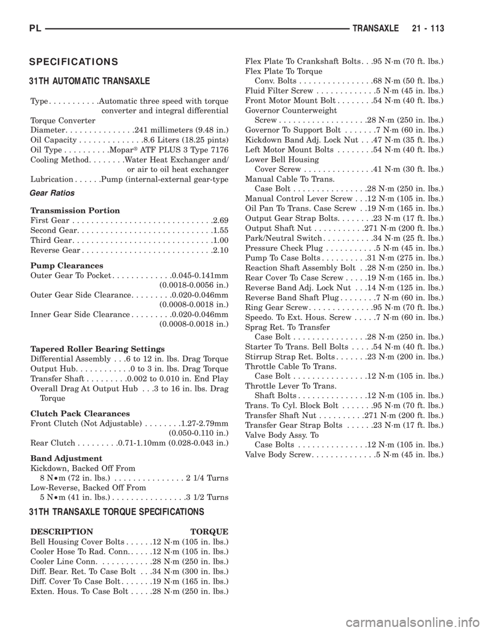
SPECIFICATIONS
31TH AUTOMATIC TRANSAXLE
Type...........Automatic three speed with torque
converter and integral differential
Torque Converter
Diameter...............241 millimeters (9.48 in.)
Oil Capacity..............8.6 Liters (18.25 pints)
OilType..........MopartATF PLUS 3 Type 7176
Cooling Method........Water Heat Exchanger and/
or air to oil heat exchanger
Lubrication......Pump (internal-external gear-type
Gear Ratios
Transmission Portion
First Gear..............................2.69
Second Gear.............................1.55
Third Gear..............................1.00
Reverse Gear............................2.10
Pump Clearances
Outer Gear To Pocket.............0.045-0.141mm
(0.0018-0.0056 in.)
Outer Gear Side Clearance.........0.020-0.046mm
(0.0008-0.0018 in.)
Inner Gear Side Clearance.........0.020-0.046mm
(0.0008-0.0018 in.)
Tapered Roller Bearing Settings
Differential Assembly . . .6 to 12 in. lbs. Drag Torque
Output Hub............0to3in.lbs. Drag Torque
Transfer Shaft.........0.002 to 0.010 in. End Play
Overall Drag At Output Hub . . .3 to 16 in. lbs. Drag
Torque
Clutch Pack Clearances
Front Clutch (Not Adjustable)........1.27-2.79mm
(0.050-0.110 in.)
Rear Clutch.........0.71-1.10mm (0.028-0.043 in.)
Band Adjustment
Kickdown, Backed Off From
8N²m (72 in. lbs.)...............21/4Turns
Low-Reverse, Backed Off From
5N²m (41 in. lbs.)................31/2Turns
31TH TRANSAXLE TORQUE SPECIFICATIONS
DESCRIPTION TORQUE
Bell Housing Cover Bolts......12N´m(105 in. lbs.)
Cooler Hose To Rad. Conn......12N´m(105 in. lbs.)
Cooler Line Conn............28N´m(250 in. lbs.)
Diff. Bear. Ret. To Case Bolt . . .34 N´m (300 in. lbs.)
Diff. Cover To Case Bolt.......19N´m(165 in. lbs.)
Exten. Hous. To Case Bolt.....28N´m(250 in. lbs.)Flex Plate To Crankshaft Bolts . . .95 N´m (70 ft. lbs.)
Flex Plate To Torque
Conv. Bolts................68N´m(50ft.lbs.)
Fluid Filter Screw.............5N´m(45in.lbs.)
Front Motor Mount Bolt........54N´m(40ft.lbs.)
Governor Counterweight
Screw...................28N´m(250 in. lbs.)
Governor To Support Bolt.......7N´m(60in.lbs.)
Kickdown Band Adj. Lock Nut . . .47 N´m (35 ft. lbs.)
Left Motor Mount Bolts........54N´m(40ft.lbs.)
Lower Bell Housing
Cover Screw...............41N´m(30ft.lbs.)
Manual Cable To Trans.
Case Bolt................28N´m(250 in. lbs.)
Manual Control Lever Screw . . .12 N´m (105 in. lbs.)
Oil Pan To Trans. Case Screw . .19 N´m (165 in. lbs.)
Output Gear Strap Bolts........23N´m(17ft.lbs.)
Output Shaft Nut...........271 N´m (200 ft. lbs.)
Park/Neutral Switch...........34N´m(25ft.lbs.)
Pressure Check Plug...........5N´m(45in.lbs.)
Pump To Case Bolts..........31N´m(275 in. lbs.)
Reaction Shaft Assembly Bolt . .28 N´m (250 in. lbs.)
Rear Cover To Case Screw.....19N´m(165 in. lbs.)
Reverse Band Adj. Lock Nut . . .14 N´m (125 in. lbs.)
Reverse Band Shaft Plug........7N´m(60in.lbs.)
Ring Gear Screw..............95N´m(70ft.lbs.)
Speedo. To Ext. Hous. Screw.....7N´m(60in.lbs.)
Sprag Ret. To Transfer
Case Bolt................28N´m(250 in. lbs.)
Starter To Trans. Bell Bolts.....54N´m(40ft.lbs.)
Stirrup Strap Ret. Bolts.......23N´m(200 in. lbs.)
Throttle Cable To Trans.
Case Bolt................12N´m(105 in. lbs.)
Throttle Lever To Trans.
Shaft Bolts...............12N´m(105 in. lbs.)
Trans. To Cyl. Block Bolt.......95N´m(70ft.lbs.)
Transfer Shaft Nut..........271 N´m (200 ft. lbs.)
Transfer Gear Strap Bolts......23N´m(17ft.lbs.)
Valve Body Assy. To
Case Bolts...............12N´m(105 in. lbs.)
Valve Body Screw..............5N´m(45in.lbs.)
PLTRANSAXLE 21 - 113
Page 1060 of 1200
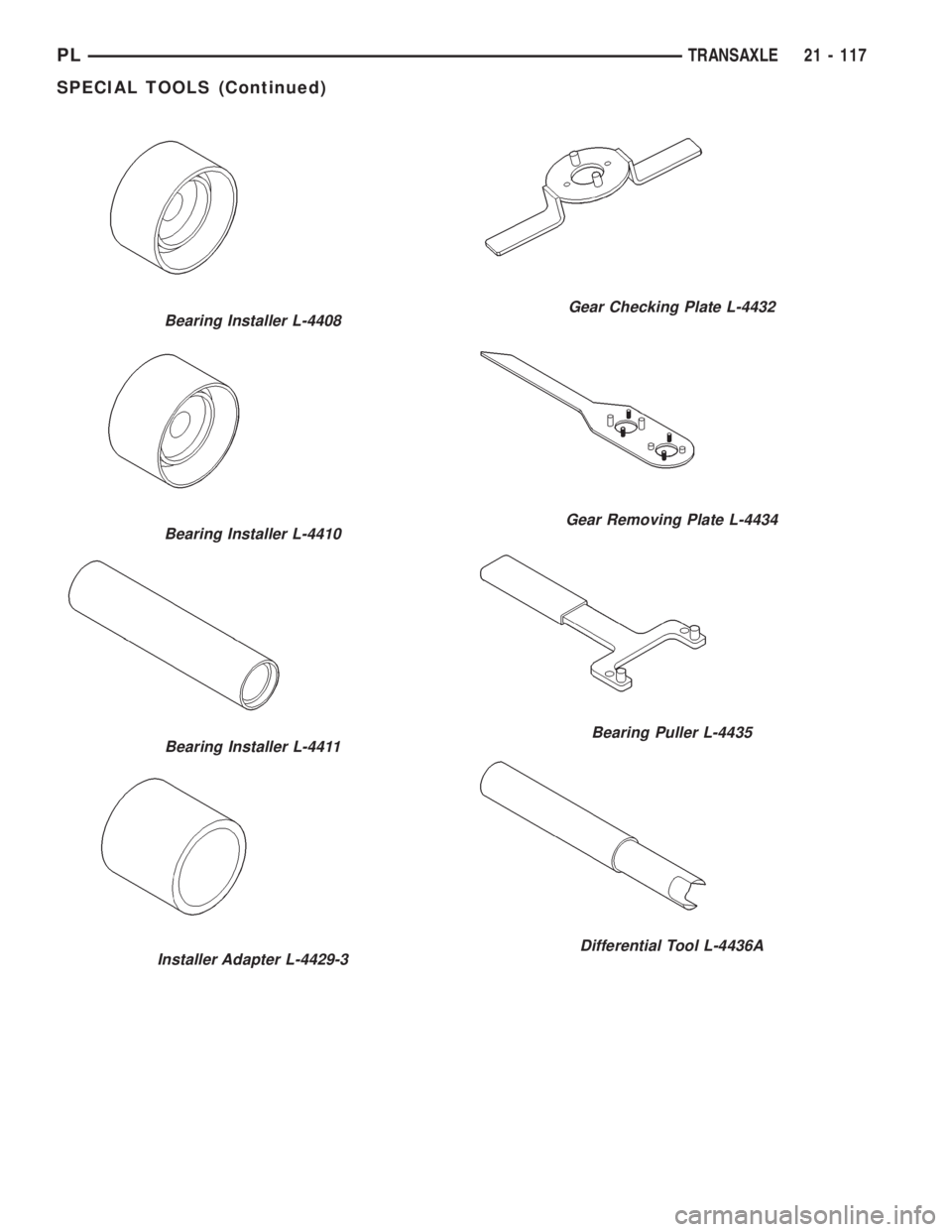
Bearing Installer L-4408
Bearing Installer L-4410
Bearing Installer L-4411
Installer Adapter L-4429-3
Gear Checking Plate L-4432
Gear Removing Plate L-4434
Bearing Puller L-4435
Differential Tool L-4436A
PLTRANSAXLE 21 - 117
SPECIAL TOOLS (Continued)
Page 1071 of 1200
TIRE NOISE OR VIBRATION
Radial-ply tires are sensitive to force impulses
caused by improper mounting, vibration, wheel
defects, or possibly tire imbalance.
To find out if tires are causing the noise or vibra-
tion, drive the vehicle over a smooth road at varying
speeds. Note the noise level during acceleration and
deceleration. The engine, differential and exhaust
noises will change as speed varies, while the tire
noise will usually remain constant.
LEAD CORRECTION CHART
Use the following chart to diagnose a vehicle that
has a complaint of a drift or lead condition. The use
of the chart will help to determine if the lead condi-
tion is the result of a bad tire or is caused by the
front wheel alignment.
SERVICE PROCEDURES
TIRE AND WHEEL ROTATION
NON-DIRECTIONAL TREAD PATTERN TIRES
Tires on the front and rear axles operate at differ-
ent loads and perform different functions. For these
reasons, they wear at unequal rates, and tend to
develop irregular wear patterns. These effects can be
reduced by timely rotation of tires. The benefits of
rotation are especially worthwhile. Rotation will
increase tread life, help to maintain mud, snow, and
wet traction levels, and contribute to a smooth, quiet
ride.
The suggested rotation method is the forward-cross
tire rotation method (Fig. 6). This method takes
advantage of current tire industry practice whichallows rotation of radial-ply tires. Other rotation
methods may be used, but may not have all the ben-
efits of the recommended method.
NOTE: Only the 4 tire rotation method may be used
if the vehicle is equipped with a low mileage or tem-
porary spare tire.
DIRECTIONAL TREAD PATTERN TIRES
Some vehicles are fitted with special high-perfor-
mance tires having a directional tread pattern. These
tires are designed to improve traction on wet pave-
ment. To obtain the full benefits of this design, the
tires must be installed so that they rotate in the cor-
rect direction. This is indicated by arrows on the tire
sidewalls.
When wheels and tires are being installed, extra
care is needed to ensure that this direction of rota-
tion is maintained.
Refer to Owner's Manual for rotation schedule.
REPAIRING TIRE LEAKS
For proper repairing, a radial tire must be removed
from the wheel. Repairs should only be made if the
defect, or puncture, is in the tread area (Fig. 7). The
tire should be replaced if the puncture is located in
the sidewall.
Deflate tire completely before attempting to dis-
mount the tire from the wheel.Use a lubricant
such as a mild soap solution when dismounting
or mounting tire.Use tools free of burrs or sharp
edges which could damage the tire or wheel rim.
Before mounting tire on wheel, make sure all rust
is removed from the rim bead and repaint if neces-
sary.
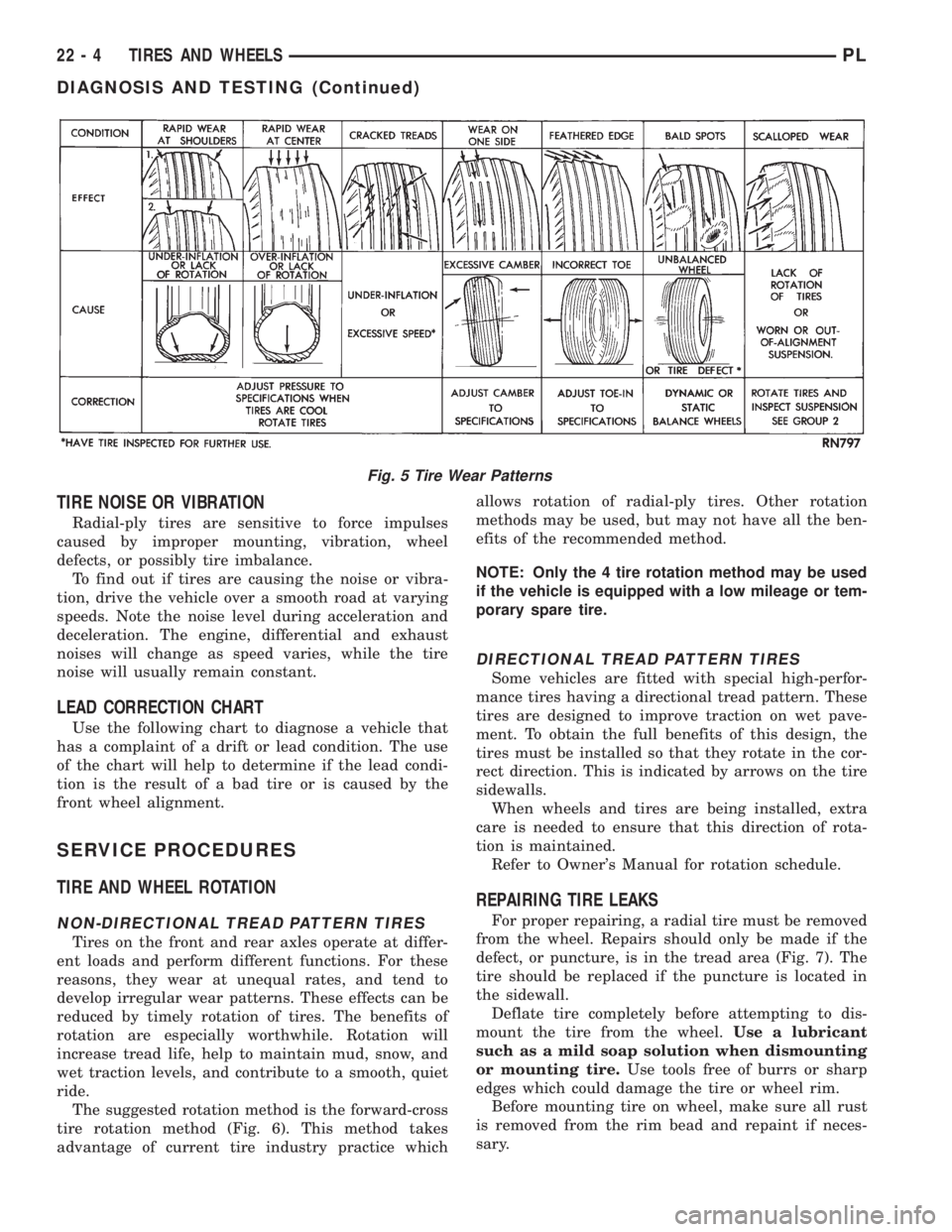
Fig. 5 Tire Wear Patterns
22 - 4 TIRES AND WHEELSPL
DIAGNOSIS AND TESTING (Continued)
Page 1200 of 1200
GROUP TAB LOCATOR
INIntroduction
INaIntroduction
0Lubrication and Maintenance
2Suspension
3Differential and Driveline
5Brakes
6Clutch
6aClutch
7Cooling
8ABattery
8BStarting
8CCharging System
8CaCharging System
8DIgnition System
8EInstrument Panel and Systems
8EaInstrument Panel and Systems
8FAudio System
8GHorns
8HVehicle Speed Control System
8HaVehicle Speed Control System
8JTurn Signal and Flashers
8KWindshield Wipers and Washers
8KaWindshield Wipers and Washers
8LLamps
8LaLamps
8MRestraint System
8NElectrically Heated Systems
8NaElectrically Heated Systems
8PPower Door Locks
8QaImmobilizer System
8SPower Windows
8TPower Mirrors
8TaPower Mirrors
8UChime Warning/Reminder System
8WWiring Diagrams - LHD and RHD
9Engine
9aEngine
11Exhaust System and Intake Manifold
11aExhaust System and Intake Manifold
13Frame and Bumpers
13aFrame and Bumpers
14Fuel System
14aFuel System - 1.8L Engine
19Steering
19aSteering
21Transaxle
21aTransaxle
22Tires and Wheels
23Body
24Heating and Air Conditioning
25Emission Control Systems
25aEmission Control System - 1.8L Engine