Page 968 of 1200
correct bearing preload and proper bearing turning
torque.
DIFFERENTIAL BEARINGS
RING GEAR
Fig. 95 Remove Differential Bearing Cone
Fig. 96 Install Differential Bearing Cone
Fig. 97 Remove Differential Bearing Cone
Fig. 98 Install Differential Bearing Cone
Fig. 99 Remove or Install Ring Gear Bolts and Ring
Gear
PLTRANSAXLE 21 - 25
DISASSEMBLY AND ASSEMBLY (Continued)
Page 969 of 1200
CAUTION: Always install new ring gear bolts.
Tighten ring gear bolts to 81 N´m (60 ft. lbs.) torque.
SPEEDOMETER DRIVE GEAR
NOTE: The plastic speedometer drive gear must be
removed from the differential case in order to ser-
vice the differential gears
REMOVAL
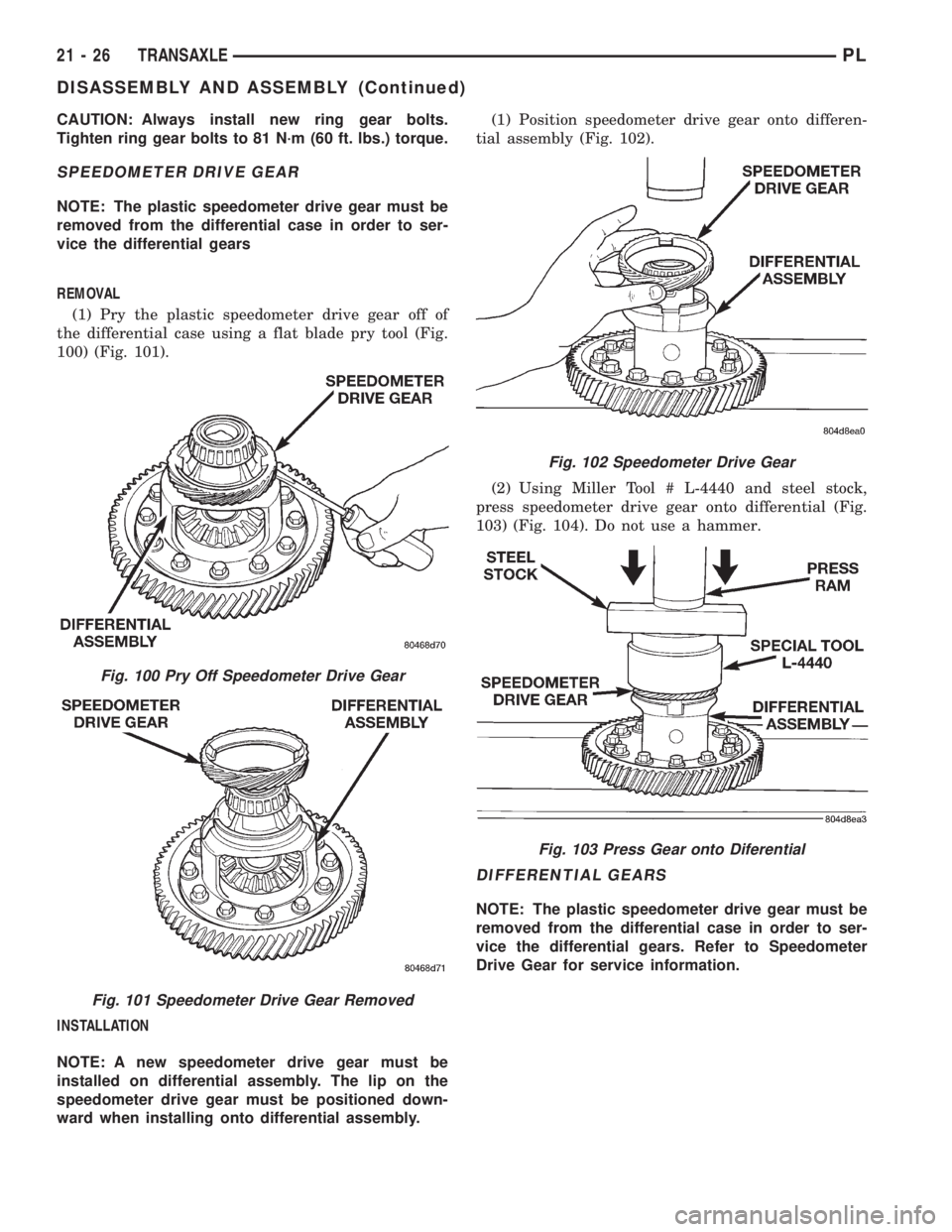
(1) Pry the plastic speedometer drive gear off of
the differential case using a flat blade pry tool (Fig.
100) (Fig. 101).
INSTALLATION
NOTE: A new speedometer drive gear must be
installed on differential assembly. The lip on the
speedometer drive gear must be positioned down-
ward when installing onto differential assembly.(1) Position speedometer drive gear onto differen-
tial assembly (Fig. 102).
(2) Using Miller Tool # L-4440 and steel stock,
press speedometer drive gear onto differential (Fig.
103) (Fig. 104). Do not use a hammer.
DIFFERENTIAL GEARS
NOTE: The plastic speedometer drive gear must be
removed from the differential case in order to ser-
vice the differential gears. Refer to Speedometer
Drive Gear for service information.
Fig. 100 Pry Off Speedometer Drive Gear
Fig. 101 Speedometer Drive Gear Removed
Fig. 102 Speedometer Drive Gear
Fig. 103 Press Gear onto Diferential
21 - 26 TRANSAXLEPL
DISASSEMBLY AND ASSEMBLY (Continued)
Page 970 of 1200
REMOVAL
(1) Remove pinion shaft retaining pin (Fig. 105)
(Fig. 106).
(2) Remove pinion shaft (Fig. 107).(3) Rotate side gears to opening in differential
(Fig. 108).
(4) Remove differential gears (Fig. 109).
Fig. 104 Drive Gear Pressed onto Differential
Fig. 105 Remove Pinion Shaft Retaining Pin
Fig. 106 Retaining Pin Removed
Fig. 107 Pinion Shaft Removal
Fig. 108 Remove Pinion Gears, Side Gears, and
Thrust Washers by Rotating Side Gears to Opening
in Case
PLTRANSAXLE 21 - 27
DISASSEMBLY AND ASSEMBLY (Continued)
Page 971 of 1200
INSTALLATION
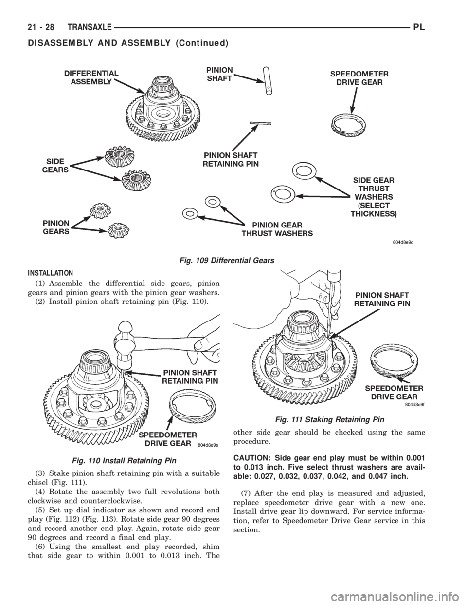
(1) Assemble the differential side gears, pinion
gears and pinion gears with the pinion gear washers.
(2) Install pinion shaft retaining pin (Fig. 110).
(3) Stake pinion shaft retaining pin with a suitable
chisel (Fig. 111).
(4) Rotate the assembly two full revolutions both
clockwise and counterclockwise.
(5) Set up dial indicator as shown and record end
play (Fig. 112) (Fig. 113). Rotate side gear 90 degrees
and record another end play. Again, rotate side gear
90 degrees and record a final end play.
(6) Using the smallest end play recorded, shim
that side gear to within 0.001 to 0.013 inch. Theother side gear should be checked using the same
procedure.
CAUTION: Side gear end play must be within 0.001
to 0.013 inch. Five select thrust washers are avail-
able: 0.027, 0.032, 0.037, 0.042, and 0.047 inch.
(7) After the end play is measured and adjusted,
replace speedometer drive gear with a new one.
Install drive gear lip downward. For service informa-
tion, refer to Speedometer Drive Gear service in this
section.
Fig. 109 Differential Gears
Fig. 110 Install Retaining Pin
Fig. 111 Staking Retaining Pin
21 - 28 TRANSAXLEPL
DISASSEMBLY AND ASSEMBLY (Continued)
Page 973 of 1200
Remove the shift lug roll pin and remove the shift
lug. Replace parts as necessary.
(3) To service the 3-4 shift rail, remove the roll pin
retaining the 3-4 shift fork. Remove the shift fork.
Remove the shift lug roll pin and remove the shift
lug. Replace parts as necessary.
(4) To service the 1-2 shift rail, remove the roll pin
retaining the 1-2 shift fork. Remove the shift fork
and replace parts as necessary.
TRANSAXLE CASE OVERHAUL
The sealant used to seal the transaxle case halves
is MopartGasket Maker, Loctitet518, or equivalent.
The sealant used for the bearing end±plate cover is
MopartRTV.
The components that are left in the gear cases
when the gear train is pulled out are the:
²Axle shaft seals
²Output bearing race and retainer
²Input bearing and sleeve
²Differential bearing cones
²Shift rail bushings
²Shift shafts
²Shift shaft seals
²Shift shaft bushings
²Rear bearing oil feed trough
AXLE SHAFT SEALS
REMOVAL
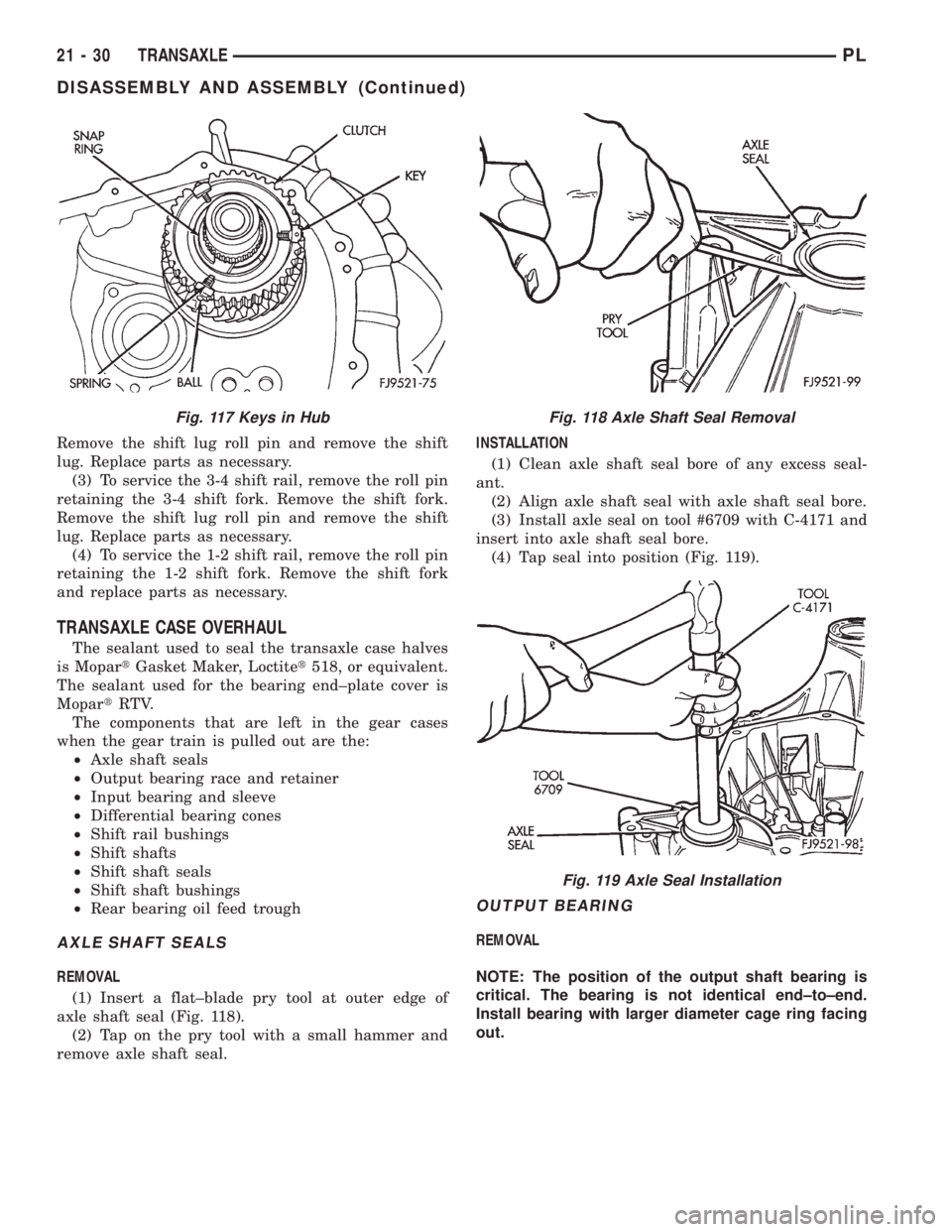
(1) Insert a flat±blade pry tool at outer edge of
axle shaft seal (Fig. 118).
(2) Tap on the pry tool with a small hammer and
remove axle shaft seal.INSTALLATION
(1) Clean axle shaft seal bore of any excess seal-
ant.
(2) Align axle shaft seal with axle shaft seal bore.
(3) Install axle seal on tool #6709 with C-4171 and
insert into axle shaft seal bore.
(4) Tap seal into position (Fig. 119).
OUTPUT BEARING
REMOVAL
NOTE: The position of the output shaft bearing is
critical. The bearing is not identical end±to±end.
Install bearing with larger diameter cage ring facing
out.
Fig. 117 Keys in HubFig. 118 Axle Shaft Seal Removal
Fig. 119 Axle Seal Installation
21 - 30 TRANSAXLEPL
DISASSEMBLY AND ASSEMBLY (Continued)
Page 975 of 1200
REMOVAL
(1) Install tool #6342 over input bearing on the
gear case side of the transaxle clutch housing.
(2) Press the input bearing out of the housing (Fig.
125).
INSTALLATION
(1) Apply coating of Loctitetsealant on bearing
outer diameter. Position sleeve and bearing assembly
at input bearing bore.
(2) Install tool #C-4680-1 over input bearing (Fig.
126).
(3) Using the spacer tool #4894 and shop press,
install input bearing into bore until it is fully seated
(Fig. 127).
DIFFERENTIAL BEARING CUPS
REMOVAL
(1) Remove differential assembly from gear case
using the procedure outlined in this group.(2) Install Miller tool #L-4518 into the differential
bearing cup (Fig. 128).
(3) Install the tool cup over the tool (Fig. 129).
Fig. 124 Input Bearing And Sleeve
Fig. 125 Input Bearing Removal
Fig. 126 Input Bearing Tool
Fig. 127 Input Bearing Installed
Fig. 128 Tool Installed in Bearing
21 - 32 TRANSAXLEPL
DISASSEMBLY AND ASSEMBLY (Continued)
Page 976 of 1200
(4) Tighten the tool until the race is removed from
the case.
INSTALLATION
(1) Position the bearing cup into the case.
(2) Install the bearing cup onto Miller tool
#L-4520.
(3) Using Miller tool #L-4520 and C-4171 driver,
install differential bearing cup into the transaxle
case.
SHIFT RAIL BUSHINGS
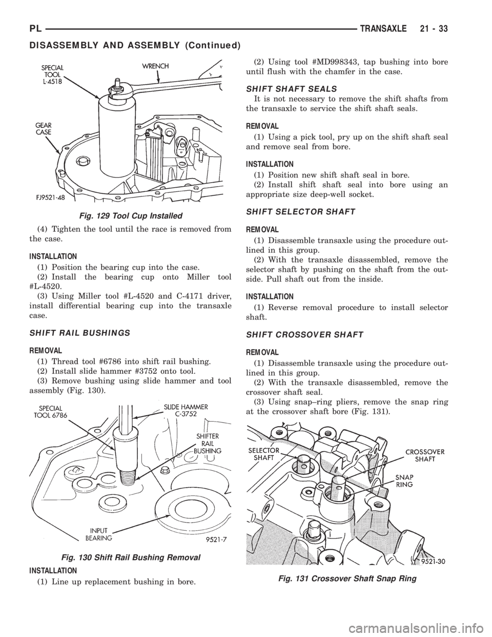
REMOVAL
(1) Thread tool #6786 into shift rail bushing.
(2) Install slide hammer #3752 onto tool.
(3) Remove bushing using slide hammer and tool
assembly (Fig. 130).
INSTALLATION
(1) Line up replacement bushing in bore.(2) Using tool #MD998343, tap bushing into bore
until flush with the chamfer in the case.
SHIFT SHAFT SEALS
It is not necessary to remove the shift shafts from
the transaxle to service the shift shaft seals.
REMOVAL
(1) Using a pick tool, pry up on the shift shaft seal
and remove seal from bore.
INSTALLATION
(1) Position new shift shaft seal in bore.
(2) Install shift shaft seal into bore using an
appropriate size deep-well socket.
SHIFT SELECTOR SHAFT
REMOVAL
(1) Disassemble transaxle using the procedure out-
lined in this group.
(2) With the transaxle disassembled, remove the
selector shaft by pushing on the shaft from the out-
side. Pull shaft out from the inside.
INSTALLATION
(1) Reverse removal procedure to install selector
shaft.
SHIFT CROSSOVER SHAFT
REMOVAL
(1) Disassemble transaxle using the procedure out-
lined in this group.
(2) With the transaxle disassembled, remove the
crossover shaft seal.
(3) Using snap±ring pliers, remove the snap ring
at the crossover shaft bore (Fig. 131).
Fig. 129 Tool Cup Installed
Fig. 130 Shift Rail Bushing Removal
Fig. 131 Crossover Shaft Snap Ring
PLTRANSAXLE 21 - 33
DISASSEMBLY AND ASSEMBLY (Continued)
Page 979 of 1200
for installation, as a hammer may not properly align
the bearing cup or cone. Burrs or nicks on the bear-
ing seat will give a false end play reading while
gauging for proper shims. Improperly seated bearing
cups and cones are subject to low±mileage failure.
(2) Bearing cups and cones should be replaced if
they show signs of pitting or heat distress. If distress
is seen on either the cup or bearing rollers, both cup
and cone must be replaced.
(3) Bearing preload and drag torque specifications
must be maintained to avoid premature bearing fail-
ures. Used (original) bearings may lose up to 50% of
their original drag torque after break in. All bearing
adjustments must be made with no other component
interference or gear intermesh.
(4) Replace bearings as a pair: If one differential
bearing is defective, replace both differential bear-
ings, if one input shaft bearing is defective, replace
both input shaft bearings.
(5) Bearing cones must not be reused if removed.
(6) Turning torque readings should be obtained
while smoothly rotating in either direction.
DIFFERENTIAL BEARING PRELOAD ADJUSTMENT
NOTE: True bearing turning torque readings can be
obtained only with the geartrain removed from the
case.
(1) Remove bearing cup and existing shim from
clutch bellhousing case.
(2) Press in new bearing cup into bellhousing case
(or use a cup that has been ground down on the
outer edge for ease of measurement).
(3) Press in new bearing cup into gear case side.
(4) Oil differential bearings with Moparttype M.S.
9417 Manual Transaxle Fluid. Install differential
assembly in transaxle gear case. Install clutch bell-
housing over gear case. Install and torque case bolts
to 29 N´m (21 ft. lbs.).
(5) Position transaxle with bellhousing facing
down on workbench with C-clamps. Position dial
indicator.
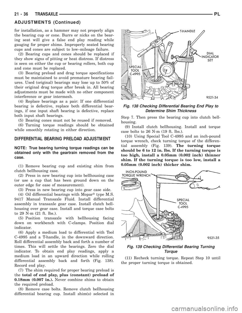
(6) Apply a medium load to differential with Tool
C-4995 and a T-handle, in the downward direction.
Roll differential assembly back and forth a number of
times. This will settle the bearings. Zero the dial
indicator. To obtain end play readings, apply a
medium load in an upward direction while rolling
differential assembly back and forth (Fig. 138).
Record end play.
(7) The shim required for proper bearing preload is
thetotal of end play, plus (constant) preload of
0.18mm (0.007 in.).Never combine shims to obtain
the required preload.
(8) Remove case bolts. Remove clutch bellhousing
differential bearing cup. Install shim(s) selected inStep 7. Then press the bearing cup into clutch bell-
housing.
(9) Install clutch bellhousing. Install and torque
case bolts to 26 N´m (19 ft. lbs.).
(10) Using Special Tool C-4995 and an inch-pound
torque wrench, check turning torque of the differen-
tial assembly (Fig. 139).The turning torque
should be 6 to 12 in. lbs. If the turning torque is
too high, install a 0.05mm (0.002 inch) thinner
shim. If the turning torque is too low, install a
0.05mm (0.002 inch) thicker shim.
(11) Recheck turning torque. Repeat Step 10 until
the proper turning torque is obtained.
Fig. 138 Checking Differential Bearing End Play to
Determine Shim Thickness
Fig. 139 Checking Differential Bearing Turning
Torque
21 - 36 TRANSAXLEPL
ADJUSTMENTS (Continued)