1999 DODGE NEON differential
[x] Cancel search: differentialPage 944 of 1200
TRANSAXLE
CONTENTS
page page
31TH AUTOMATIC TRANSAXLE............. 40 NVT350 (A-578) MANUAL TRANSAXLE....... 1
NV T350 (A-578) MANUAL TRANSAXLE
INDEX
page page
GENERAL INFORMATION
GEAR RATIOS........................... 2
GEARSHIFT PATTERN..................... 2
NV T350 MANUAL TRANSAXLE.............. 1
SEALANTS.............................. 2
SELECTION OF LUBRICANT................ 2
SPECIAL ADDITIVES...................... 2
TRANSAXLE IDENTIFICATION INFORMATION . . . 2
DESCRIPTION AND OPERATION
AXLE SEALS............................ 3
SHIFT LEVERS.......................... 3
DIAGNOSIS AND TESTING
CLUTCH PROBLEMS...................... 3
COMMON PROBLEM CAUSES.............. 3
HARD SHIFTING......................... 3
LOW LUBRICANT LEVEL................... 3
NOISY OPERATION....................... 3
SLIPS OUT OF GEAR..................... 3
SERVICE PROCEDURES
FLUID DRAIN AND FILL.................... 3
REMOVAL AND INSTALLATION
AXLE SEALS............................ 8
BACK-UP LAMP SWITCH................... 7
CROSSOVER LEVER...................... 7
GEARSHIFT BOOT....................... 4
GEARSHIFT CABLES...................... 4GEARSHIFT KNOB....................... 4
GEARSHIFT MECHANISM REPLACEMENT..... 6
SELECTOR LEVER....................... 8
SHIFT SHAFT SEALS...................... 8
TRANSAXLE............................ 8
VEHICLE SPEED SENSOR DRIVE GEAR...... 7
DISASSEMBLY AND ASSEMBLY
DIFFERENTIAL......................... 24
INPUT SHAFT.......................... 20
OUTPUT SHAFT........................ 24
SHIFT RAILS OVERHAUL................. 29
SYNCHRONIZER........................ 29
TRANSAXLE CASE OVERHAUL............. 30
TRANSAXLE........................... 10
CLEANING AND INSPECTION
SYNCHRONIZER........................ 35
TRANSAXLE........................... 35
ADJUSTMENTS
BEARING ADJUSTMENT PROCEDURE....... 35
DIFFERENTIAL BEARING PRELOAD
ADJUSTMENT......................... 36
GEARSHIFT CROSSOVER CABLE........... 35
SPECIFICATIONS
NV T350 (A-578) SPECIFICATIONS.......... 37
SPECIAL TOOLS
NV T350 (A-578) MANUAL TRANSAXLE....... 37
GENERAL INFORMATION
NV T350 MANUAL TRANSAXLE
NOTE: Safety goggles should be worn at all times
when working on these transaxles.
This five speed is a constant-mesh manual tran-
saxle. All gear ranges, except reverse, are synchro-
nized. The reverse gear utilizes a brake and blockingring for shifting ease. The reverse idler gear is sup-
ported on a sliding spindle idler shaft. The transaxle
case is aluminum with a steel end±plate bearing
cover. It is housed in a die-cast aluminum case fea-
turing a two±piece, middle split design.
The NV T350 (A-578) transaxle internal compo-
nents can be serviced only by separating the gear
case from the bellhousing case.
PLTRANSAXLE 21 - 1
Page 945 of 1200
CAUTION: The transaxle output shaft is serviced as
a unit. No disassembly and reassembly is possible.
Damage to the transaxle may result.
TRANSAXLE IDENTIFICATION INFORMATION
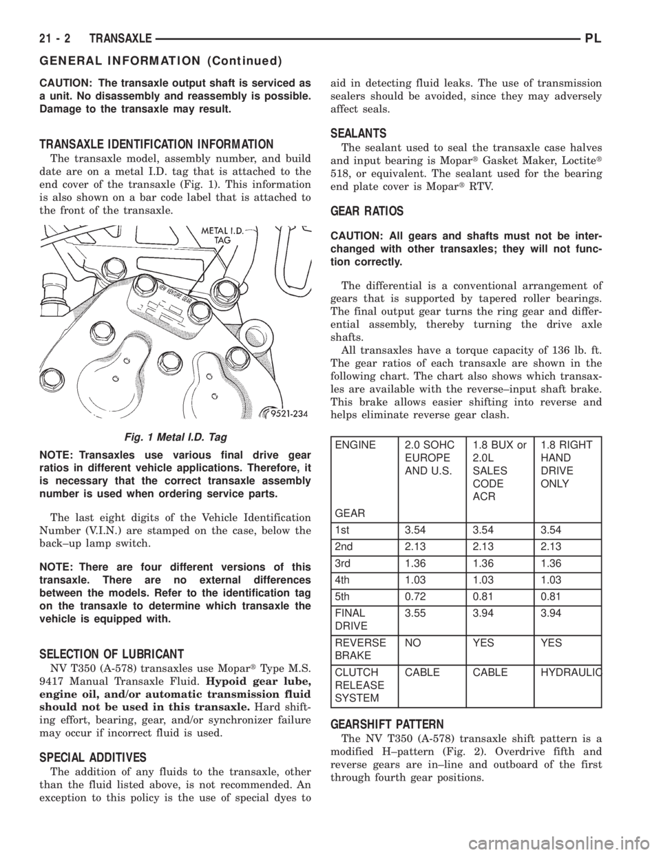
The transaxle model, assembly number, and build
date are on a metal I.D. tag that is attached to the
end cover of the transaxle (Fig. 1). This information
is also shown on a bar code label that is attached to
the front of the transaxle.
NOTE: Transaxles use various final drive gear
ratios in different vehicle applications. Therefore, it
is necessary that the correct transaxle assembly
number is used when ordering service parts.
The last eight digits of the Vehicle Identification
Number (V.I.N.) are stamped on the case, below the
back±up lamp switch.
NOTE: There are four different versions of this
transaxle. There are no external differences
between the models. Refer to the identification tag
on the transaxle to determine which transaxle the
vehicle is equipped with.
SELECTION OF LUBRICANT
NV T350 (A-578) transaxles use MopartType M.S.
9417 Manual Transaxle Fluid.Hypoid gear lube,
engine oil, and/or automatic transmission fluid
should not be used in this transaxle.Hard shift-
ing effort, bearing, gear, and/or synchronizer failure
may occur if incorrect fluid is used.
SPECIAL ADDITIVES
The addition of any fluids to the transaxle, other
than the fluid listed above, is not recommended. An
exception to this policy is the use of special dyes toaid in detecting fluid leaks. The use of transmission
sealers should be avoided, since they may adversely
affect seals.
SEALANTS
The sealant used to seal the transaxle case halves
and input bearing is MopartGasket Maker, Loctitet
518, or equivalent. The sealant used for the bearing
end plate cover is MopartRTV.
GEAR RATIOS
CAUTION: All gears and shafts must not be inter-
changed with other transaxles; they will not func-
tion correctly.
The differential is a conventional arrangement of
gears that is supported by tapered roller bearings.
The final output gear turns the ring gear and differ-
ential assembly, thereby turning the drive axle
shafts.
All transaxles have a torque capacity of 136 lb. ft.
The gear ratios of each transaxle are shown in the
following chart. The chart also shows which transax-
les are available with the reverse±input shaft brake.
This brake allows easier shifting into reverse and
helps eliminate reverse gear clash.
ENGINE 2.0 SOHC
EUROPE
AND U.S.1.8 BUX or
2.0L
SALES
CODE
ACR1.8 RIGHT
HAND
DRIVE
ONLY
GEAR
1st 3.54 3.54 3.54
2nd 2.13 2.13 2.13
3rd 1.36 1.36 1.36
4th 1.03 1.03 1.03
5th 0.72 0.81 0.81
FINAL
DRIVE3.55 3.94 3.94
REVERSE
BRAKENO YES YES
CLUTCH
RELEASE
SYSTEMCABLE CABLE HYDRAULIC
GEARSHIFT PATTERN
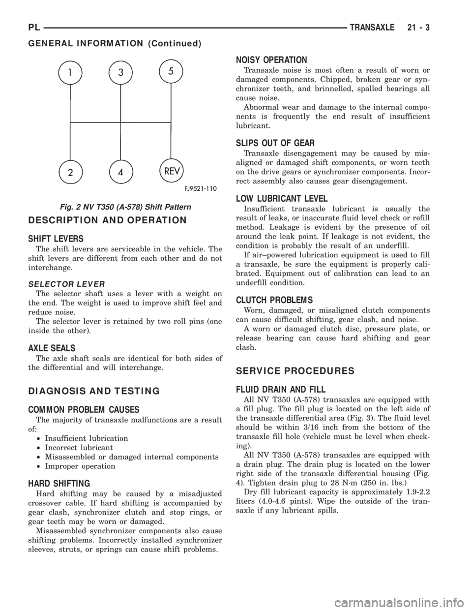
The NV T350 (A-578) transaxle shift pattern is a
modified H±pattern (Fig. 2). Overdrive fifth and
reverse gears are in±line and outboard of the first
through fourth gear positions.
Fig. 1 Metal I.D. Tag
21 - 2 TRANSAXLEPL
GENERAL INFORMATION (Continued)
Page 946 of 1200
DESCRIPTION AND OPERATION
SHIFT LEVERS
The shift levers are serviceable in the vehicle. The
shift levers are different from each other and do not
interchange.
SELECTOR LEVER
The selector shaft uses a lever with a weight on
the end. The weight is used to improve shift feel and
reduce noise.
The selector lever is retained by two roll pins (one
inside the other).
AXLE SEALS
The axle shaft seals are identical for both sides of
the differential and will interchange.
DIAGNOSIS AND TESTING
COMMON PROBLEM CAUSES
The majority of transaxle malfunctions are a result
of:
²Insufficient lubrication
²Incorrect lubricant
²Misassembled or damaged internal components
²Improper operation
HARD SHIFTING
Hard shifting may be caused by a misadjusted
crossover cable. If hard shifting is accompanied by
gear clash, synchronizer clutch and stop rings, or
gear teeth may be worn or damaged.
Misassembled synchronizer components also cause
shifting problems. Incorrectly installed synchronizer
sleeves, struts, or springs can cause shift problems.
NOISY OPERATION
Transaxle noise is most often a result of worn or
damaged components. Chipped, broken gear or syn-
chronizer teeth, and brinnelled, spalled bearings all
cause noise.
Abnormal wear and damage to the internal compo-
nents is frequently the end result of insufficient
lubricant.
SLIPS OUT OF GEAR
Transaxle disengagement may be caused by mis-
aligned or damaged shift components, or worn teeth
on the drive gears or synchronizer components. Incor-
rect assembly also causes gear disengagement.
LOW LUBRICANT LEVEL
Insufficient transaxle lubricant is usually the
result of leaks, or inaccurate fluid level check or refill
method. Leakage is evident by the presence of oil
around the leak point. If leakage is not evident, the
condition is probably the result of an underfill.
If air±powered lubrication equipment is used to fill
a transaxle, be sure the equipment is properly cali-
brated. Equipment out of calibration can lead to an
underfill condition.
CLUTCH PROBLEMS
Worn, damaged, or misaligned clutch components
can cause difficult shifting, gear clash, and noise.
A worn or damaged clutch disc, pressure plate, or
release bearing can cause hard shifting and gear
clash.
SERVICE PROCEDURES
FLUID DRAIN AND FILL
All NV T350 (A-578) transaxles are equipped with
a fill plug. The fill plug is located on the left side of
the transaxle differential area (Fig. 3). The fluid level
should be within 3/16 inch from the bottom of the
transaxle fill hole (vehicle must be level when check-
ing).
All NV T350 (A-578) transaxles are equipped with
a drain plug. The drain plug is located on the lower
right side of the transaxle differential housing (Fig.
4). Tighten drain plug to 28 N´m (250 in. lbs.)
Dry fill lubricant capacity is approximately 1.9-2.2
liters (4.0-4.6 pints). Wipe the outside of the tran-
saxle if any lubricant spills.
Fig. 2 NV T350 (A-578) Shift Pattern
PLTRANSAXLE 21 - 3
GENERAL INFORMATION (Continued)
Page 951 of 1200
SELECTOR LEVER
The selector shaft uses a lever with a weight on
the end. The weight is used to improve shift±feel and
reduce noise.
The selector lever is retained by two roll pins (one
inside the other).
REMOVAL
(1) Remove the selector cable. Refer to Gearshift
Cable removal.
(2) Using a pin punch, remove both roll pins from
the lever.
(3) Pull up and remove the selector lever from the
transaxle selector shaft
INSTALLATION
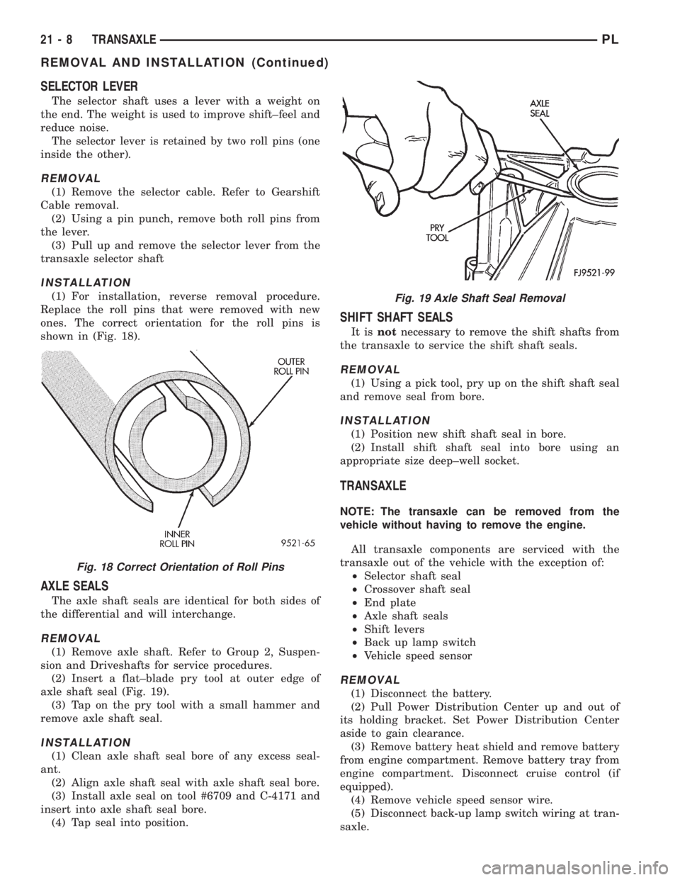
(1) For installation, reverse removal procedure.
Replace the roll pins that were removed with new
ones. The correct orientation for the roll pins is
shown in (Fig. 18).
AXLE SEALS
The axle shaft seals are identical for both sides of
the differential and will interchange.
REMOVAL
(1) Remove axle shaft. Refer to Group 2, Suspen-
sion and Driveshafts for service procedures.
(2) Insert a flat±blade pry tool at outer edge of
axle shaft seal (Fig. 19).
(3) Tap on the pry tool with a small hammer and
remove axle shaft seal.
INSTALLATION
(1) Clean axle shaft seal bore of any excess seal-
ant.
(2) Align axle shaft seal with axle shaft seal bore.
(3) Install axle seal on tool #6709 and C-4171 and
insert into axle shaft seal bore.
(4) Tap seal into position.
SHIFT SHAFT SEALS
It isnotnecessary to remove the shift shafts from
the transaxle to service the shift shaft seals.
REMOVAL
(1) Using a pick tool, pry up on the shift shaft seal
and remove seal from bore.
INSTALLATION
(1) Position new shift shaft seal in bore.
(2) Install shift shaft seal into bore using an
appropriate size deep±well socket.
TRANSAXLE
NOTE: The transaxle can be removed from the
vehicle without having to remove the engine.
All transaxle components are serviced with the
transaxle out of the vehicle with the exception of:
²Selector shaft seal
²Crossover shaft seal
²End plate
²Axle shaft seals
²Shift levers
²Back up lamp switch
²Vehicle speed sensor
REMOVAL
(1) Disconnect the battery.
(2) Pull Power Distribution Center up and out of
its holding bracket. Set Power Distribution Center
aside to gain clearance.
(3) Remove battery heat shield and remove battery
from engine compartment. Remove battery tray from
engine compartment. Disconnect cruise control (if
equipped).
(4) Remove vehicle speed sensor wire.
(5) Disconnect back-up lamp switch wiring at tran-
saxle.
Fig. 18 Correct Orientation of Roll Pins
Fig. 19 Axle Shaft Seal Removal
21 - 8 TRANSAXLEPL
REMOVAL AND INSTALLATION (Continued)
Page 954 of 1200
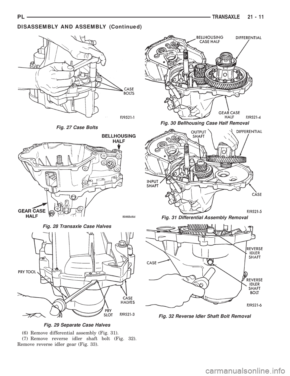
(6) Remove differential assembly (Fig. 31).
(7) Remove reverse idler shaft bolt (Fig. 32).
Remove reverse idler gear (Fig. 33).
Fig. 27 Case Bolts
Fig. 28 Transaxle Case Halves
Fig. 29 Separate Case Halves
Fig. 30 Bellhousing Case Half Removal
Fig. 31 Differential Assembly Removal
Fig. 32 Reverse Idler Shaft Bolt Removal
PLTRANSAXLE 21 - 11
DISASSEMBLY AND ASSEMBLY (Continued)
Page 962 of 1200
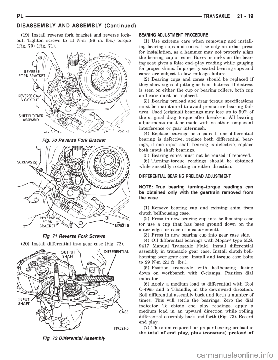
(19) Install reverse fork bracket and reverse lock-
out. Tighten screws to 11 N´m (96 in. lbs.) torque
(Fig. 70) (Fig. 71).
(20) Install differential into gear case (Fig. 72).BEARING ADJUSTMENT PROCEDURE
(1) Use extreme care when removing and install-
ing bearing cups and cones. Use only an arbor press
for installation, as a hammer may not properly align
the bearing cup or cone. Burrs or nicks on the bear-
ing seat gives a false end±play reading while gauging
for proper shims. Improperly seated bearing cups and
cones are subject to low±mileage failure.
(2) Bearing cups and cones should be replaced if
they show signs of pitting or heat distress. If distress
is seen on either the cup or bearing rollers, both cup
and cone must be replaced.
(3) Bearing preload and drag torque specifications
must be maintained to avoid premature bearing fail-
ures. Used (original) bearings may lose up to 50% of
the original drag torque after break±in. All bearing
adjustments must be made with no other component
interference or gear intermesh.
(4) Replace bearings as a pair: If one differential
bearing is defective, replace both differential bear-
ings, if one input shaft bearing is defective, replace
both input shaft bearings.
(5) Bearing cones must not be reused if removed.
(6) Turning±torque readings should be obtained
while smoothly rotating in either direction.
DIFFERENTIAL BEARING PRELOAD ADJUSTMENT
NOTE: True bearing turning±torque readings can
be obtained only with the geartrain removed from
the case.
(1) Remove bearing cup and existing shim from
clutch bellhousing case.
(2) Press in new bearing cup into bellhousing case
(or use a cup that has been ground down on the
outer edge for ease of measurement).
(3) Press in new bearing cup into gear case side.
(4) Oil differential bearings with Moparttype M.S.
9417 Manual Transaxle Fluid. Install differential
assembly in transaxle gear case. Install clutch bell-
housing over gear case. Install and torque case bolts
to 29 N´m (21 ft. lbs.).
(5) Position transaxle with bellhousing facing
down on workbench with C-clamps. Position dial
indicator.
(6) Apply a medium load to differential with Tool
C-4995 and a T-handle, in the downward direction.
Roll differential assembly back and forth a number of
times. This will settle the bearings. Zero the dial
indicator. To obtain end play readings, apply a
medium load in an upward direction while rolling
differential assembly back and forth (Fig. 73). Record
end play.
(7) The shim required for proper bearing preload is
thetotal of end play, plus (constant) preload of
Fig. 70 Reverse Fork Bracket
Fig. 71 Reverse Fork Screws
Fig. 72 Differential Assembly
PLTRANSAXLE 21 - 19
DISASSEMBLY AND ASSEMBLY (Continued)
Page 963 of 1200
0.18mm (0.007 in.).Never combine shims to obtain
the required preload.
(8) Remove case bolts. Remove clutch bellhousing
differential bearing cup. Install shim(s) selected in
Step 7. Then press the bearing cup into clutch bell-
housing.
(9) Install clutch bellhousing. Install and torque
case bolts to 26 N´m (19 ft. lbs.).
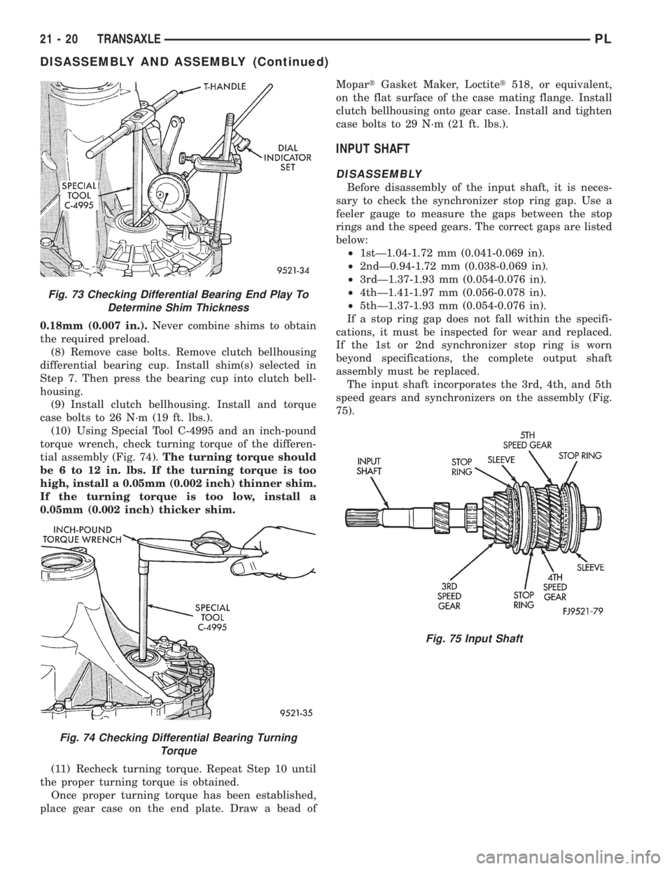
(10) Using Special Tool C-4995 and an inch-pound
torque wrench, check turning torque of the differen-
tial assembly (Fig. 74).The turning torque should
be 6 to 12 in. lbs. If the turning torque is too
high, install a 0.05mm (0.002 inch) thinner shim.
If the turning torque is too low, install a
0.05mm (0.002 inch) thicker shim.
(11) Recheck turning torque. Repeat Step 10 until
the proper turning torque is obtained.
Once proper turning torque has been established,
place gear case on the end plate. Draw a bead ofMopartGasket Maker, Loctitet518, or equivalent,
on the flat surface of the case mating flange. Install
clutch bellhousing onto gear case. Install and tighten
case bolts to 29 N´m (21 ft. lbs.).
INPUT SHAFT
DISASSEMBLY
Before disassembly of the input shaft, it is neces-
sary to check the synchronizer stop ring gap. Use a
feeler gauge to measure the gaps between the stop
rings and the speed gears. The correct gaps are listed
below:
²1stÐ1.04-1.72 mm (0.041-0.069 in).
²2ndÐ0.94-1.72 mm (0.038-0.069 in).
²3rdÐ1.37-1.93 mm (0.054-0.076 in).
²4thÐ1.41-1.97 mm (0.056-0.078 in).
²5thÐ1.37-1.93 mm (0.054-0.076 in).
If a stop ring gap does not fall within the specifi-
cations, it must be inspected for wear and replaced.
If the 1st or 2nd synchronizer stop ring is worn
beyond specifications, the complete output shaft
assembly must be replaced.
The input shaft incorporates the 3rd, 4th, and 5th
speed gears and synchronizers on the assembly (Fig.
75).
Fig. 73 Checking Differential Bearing End Play To
Determine Shim Thickness
Fig. 74 Checking Differential Bearing Turning
Torque
Fig. 75 Input Shaft
21 - 20 TRANSAXLEPL
DISASSEMBLY AND ASSEMBLY (Continued)
Page 967 of 1200
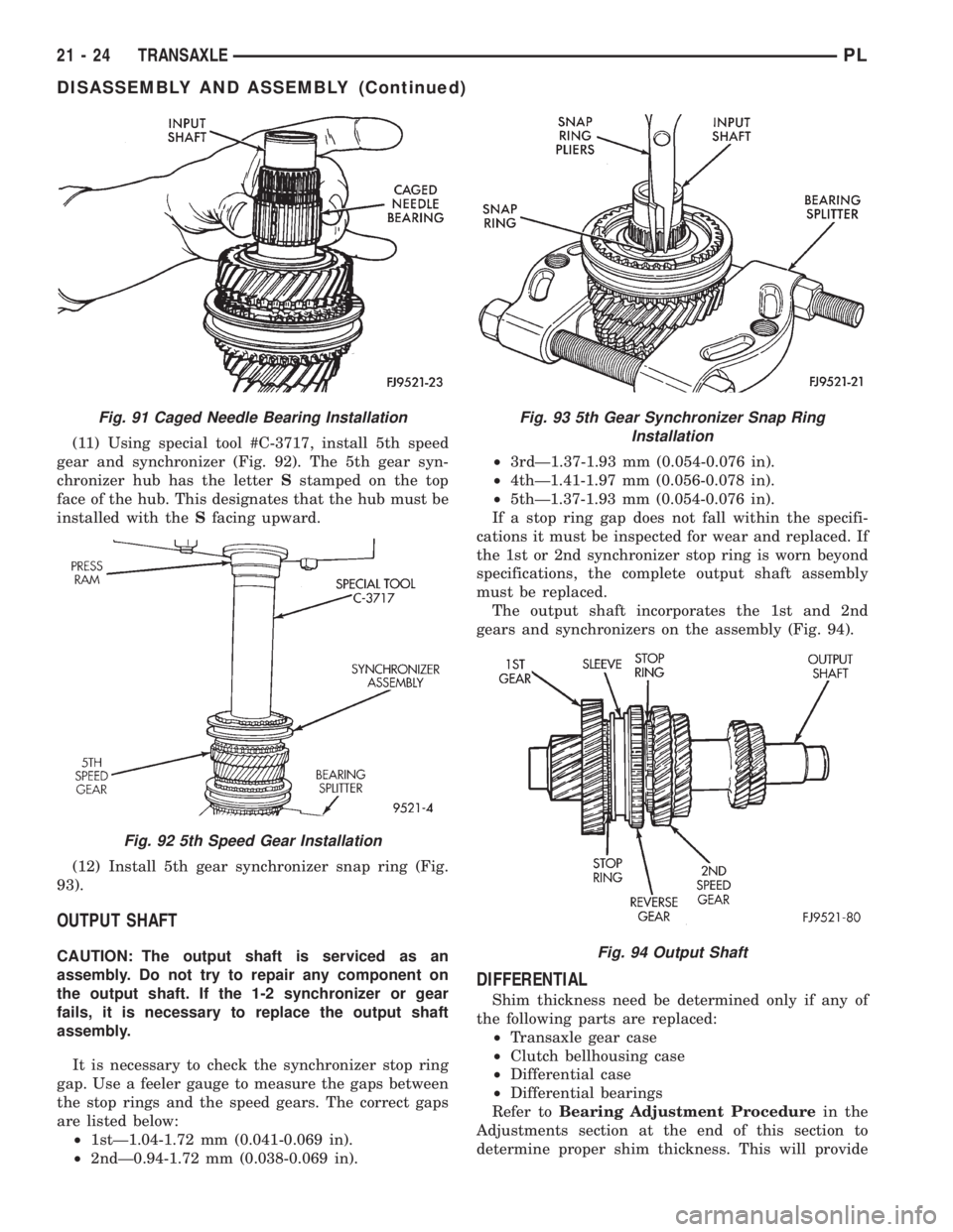
(11) Using special tool #C-3717, install 5th speed
gear and synchronizer (Fig. 92). The 5th gear syn-
chronizer hub has the letterSstamped on the top
face of the hub. This designates that the hub must be
installed with theSfacing upward.
(12) Install 5th gear synchronizer snap ring (Fig.
93).
OUTPUT SHAFT
CAUTION: The output shaft is serviced as an
assembly. Do not try to repair any component on
the output shaft. If the 1-2 synchronizer or gear
fails, it is necessary to replace the output shaft
assembly.
It is necessary to check the synchronizer stop ring
gap. Use a feeler gauge to measure the gaps between
the stop rings and the speed gears. The correct gaps
are listed below:
²1stÐ1.04-1.72 mm (0.041-0.069 in).
²2ndÐ0.94-1.72 mm (0.038-0.069 in).²3rdÐ1.37-1.93 mm (0.054-0.076 in).
²4thÐ1.41-1.97 mm (0.056-0.078 in).
²5thÐ1.37-1.93 mm (0.054-0.076 in).
If a stop ring gap does not fall within the specifi-
cations it must be inspected for wear and replaced. If
the 1st or 2nd synchronizer stop ring is worn beyond
specifications, the complete output shaft assembly
must be replaced.
The output shaft incorporates the 1st and 2nd
gears and synchronizers on the assembly (Fig. 94).
DIFFERENTIAL
Shim thickness need be determined only if any of
the following parts are replaced:
²Transaxle gear case
²Clutch bellhousing case
²Differential case
²Differential bearings
Refer toBearing Adjustment Procedurein the
Adjustments section at the end of this section to
determine proper shim thickness. This will provide
Fig. 91 Caged Needle Bearing Installation
Fig. 92 5th Speed Gear Installation
Fig. 93 5th Gear Synchronizer Snap Ring
Installation
Fig. 94 Output Shaft
21 - 24 TRANSAXLEPL
DISASSEMBLY AND ASSEMBLY (Continued)