1999 DODGE NEON fuse
[x] Cancel search: fusePage 368 of 1200
ELECTRICALLY HEATED SYSTEMS
CONTENTS
page page
DIAGNOSIS AND TESTING
REAR WINDOW DEFOGGER SWITCH....... 1REMOVAL AND INSTALLATION
REAR WINDOW DEFOGGER AND/OR REAR
FOG LAMP SWITCH................... 2
DIAGNOSIS AND TESTING
REAR WINDOW DEFOGGER SWITCH
The rear window defogger switch may be tested in-
vehicle or bench tested. In vehicle testing is accom-
plished in the following manner:
(1) Remove the switch from the instrument panel
but leave the switch connected, refer to Group 8E,
Instrument Panel and Systems for removal proce-
dures.
(2) Turn the ignition switch ON.
(3) Using a voltmeter, check for battery voltage at
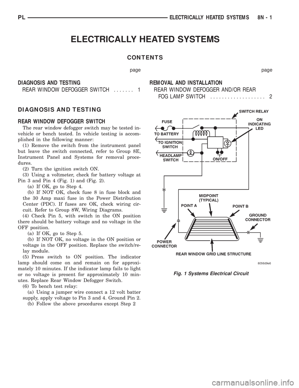
Pin 3 and Pin 4 (Fig. 1) and (Fig. 2).
(a) If OK, go to Step 4.
(b) If NOT OK, check fuse 8 in fuse block and
the 30 Amp maxi fuse in the Power Distribution
Center (PDC). If fuses are OK, check wiring cir-
cuit. Refer to Group 8W, Wiring Diagrams.
(4) Check Pin 5, with switch in the ON position
there should be battery voltage and no voltage in the
OFF position.
(a) If OK, go to Step 5.
(b) If NOT OK, no voltage in the ON position or
voltage in the OFF position. Replace the switch/re-
lay module.
(5) Press switch to ON position. The indicator
lamp should come on and remain on for approxi-
mately 10 minutes. If the indicator lamp fails to light
or no voltage is present for approximately 10 min-
utes. Replace Rear Window Defogger Switch.
(6) To bench test relay:
(a) Using a jumper wire connect a 12 volt batter
supply, apply voltage to Pin 3 and 4. Ground Pin 2.
(b) Follow the above procedures except Step 2
Fig. 1 Systems Electrical Circuit
PLELECTRICALLY HEATED SYSTEMS 8N - 1
Page 371 of 1200

(3) Connect one lead of test light to a ground ter-
minal. Touch other test light lead to Red Wire termi-
nal.
(a) If test light comes on, the wiring circuit
between the battery and switch is functional.
(b) If test light does not come on, check fuse 3 in
the fuse block or for a open circuit.
(4) If test light comes on, the wiring circuit
between the battery and switch is functional.
REMOVAL AND INSTALLATION
DOOR LOCK MOTOR
REMOVAL
(1) Remove door trim panel, refer to Group 23,
Body for removal procedures.
(2) Disconnect all door linkages at the latch/lock
assembly (Fig. 1).
(3) Disconnect motor wire connector.
(4) Remove latch/lock assembly attaching screws
and remove assembly.
INSTALLATION
For installation, reverse the above procedures.
DOOR LOCK SWITCH
REMOVAL
(1) Remove front door trim, refer to Group 23,
Body for proper procedures.
(2) Disconnect wire connector.
(3) Remove attaching screws.
(4) Remove the switch.
INSTALLATION
For installation, reverse the above procedures.
Fig. 1 Door Latch Assembly
Fig. 2 Door Lock Switch Continuity Test
8P - 2 POWER DOOR LOCKSPL
DIAGNOSIS AND TESTING (Continued)
Page 374 of 1200
parking lamps out put. Press the panic button and
check for a voltage pulse (Fig. 2).
(2) If no voltage pulse is measured, replace the
receiver. If voltage OK, repair circuit to the parking
lamps as necessary.
(3) Connect the meter to Pin 5 of the black connec-
tor and to ground to test head lamps out put. Press
the panic button and check for a voltage pulse (Fig.
2).
(4) If no voltage pulse is measured, replace the
receiver. If voltage OK, repair circuit to the head
lamps as necessary.
REMOTE KEYLESS ENTRY SYSTEM
When trouble shooting problems with the Remote
Keyless Entry System, always verify that the power
door lock/unlock switches are functional. If the doors
do not lock/unlock refer to Group 8W, Wiring Dia-
gram for Pin and wiring locations.
If the following items do not work:
²Remote keyless entry system
²Radio/clock
²Door lock switches
A blown fuse is the probable cause. Check fuses 2,
3 and 11 in the fuse block. To check for a blown fuse,
pull the fuse out slightly, but maintain contact
between the fuse terminals and the terminals in fuse
block. Using the voltmeter probe, check both termi-
nals for 12 volts. If only one terminal measures bat-
tery voltage, the circuit breaker is defective and must
be replaced. If neither terminal measures battery
voltage, check the high current fuses 3 and 11 in the
Power Distribution Center (PDC). The PDC is located
in the engine compartment. If fuse(s) are NOT OK,
replace fuse(s) or repair as necessary. If fuses are
OK, check for an open or shorted circuit to the Power
Distribution Center, repair as needed.
SERVICE PROCEDURES
HORN CHIRP CANCELLATION
During the programming operation the horn chirp
can be disabled or enable using the following proce-
dure. One or both transmitters can be program to be
disabled or enable.
(1) Retrieve the programming line from the upper
edge of the passenger side cowl trim panel upper
edge. The RKE Programming Line is a green wire
with a red bullet connector.
(2) Using a jumper wire, ground the RKE pro-
gramming line.
(3) Turn ignition switch to the ON position.
(4) Press any button on the transmitter. The locks
will cycle to confirm programming,
(5) To disable or enable horn chirp press the lock
button on the transmitter four times and the hornwill sound to confirm programming. Press the lock
button on the second transmitter four times and the
horn will sound to confirm programming.
(6) Disconnect the programming line from ground.
This returns the system to its normal operation
mode.
(7) Replace any removed components. Return pro-
gramming line chirpto its original position. Check for
system operation.
PANIC FUNCTION CANCELLATION
During the programming operation the panic func-
tion can be disabled or enable using the following
procedure. One or both transmitters can be program
to be disabled or enable.
(1) Retrieve the programming line from the upper
edge of the passenger side cowl trim panel. The RKE
Program Line is a green wire with a red bullet con-
nector.
(2) Using a jumper wire, ground the RKE Pro-
gramming Line.
(3) Turn ignition switch to the ON position.
(4) Press any button on the transmitter. The locks
will cycle to confirm programming,
(5) To disable or enable panic function press the
panic button on the transmitter four times and the
horn will sound to confirm programming. Press the
panic button on the second transmitter four times
and the horn will sound to confirm programming.
(6) Disconnect the programming line from ground.
This returns the system to its normal operation
mode.
(7) Replace any removed components. Return the
programming line to its original position. Check for
system operation.
PROGRAM REMOTE KEYLESS ENTRY MODULE
(1) Retrieve the programming line from the upper
edge of the passenger side cowl trim panel. The RKE
Programming Line is a green wire with a red bullet
connector.
(2) Using a jumper wire, ground the RKE pro-
gramming line.
(3) Turn ignition switch to the ON position.
(4) Press any button on the transmitter to set
code. The locks will cycle to confirm programming. If
there is a second transmitter it must be set at this
time. Press any button on the second transmitter and
wait for the locks to cycle to confirm programming.
(5) Disconnect the programming line from ground.
This returns the system to its normal operation
mode.
(6) Replace all removed components. Return pro-
gramming line to its original position. Check for sys-
tem operation.
PLPOWER DOOR LOCKS 8P - 5
DIAGNOSIS AND TESTING (Continued)
Page 378 of 1200
SERVICE PROCEDURES
VEHICLE IMMOBILIZER SYSTEM
WARNING: ON VEHICLES EQUIPPED WITH AIR-
BAGS, REFER TO GROUP 8M - PASSIVE
RESTRAINT SYSTEMS BEFORE ATTEMPTING ANY
STEERING WHEEL, STEERING COLUMN, OR
INSTRUMENT PANEL COMPONENT DIAGNOSIS OR
SERVICE. FAILURE TO TAKE THE PROPER PRE-
CAUTIONS COULD RESULT IN ACCIDENTAL AIR-
BAG DEPLOYMENT AND POSSIBLE PERSONAL
INJURY.
NOTE: The following tests may not prove conclu-
sive in the diagnosis of this system. The most reli-
able, efficient, and accurate means to diagnose the
Vehicle Immobilizer System involves the use of a
DRB scan tool. Refer to the Vehicle Theft Security
System menu item on the DRB scan tool for the
procedures.
The vehicle immobilizer system and the Chrysler
Collision Detection (CCD) data bus network should
be diagnosed using the DRB scan tool. The DRB will
allow confirmation that the CCD data bus is func-
tional, that the immobilizer receiver is placing the
proper messages on the CCD data bus, and that the
Powertrain Control Module (PCM) is receiving the
CCD data bus messages. Refer to the Vehicle Theft
Security System menu item on the DRB scan tool for
the procedures. Refer to 8W-39 - Vehicle Theft Secu-
rity System in Group 8W - Wiring Diagrams for com-
plete circuit descriptions and diagrams.
(1) With the ignition switch in the Off position,
depress the Lock or Unlock button of the immobilizer
transmitter. Listen for the immobilizer receiver to
issue an audible chirp (Unlock) or chirps (Lock). If
OK, go to Step 2. If not OK, replace the transmitter
batteries with known good units and repeat Step 1. If
still not OK, go to Step 2.
(2) Check the fuse in the Power Distribution Cen-
ter (PDC). If OK, go to Step 3. If not OK, repair the
shorted circuit or component as required and replace
the faulty fuse.
(3) Disconnect and isolate the battery negative
cable. Unplug the wire harness connector at the
immobilizer receiver. Check for continuity between
the ground circuit cavity of the immobilizer receiver
wire harness connector and a good ground. There
should be continuity. If OK, go to Step 4. If not OK,
repair the open circuit to ground as required.
(4) Connect the battery negative cable. Check for
battery voltage at the fused B(+) circuit cavity of the
immobilizer receiver wire harness connector. If OK,
refer to the Vehicle Theft Security System menu itemon the DRB scan tool for further diagnosis. If not
OK, repair the open circuit to the PDC fuse as
required.REMOVAL AND INSTALLATION
IMMOBILIZER RECEIVER
WARNING: ON VEHICLES EQUIPPED WITH AIR-
BAGS, REFER TO GROUP 8M - PASSIVE
RESTRAINT SYSTEMS BEFORE ATTEMPTING ANY
STEERING WHEEL, STEERING COLUMN, OR
INSTRUMENT PANEL COMPONENT DIAGNOSIS OR
SERVICE. FAILURE TO TAKE THE PROPER PRE-
CAUTIONS COULD RESULT IN ACCIDENTAL AIR-
BAG DEPLOYMENT AND POSSIBLE PERSONAL
INJURY.
(1) Disconnect and isolate the battery negative
cable.
(2) Remove the Instrument Panel Top Cover and
Cluster Bezel and Right Trim panel. Remove the
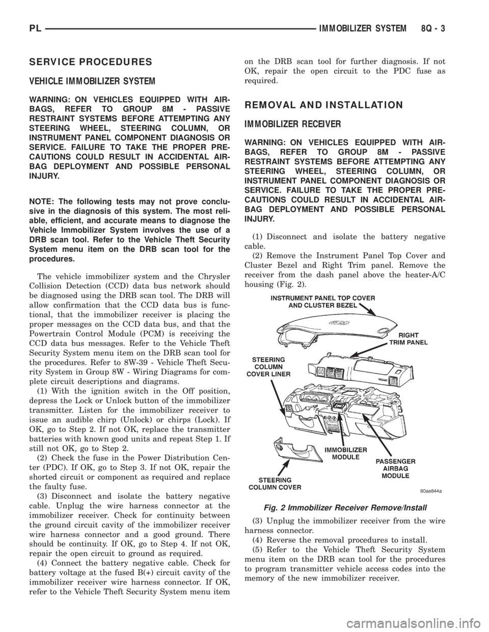
receiver from the dash panel above the heater-A/C
housing (Fig. 2).
(3) Unplug the immobilizer receiver from the wire
harness connector.
(4) Reverse the removal procedures to install.
(5) Refer to the Vehicle Theft Security System
menu item on the DRB scan tool for the procedures
to program transmitter vehicle access codes into the
memory of the new immobilizer receiver.
Fig. 2 Immobilizer Receiver Remove/Install
PLIMMOBILIZER SYSTEM 8Q - 3
Page 380 of 1200
POWER WINDOWS
CONTENTS
page page
GENERAL INFORMATION
INTRODUCTION......................... 1
DIAGNOSIS AND TESTING
WINDOW MOTOR TEST................... 1
WINDOW SWITCH TEST.................. 1WIRING TEST........................... 1
REMOVAL AND INSTALLATION
2 DOOR WINDOW MOTOR................ 2
4 DOOR WINDOW MOTOR................ 3
WINDOW SWITCH....................... 2
GENERAL INFORMATION
INTRODUCTION
The window lift motors are of the permanent mag-
net type. A battery positive and negative connection
to either of the two motor terminals will cause the
motor to rotate in one direction. Reversing current
through these same two connections will cause the
motor to rotate in the opposite direction.
Each individual motor is grounded through the
master switch.
DIAGNOSIS AND TESTING
WIRING TEST
The following wiring test determines whether or
not voltage is continuous through the body harness
to switch.
Remove switch for testing. Connect a voltmeter
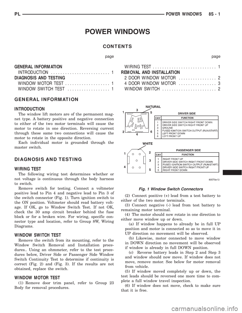
positive lead to Pin 4 and negative lead to Pin 3 of
the switch connector (Fig. 1). Turn ignition switch to
the ON position. Voltmeter should read battery volt-
age. If OK, go to Window Switch Test. If not OK,
check the 30 amp circuit breaker behind the fuse
block or for a broken wire. For wiring, specific con-
nector type and location, refer to Group 8W, Wiring
Diagrams.
WINDOW SWITCH TEST
Remove the switch from its mounting, refer to the
Window Switch Removal and Installation proce-
dures.. Using an ohmmeter, refer to the test proce-
dures below, Driver Side or Passenger Side Window
Switch Continuity Test to determine if continuity is
correct (Fig. 2) and (Fig. 3). If the results are not
obtained, replace the switch.
WINDOW MOTOR TEST
(1) Remove door trim panel, refer to Group 23
Body for removal procedures.(2) Connect positive (+) lead from a test battery to
either of the two motor terminals.
(3) Connect negative (-) lead from test battery to
remaining motor terminal.
(4) The motor should now rotate in one direction to
either move window up or down.
(a) If window happens to already be in full UP
position and motor is connected so as to move it in
UP direction no movement will be observed.
(b) Likewise, motor connected to move window
in DOWN direction no movement will be observed
if window is already in full DOWN position.
(c) Reverse battery leads in Step 2 and Step 3
and window should now move. If window does not
move, remove motor. See below for motor removal
from vehicle.
(5) If window moved completely up or down, the
test leads should be reversed one more time to com-
plete a full window travel inspection.
(6) If window does not move, check to make sure
that it is free.
Fig. 1 Window Switch Connectors
PLPOWER WINDOWS 8S - 1
Page 384 of 1200
POWER MIRRORS
CONTENTS
page page
GENERAL INFORMATION
INTRODUCTION......................... 1
DIAGNOSIS AND TESTING
MIRROR MOTOR........................ 2
MIRROR SWITCH TEST................... 1REMOVAL AND INSTALLATION
INSIDE MIRROR/READING LAMPS
ASSEMBLY............................ 2
INSIDE MIRROR/READING LAMPS
BULB/LENS........................... 2
MIRROR ASSEMBLY..................... 2
MIRROR SWITCH........................ 2
GENERAL INFORMATION
INTRODUCTION
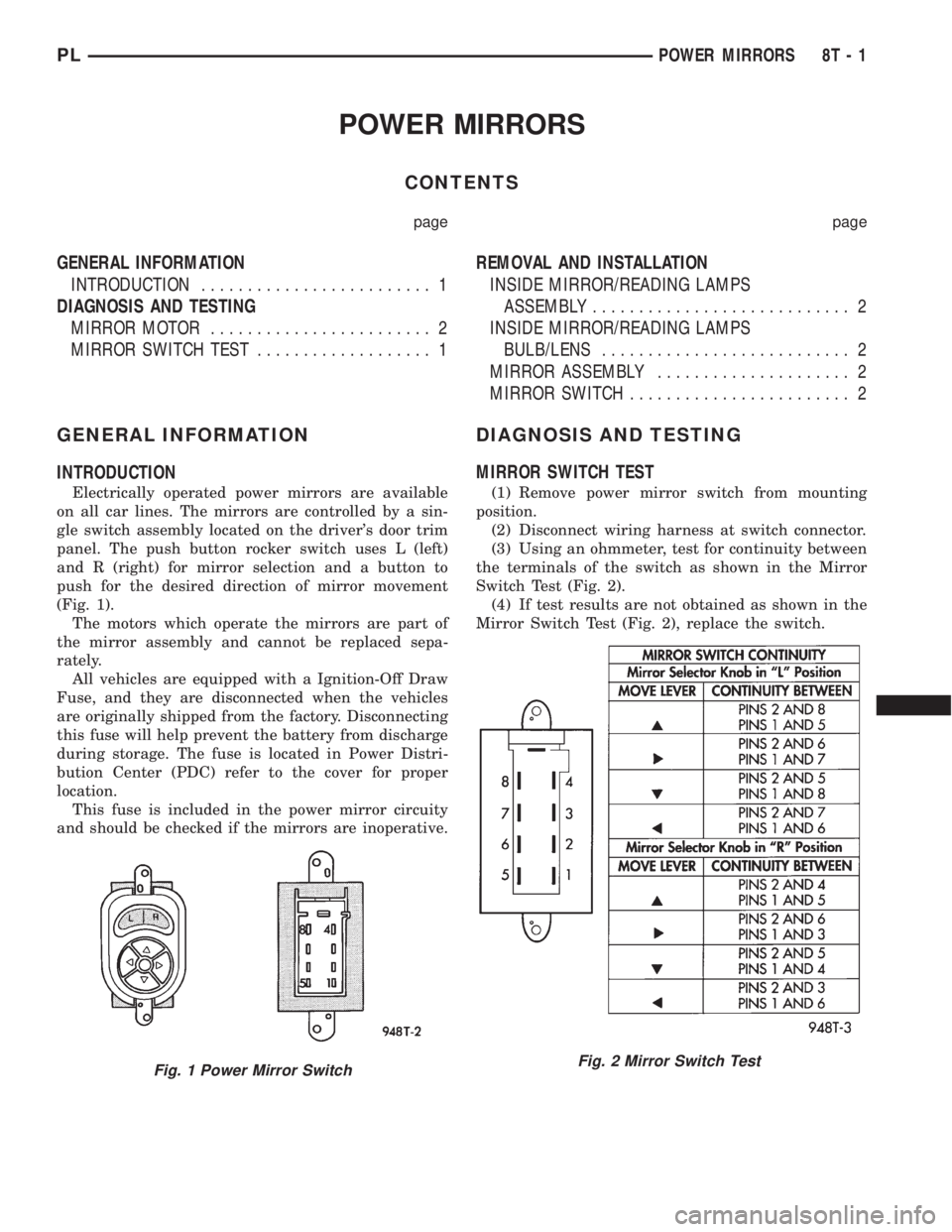
Electrically operated power mirrors are available
on all car lines. The mirrors are controlled by a sin-
gle switch assembly located on the driver's door trim
panel. The push button rocker switch uses L (left)
and R (right) for mirror selection and a button to
push for the desired direction of mirror movement
(Fig. 1).
The motors which operate the mirrors are part of
the mirror assembly and cannot be replaced sepa-
rately.
All vehicles are equipped with a Ignition-Off Draw
Fuse, and they are disconnected when the vehicles
are originally shipped from the factory. Disconnecting
this fuse will help prevent the battery from discharge
during storage. The fuse is located in Power Distri-
bution Center (PDC) refer to the cover for proper
location.
This fuse is included in the power mirror circuity
and should be checked if the mirrors are inoperative.
DIAGNOSIS AND TESTING
MIRROR SWITCH TEST
(1) Remove power mirror switch from mounting
position.
(2) Disconnect wiring harness at switch connector.
(3) Using an ohmmeter, test for continuity between
the terminals of the switch as shown in the Mirror
Switch Test (Fig. 2).
(4) If test results are not obtained as shown in the
Mirror Switch Test (Fig. 2), replace the switch.
Fig. 1 Power Mirror SwitchFig. 2 Mirror Switch Test
PLPOWER MIRRORS 8T - 1
Page 386 of 1200
POWER MIRRORS
CONTENTS
page page
GENERAL INFORMATION
INTRODUCTION........................ 1
DIAGNOSIS AND TESTING
MIRROR MOTOR....................... 2MIRROR SWITCH TEST.................. 1
GENERAL INFORMATION
INTRODUCTION
Right Hand Drive (RHD) vehicles may be equipped
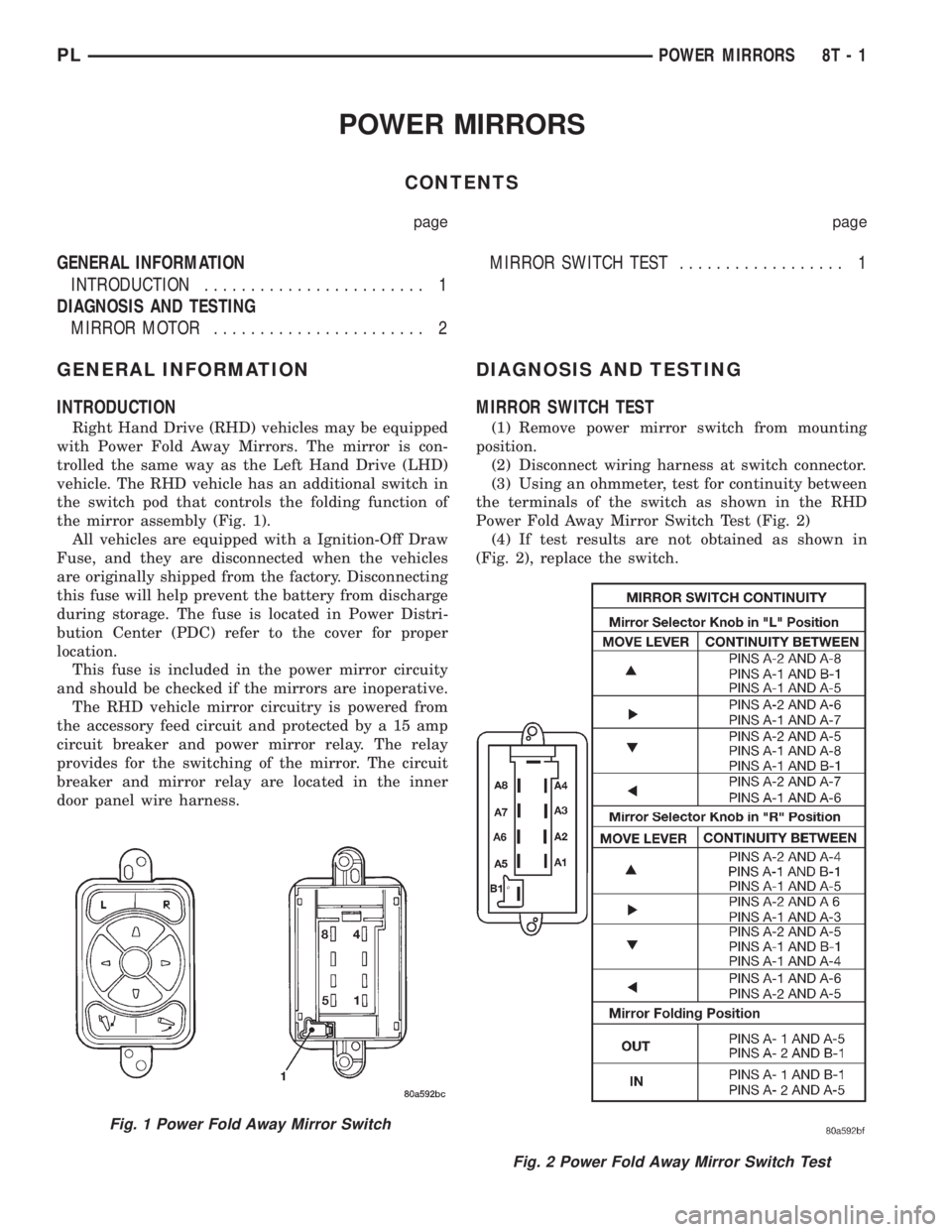
with Power Fold Away Mirrors. The mirror is con-
trolled the same way as the Left Hand Drive (LHD)
vehicle. The RHD vehicle has an additional switch in
the switch pod that controls the folding function of
the mirror assembly (Fig. 1).
All vehicles are equipped with a Ignition-Off Draw
Fuse, and they are disconnected when the vehicles
are originally shipped from the factory. Disconnecting
this fuse will help prevent the battery from discharge
during storage. The fuse is located in Power Distri-
bution Center (PDC) refer to the cover for proper
location.
This fuse is included in the power mirror circuity
and should be checked if the mirrors are inoperative.
The RHD vehicle mirror circuitry is powered from
the accessory feed circuit and protected by a 15 amp
circuit breaker and power mirror relay. The relay
provides for the switching of the mirror. The circuit
breaker and mirror relay are located in the inner
door panel wire harness.
DIAGNOSIS AND TESTING
MIRROR SWITCH TEST
(1) Remove power mirror switch from mounting
position.
(2) Disconnect wiring harness at switch connector.
(3) Using an ohmmeter, test for continuity between
the terminals of the switch as shown in the RHD
Power Fold Away Mirror Switch Test (Fig. 2)
(4) If test results are not obtained as shown in
(Fig. 2), replace the switch.
Fig. 1 Power Fold Away Mirror Switch
Fig. 2 Power Fold Away Mirror Switch Test
PLPOWER MIRRORS 8T - 1
Page 392 of 1200
WIRING DIAGRAMS
CONTENTS
page page
AIR CONDITIONING-HEATER.......... 8W-42-1
AIRBAG SYSTEM................... 8W-43-1
ANTI-LOCK BRAKES................. 8W-35-1
AUDIO SYSTEMS................... 8W-47-1
CHARGING SYSTEM................. 8W-20-1
COMPONENT INDEX................. 8W-02-1
CONNECTOR/GROUND LOCATIONS..... 8W-90-1
CONNECTOR PIN-OUTS.............. 8W-80-1
FRONT LIGHTING................... 8W-50-1
FUEL/IGNITION SYSTEMS............ 8W-30-1
FUSE BLOCK....................... 8W-11-1
GENERAL INFORMATION............. 8W-01-1
GROUND DISTRIBUTION............. 8W-15-1
HORN/CIGAR LIGHTER............... 8W-41-1INSTRUMENT CLUSTER.............. 8W-40-1
INTERIOR LIGHTING................. 8W-44-1
POWER DISTRIBUTION.............. 8W-10-1
POWER DOOR LOCKS............... 8W-61-1
POWER MIRRORS.................. 8W-62-1
POWER SUNROOF.................. 8W-64-1
POWER WINDOWS.................. 8W-60-1
REAR LIGHTING.................... 8W-51-1
REAR WINDOW DEFOGGER........... 8W-48-1
SPLICE INFORMATION............... 8W-70-1
SPLICE LOCATIONS................. 8W-95-1
STARTING SYSTEM................. 8W-21-1
TURN SIGNALS..................... 8W-52-1
WIPERS........................... 8W-53-1
PLWIRING DIAGRAMS 8W - 1