1999 DODGE NEON fuse
[x] Cancel search: fusePage 877 of 1200
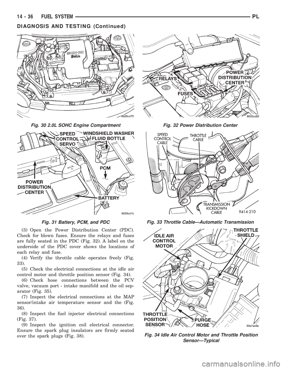
(3) Open the Power Distribution Center (PDC).
Check for blown fuses. Ensure the relays and fuses
are fully seated in the PDC (Fig. 32). A label on the
underside of the PDC cover shows the locations of
each relay and fuse.
(4) Verify the throttle cable operates freely (Fig.
33).
(5) Check the electrical connections at the idle air
control motor and throttle position sensor (Fig. 34).
(6) Check hose connections between the PCV
valve, vacuum port - intake manifold and the oil sep-
arator (Fig. 35).
(7) Inspect the electrical connections at the MAP
sensor/intake air temperature sensor and the (Fig.
36).
(8) Inspect the fuel injector electrical connections
(Fig. 37).
(9) Inspect the ignition coil electrical connector.
Ensure the spark plug insulators are firmly seated
over the spark plugs (Fig. 38).
Fig. 30 2.0L SOHC Engine Compartment
Fig. 31 Battery, PCM, and PDC
Fig. 32 Power Distribution Center
Fig. 33 Throttle CableÐAutomatic Transmission
Fig. 34 Idle Air Control Motor and Throttle Position
SensorÐTypical
14 - 36 FUEL SYSTEMPL
DIAGNOSIS AND TESTING (Continued)
Page 882 of 1200
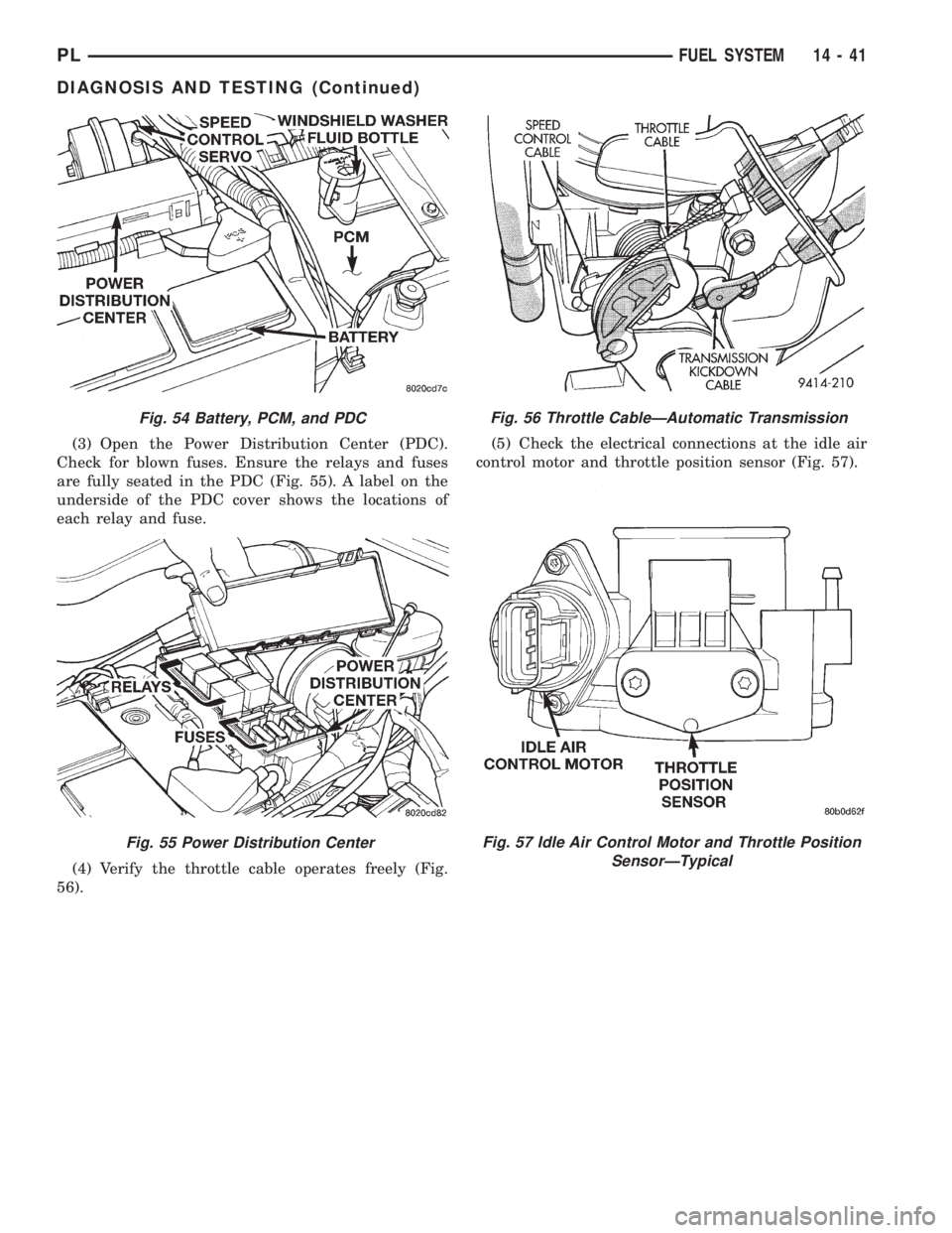
(3) Open the Power Distribution Center (PDC).
Check for blown fuses. Ensure the relays and fuses
are fully seated in the PDC (Fig. 55). A label on the
underside of the PDC cover shows the locations of
each relay and fuse.
(4) Verify the throttle cable operates freely (Fig.
56).(5) Check the electrical connections at the idle air
control motor and throttle position sensor (Fig. 57).
Fig. 54 Battery, PCM, and PDC
Fig. 55 Power Distribution Center
Fig. 56 Throttle CableÐAutomatic Transmission
Fig. 57 Idle Air Control Motor and Throttle Position
SensorÐTypical
PLFUEL SYSTEM 14 - 41
DIAGNOSIS AND TESTING (Continued)
Page 1128 of 1200
SUNROOF
INDEX
page page
DIAGNOSIS AND TESTING
DIAGNOSTIC PROCEDURES............... 47
SUNROOF DIAGNOSIS................... 47
REMOVAL AND INSTALLATION
SUNROOF CABLES...................... 48
SUNROOF COMPONENTS................ 49
SUNROOF DRIVE MOTOR................. 49
SUNROOF GLASS PANEL................. 49SUNROOF GUIDE AND MECHANISM
ASSEMBLY........................... 49
SUNROOF MODULE..................... 50
SUNROOF PROCEDURE INFORMATION...... 48
SUNROOF SUNSHADE................... 50
SUNROOF WIND DEFLECTOR............. 51
ADJUSTMENTS
SUNROOF GLASS HEIGHT ADJUSTMENT.... 51
DIAGNOSIS AND TESTING
DIAGNOSTIC PROCEDURES
Before beginning sunroof diagnostics verify that all
other power accessories are in proper operating con-
dition. If not, a common electrical problem may exist.
Refer to the Wiring Diagrams section of this publica-tion for circuit, splice and component descriptions.
Check the condition of the circuit protection (fuses,
circuit breakers or fuse links). Inspect all wiring con-
nector pins for proper engagement and continuity.
Check for battery voltage at the power sunroof con-
trol switches. If battery voltage is detected at the
control switches, proceed with the following tests.
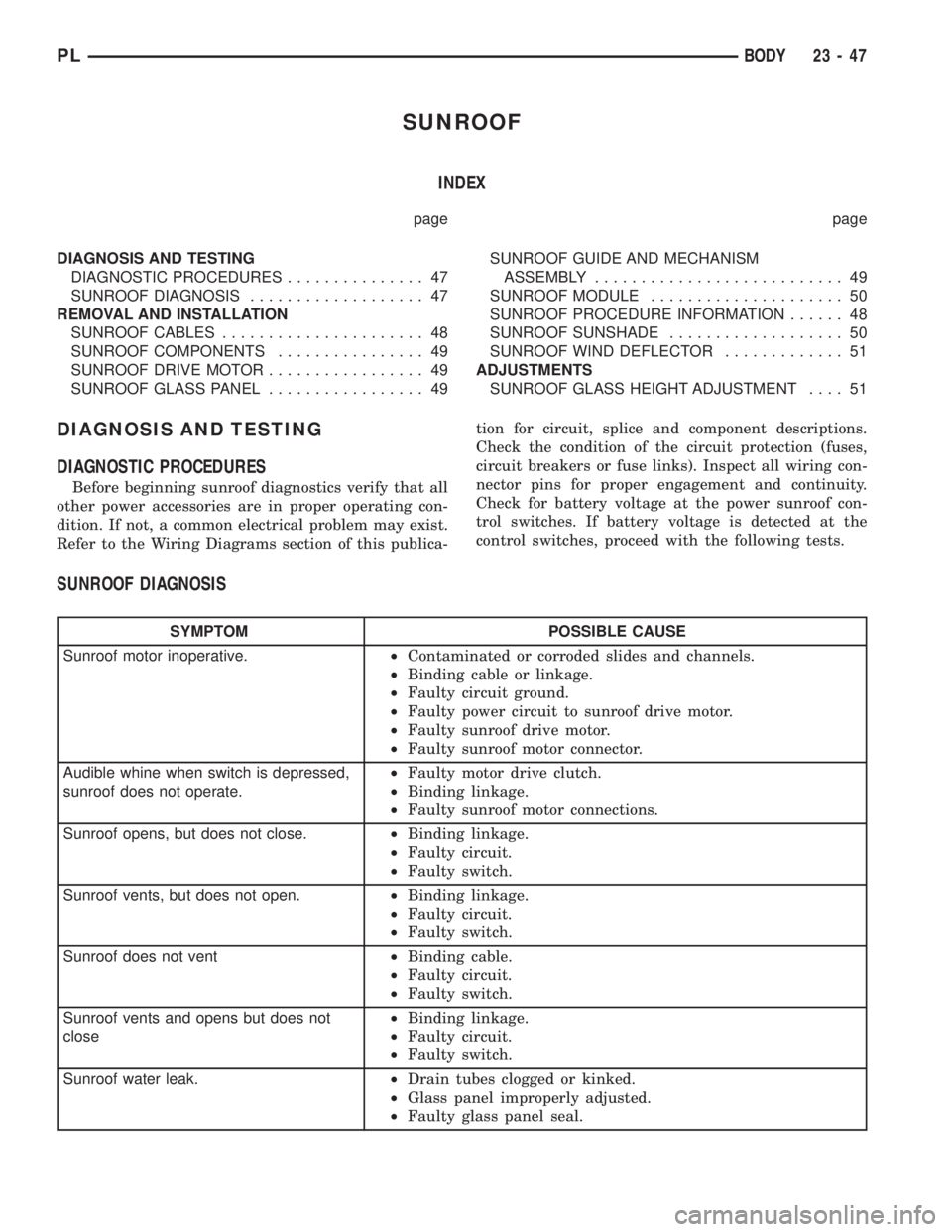
SUNROOF DIAGNOSIS
SYMPTOM POSSIBLE CAUSE
Sunroof motor inoperative.²Contaminated or corroded slides and channels.
²Binding cable or linkage.
²Faulty circuit ground.
²Faulty power circuit to sunroof drive motor.
²Faulty sunroof drive motor.
²Faulty sunroof motor connector.
Audible whine when switch is depressed,
sunroof does not operate.²Faulty motor drive clutch.
²Binding linkage.
²Faulty sunroof motor connections.
Sunroof opens, but does not close.²Binding linkage.
²Faulty circuit.
²Faulty switch.
Sunroof vents, but does not open.²Binding linkage.
²Faulty circuit.
²Faulty switch.
Sunroof does not vent²Binding cable.
²Faulty circuit.
²Faulty switch.
Sunroof vents and opens but does not
close²Binding linkage.
²Faulty circuit.
²Faulty switch.
Sunroof water leak.²Drain tubes clogged or kinked.
²Glass panel improperly adjusted.
²Faulty glass panel seal.
PLBODY 23 - 47
Page 1141 of 1200
(3) Close all doors, windows and vents to the pas-
senger compartment.
(4) Set Heater-A/C control to A/C, full heat, floor,
RECIRC. and high blower.
(5) Start the engine and hold the idle speed (1000
rpm). After the engine has reached running temper-
ature, allow the passenger compartment to heat up.
This will create the need for maximum refrigerant
flow into the evaporator.
(6) If the refrigerant charge is sufficient, discharge
(high pressure) gauge should read 965 to 2620 kPa
(140 to 380 psi). Suction (low pressure) gauge should
read 103 to 2417 kPa (15 to 35 psi). If system cannot
achieve proper pressure readings, replace the expan-
sion valve. If pressure is correct, proceed with test.
WARNING: PROTECT SKIN AND EYES FROM CON-
TACTING CO2 PERSONAL INJURY CAN RESULT.
(7) If suction side low pressure is within specified
range, freeze the expansion valve control head (Fig.
10) for 30 seconds. Use a super cold substance (liquid
CO2).Do not spray refrigerant on the expansion
valve for this test.Suction side low pressure should
drop to 34.5 kPa (5 psi) If not, replace expansion
valve.
(8) Allow expansion valve to thaw. The low pres-
sure gauge reading should stabilize at 103 to 241
kPa (15 to 35 psi). If not, replace expansion valve.
(9) When expansion valve test is complete, test
A/C overall performance. Refer to the Heater and A/C
Performance Test in this section. Remove all test
equipment before returning vehicle to use.
BLOWER MOTOR ELECTRICAL DIAGNOSIS
Refer to the Blower Motor Electrical System Diag-
nosis chart in this section. Also refer to Group 8W,
Wiring Diagrams for more information.
BLOWER MOTOR VIBRATION AND/OR NOISE
DIAGNOSIS
The resistor block supplies the blower motor with
varied voltage (low and middle speeds) or battery
voltage (high speed).
CAUTION: Stay clear of the blower motor and resis-
tor block (Hot). Do not operate the blower motor
with the resistor block removed from the heater-A/C
housing.
Refer to the Blower Motor Vibration/Noise chart
for diagnosis.
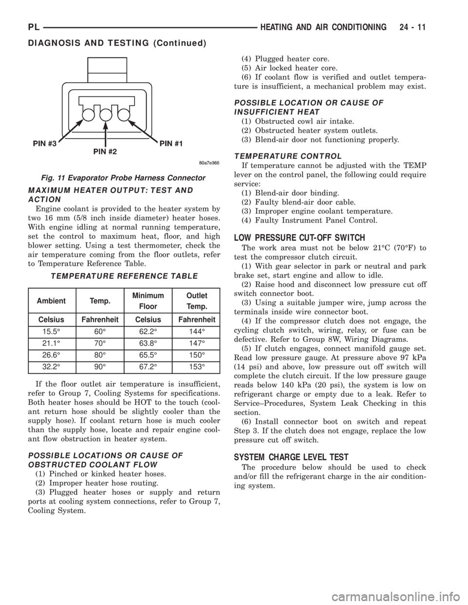
EVAPORATOR PROBE TEST
The work area and vehicle must be between 16É C
(60É F) and 32É C (90É F) when testing the switch.(1) Disconnect the three wire connector from the
evaporator probe lead located behind the glove box.
(2) Start engine and set A/C to low blower motor
speed, panel, full cool, and RECIRC.
(3) Using a voltmeter, check for battery voltage
between Pin 1 and 2. If no voltage is detected, there
is no power to the switch. Check wiring and fuses.
Refer to Group 8W, Wiring Diagrams for circuit diag-
nosis.
(4) Using a voltmeter, check for battery voltage
between Pin 1 and Pin 3. If no voltage is detected,
there is no voltage from the Powertrain Control Mod-
ule. Refer to Group 8W, Wiring Diagrams. If voltage
is OK, connect a jumper wire between Pin 1 and Pin
3. The compressor clutch should engage. If the clutch
engages, remove the jumper wire immediately and go
to Step 5. If the compressor clutch does not engage,
check the operation of the clutch and repair as nec-
essary.
(5) If compressor clutch engages, connect the evap-
orator probe 3-way connector. The compressor clutch
should engage or cycle depending on evaporator tem-
perature. If OK, go to Step 6. If not OK, replace the
clutch cycling switch.
(6) The engine running and the A/C set to:
²Blower motor on low speed
²Panel position
²Full cool
²RECIRC.
Close all doors and windows. Place a thermometer
in the center discharge vent.
(7) If the clutch does not begin to cycle off between
2É C to 7É C (35É F to 45É F), verify that the evapo-
rator probe is fully installed and not loose in evapo-
rator. If it is not properly installed, install probe and
retest outlet temperature. If the evaporator probe is
properly installed, replace the clutch cycling switch.
HEATER PERFORMANCE TEST
PRE-DIAGNOSTIC PREPARATIONS
Review Safety Precautions and Warnings in this
group before performing the following procedures.
Check the coolant level, drive belt tension, vacuum
line connections, radiator air flow and fan operation.
Start engine and allow to warm up to normal tem-
perature.
WARNING: DO NOT REMOVE RADIATOR CAP
WHEN ENGINE IS HOT, PERSONAL INJURY CAN
RESULT.
If vehicle has been run recently, wait 15 minutes
before removing cap. Place a rag over the cap and
turn it to the first safety stop. Allow pressure to
escape through the overflow tube. When the system
stabilizes, remove the cap completely.
24 - 8 HEATING AND AIR CONDITIONINGPL
DIAGNOSIS AND TESTING (Continued)
Page 1144 of 1200
MAXIMUM HEATER OUTPUT: TEST AND
ACTION
Engine coolant is provided to the heater system by
two 16 mm (5/8 inch inside diameter) heater hoses.
With engine idling at normal running temperature,
set the control to maximum heat, floor, and high
blower setting. Using a test thermometer, check the
air temperature coming from the floor outlets, refer
to Temperature Reference Table.
If the floor outlet air temperature is insufficient,
refer to Group 7, Cooling Systems for specifications.
Both heater hoses should be HOT to the touch (cool-
ant return hose should be slightly cooler than the
supply hose). If coolant return hose is much cooler
than the supply hose, locate and repair engine cool-
ant flow obstruction in heater system.
POSSIBLE LOCATIONS OR CAUSE OF
OBSTRUCTED COOLANT FLOW
(1) Pinched or kinked heater hoses.
(2) Improper heater hose routing.
(3) Plugged heater hoses or supply and return
ports at cooling system connections, refer to Group 7,
Cooling System.(4) Plugged heater core.
(5) Air locked heater core.
(6) If coolant flow is verified and outlet tempera-
ture is insufficient, a mechanical problem may exist.
POSSIBLE LOCATION OR CAUSE OF
INSUFFICIENT HEAT
(1) Obstructed cowl air intake.
(2) Obstructed heater system outlets.
(3) Blend-air door not functioning properly.
TEMPERATURE CONTROL
If temperature cannot be adjusted with the TEMP
lever on the control panel, the following could require
service:
(1) Blend-air door binding.
(2) Faulty blend-air door cable.
(3) Improper engine coolant temperature.
(4) Faulty Instrument Panel Control.
LOW PRESSURE CUT-OFF SWITCH
The work area must not be below 21ÉC (70ÉF) to
test the compressor clutch circuit.
(1) With gear selector in park or neutral and park
brake set, start engine and allow to idle.
(2) Raise hood and disconnect low pressure cut off
switch connector boot.
(3) Using a suitable jumper wire, jump across the
terminals inside wire connector boot.
(4) If the compressor clutch does not engage, the
cycling clutch switch, wiring, relay, or fuse can be
defective. Refer to Group 8W, Wiring Diagrams.
(5) If clutch engages, connect manifold gauge set.
Read low pressure gauge. At pressure above 97 kPa
(14 psi) and above, low pressure out off switch will
complete the clutch circuit. If the low pressure gauge
reads below 140 kPa (20 psi), the system is low on
refrigerant charge or empty due to a leak. Refer to
Service±Procedures, System Leak Checking in this
section.
(6) Install connector boot on switch and repeat
Step 3. If the clutch does not engage, replace the low
pressure cut off switch.
SYSTEM CHARGE LEVEL TEST
The procedure below should be used to check
and/or fill the refrigerant charge in the air condition-
ing system.
Fig. 11 Evaporator Probe Harness Connector
TEMPERATURE REFERENCE TABLE
Ambient Temp.Minimum
FloorOutlet
Temp.
Celsius Fahrenheit Celsius Fahrenheit
15.5É 60É 62.2É 144É
21.1É 70É 63.8É 147É
26.6É 80É 65.5É 150É
32.2É 90É 67.2É 153É
PLHEATING AND AIR CONDITIONING 24 - 11
DIAGNOSIS AND TESTING (Continued)