1999 DODGE NEON brake fluid
[x] Cancel search: brake fluidPage 125 of 1200
VACUUM BOOSTER
REMOVE
CAUTION: On ABS equipped vehicles, vacuum in
power booster must be pumped down before
removing master cylinder to prevent booster from
sucking in any contamination. This can be done
simply by pumping the brake pedal until a firm
pedal is achieved, with the ignition off.
(1) On ABS equipped vehicles, with engine not
running, pump the brake pedal until a firm pedal is
achieved (4-5 strokes).
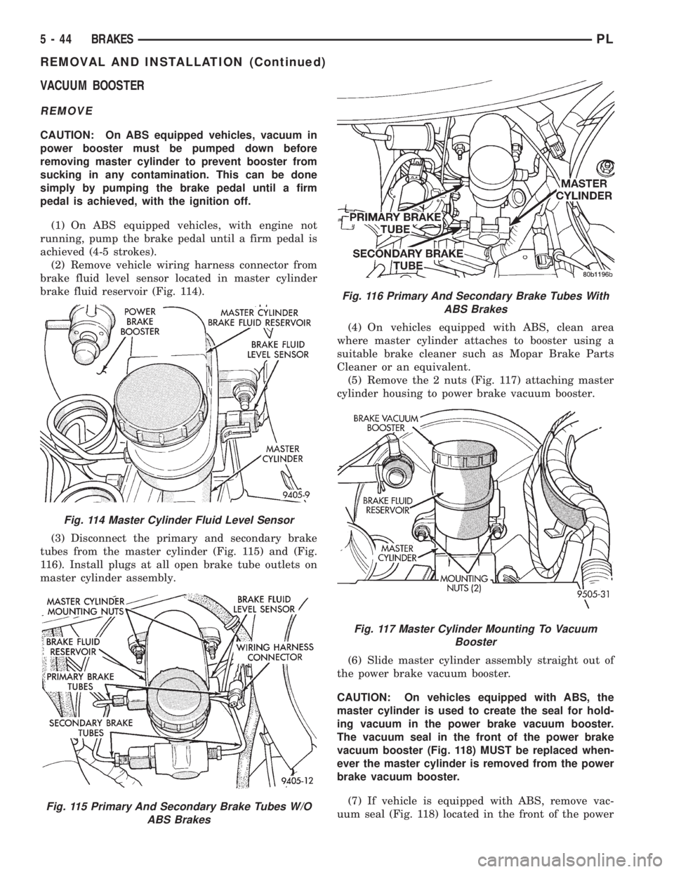
(2) Remove vehicle wiring harness connector from
brake fluid level sensor located in master cylinder
brake fluid reservoir (Fig. 114).
(3) Disconnect the primary and secondary brake
tubes from the master cylinder (Fig. 115) and (Fig.
116). Install plugs at all open brake tube outlets on
master cylinder assembly.(4) On vehicles equipped with ABS, clean area
where master cylinder attaches to booster using a
suitable brake cleaner such as Mopar Brake Parts
Cleaner or an equivalent.
(5) Remove the 2 nuts (Fig. 117) attaching master
cylinder housing to power brake vacuum booster.
(6) Slide master cylinder assembly straight out of
the power brake vacuum booster.
CAUTION: On vehicles equipped with ABS, the
master cylinder is used to create the seal for hold-
ing vacuum in the power brake vacuum booster.
The vacuum seal in the front of the power brake
vacuum booster (Fig. 118) MUST be replaced when-
ever the master cylinder is removed from the power
brake vacuum booster.
(7) If vehicle is equipped with ABS, remove vac-
uum seal (Fig. 118) located in the front of the power
Fig. 114 Master Cylinder Fluid Level Sensor
Fig. 115 Primary And Secondary Brake Tubes W/O
ABS Brakes
Fig. 116 Primary And Secondary Brake Tubes With
ABS Brakes
Fig. 117 Master Cylinder Mounting To Vacuum
Booster
5 - 44 BRAKESPL
REMOVAL AND INSTALLATION (Continued)
Page 128 of 1200
(9) Position master cylinder on studs of power
brake unit, aligning push rod on power brake vac-
uum booster with master cylinder push rod.
(10) Install the 2 master cylinder mounting nuts
(Fig. 117) and torque to 28 N´m (250 in. lbs.) torque.
(11) Connect brake tubes to master cylinder pri-
mary and secondary ports (Fig. 115) and (Fig. 116).
Torque all tube nuts to 17 N´m (145 in. lbs.) torque.
(12) Reconnect wiring connector to fluid level sen-
sor.
(13) Adjust stop lamp switch as necessary.
(14) Bleed brake system.
CHASSIS TUBES AND HOSES
Always use Mopar replacement brake hose assem-
blies to ensure quality, correct length and superior
fatigue life. Care should be taken to make sure that
the tube and hose mating surfaces are clean and free
from nicks and burrs.Hose assemblies for each
brake are unique and not interchangeable.
Use new copper seal washers on all connections
using Banjo Bolts and tighten all fittings to their
specified torques.
The flexible front hydraulic brake hose should
always be installed on the vehicle by first attaching
the Banjo connector to the caliper assembly. Then
bolt the intermediate hose bracket to the strut
assembly allowing the bracket to position the hose to
prevent twisting. Attach the hose to brake tubing,
before attaching to front frame rail. Then tighten all
brake line fittings to specified torque.
On vehicles equipped with rear drum brakes,
install rear brake hoses first to wheel cylinders and
rear struts and then attach hose bracket to body. On
vehicles equipped with rear disc brakes, attach brake
hoses to calipers and struts first and then attach
brake hose bracket to body. Following this procedure
will reduce potential for twisting brake during instal-
lation procedure.
Only double wall 4.75mm (3/16 in.) steel brake line
tubing, with Al- Rich/ZN-AL alloy coating should be
used for replacement. Care must be taken when
replacing brake tubing, to be sure the proper bending
and flaring tools and procedures are used to avoid
kinking. Do not route the tubes against sharp edges,
moving components or into hot areas. All tubes
should be properly attached with recommended
retaining clips.
PROPORTIONING VALVE (BASE BRAKES)
CAUTION: Proportioning valves (Fig. 125) should
never be disassembled.
There are two proportioning valve assemblies used
in each vehicle. Due to different thread sizes, each
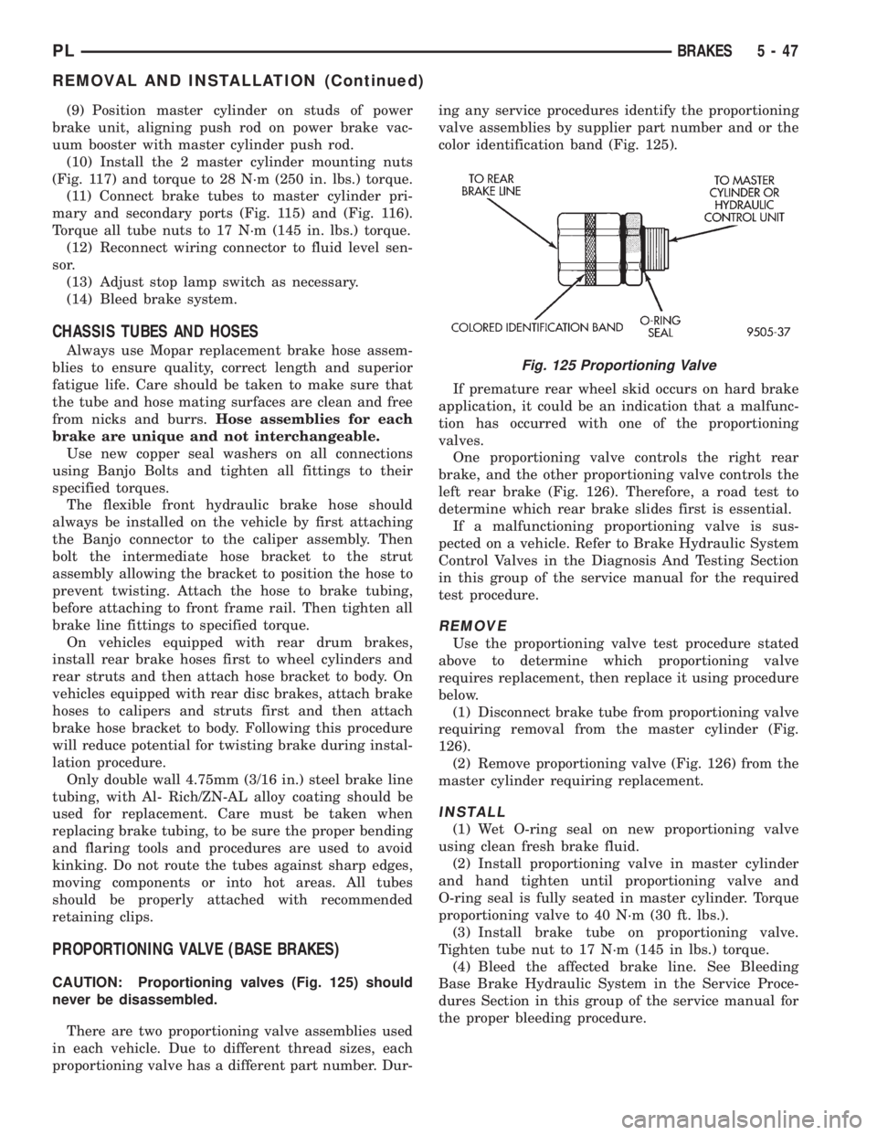
proportioning valve has a different part number. Dur-ing any service procedures identify the proportioning
valve assemblies by supplier part number and or the
color identification band (Fig. 125).
If premature rear wheel skid occurs on hard brake
application, it could be an indication that a malfunc-
tion has occurred with one of the proportioning
valves.
One proportioning valve controls the right rear
brake, and the other proportioning valve controls the
left rear brake (Fig. 126). Therefore, a road test to
determine which rear brake slides first is essential.
If a malfunctioning proportioning valve is sus-
pected on a vehicle. Refer to Brake Hydraulic System
Control Valves in the Diagnosis And Testing Section
in this group of the service manual for the required
test procedure.
REMOVE
Use the proportioning valve test procedure stated
above to determine which proportioning valve
requires replacement, then replace it using procedure
below.
(1) Disconnect brake tube from proportioning valve
requiring removal from the master cylinder (Fig.
126).
(2) Remove proportioning valve (Fig. 126) from the
master cylinder requiring replacement.
INSTALL
(1) Wet O-ring seal on new proportioning valve
using clean fresh brake fluid.
(2) Install proportioning valve in master cylinder
and hand tighten until proportioning valve and
O-ring seal is fully seated in master cylinder. Torque
proportioning valve to 40 N´m (30 ft. lbs.).
(3) Install brake tube on proportioning valve.
Tighten tube nut to 17 N´m (145 in lbs.) torque.
(4) Bleed the affected brake line. See Bleeding
Base Brake Hydraulic System in the Service Proce-
dures Section in this group of the service manual for
the proper bleeding procedure.
Fig. 125 Proportioning Valve
PLBRAKES 5 - 47
REMOVAL AND INSTALLATION (Continued)
Page 138 of 1200
(9) InstallA NEWhub and bearing assembly
retaining nut. Torque the hub and bearing assembly
retaining nut to 168 N´m (124 ft. lbs.).
(10) Install hub and bearing assembly dust cap.
(11) Install rear rotor.
(12) Install rear disc brake caliper on the adapter
(See Brake Shoe Removal).
(13) Install wheel and tire assemblies.
(14) Tighten wheel stud nuts to 129 N´m (95
ft.lbs.).
STOP LAMP SWITCH
REMOVE
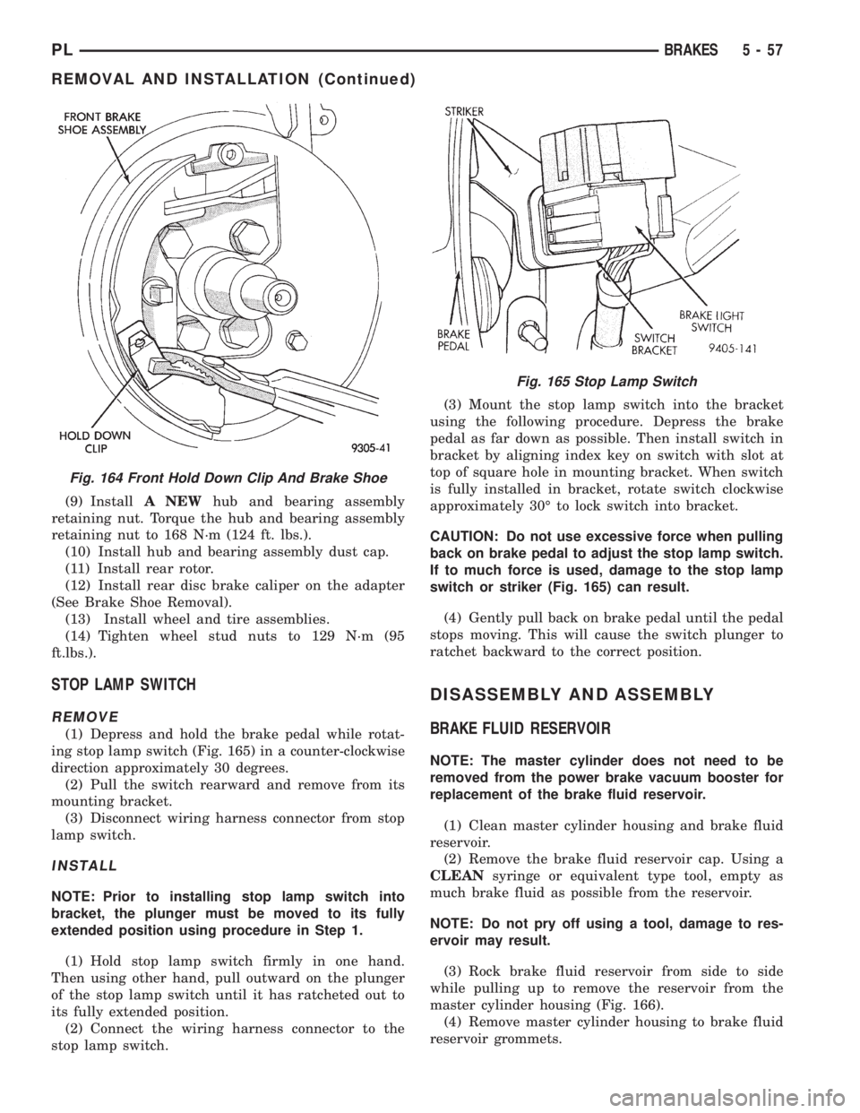
(1) Depress and hold the brake pedal while rotat-
ing stop lamp switch (Fig. 165) in a counter-clockwise
direction approximately 30 degrees.
(2) Pull the switch rearward and remove from its
mounting bracket.
(3) Disconnect wiring harness connector from stop
lamp switch.
INSTALL
NOTE: Prior to installing stop lamp switch into
bracket, the plunger must be moved to its fully
extended position using procedure in Step 1.
(1) Hold stop lamp switch firmly in one hand.
Then using other hand, pull outward on the plunger
of the stop lamp switch until it has ratcheted out to
its fully extended position.
(2) Connect the wiring harness connector to the
stop lamp switch.(3) Mount the stop lamp switch into the bracket
using the following procedure. Depress the brake
pedal as far down as possible. Then install switch in
bracket by aligning index key on switch with slot at
top of square hole in mounting bracket. When switch
is fully installed in bracket, rotate switch clockwise
approximately 30É to lock switch into bracket.
CAUTION: Do not use excessive force when pulling
back on brake pedal to adjust the stop lamp switch.
If to much force is used, damage to the stop lamp
switch or striker (Fig. 165) can result.
(4) Gently pull back on brake pedal until the pedal
stops moving. This will cause the switch plunger to
ratchet backward to the correct position.
DISASSEMBLY AND ASSEMBLY
BRAKE FLUID RESERVOIR
NOTE: The master cylinder does not need to be
removed from the power brake vacuum booster for
replacement of the brake fluid reservoir.
(1) Clean master cylinder housing and brake fluid
reservoir.
(2) Remove the brake fluid reservoir cap. Using a
CLEANsyringe or equivalent type tool, empty as
much brake fluid as possible from the reservoir.
NOTE: Do not pry off using a tool, damage to res-
ervoir may result.
(3) Rock brake fluid reservoir from side to side
while pulling up to remove the reservoir from the
master cylinder housing (Fig. 166).
(4) Remove master cylinder housing to brake fluid
reservoir grommets.
Fig. 164 Front Hold Down Clip And Brake Shoe
Fig. 165 Stop Lamp Switch
PLBRAKES 5 - 57
REMOVAL AND INSTALLATION (Continued)
Page 139 of 1200
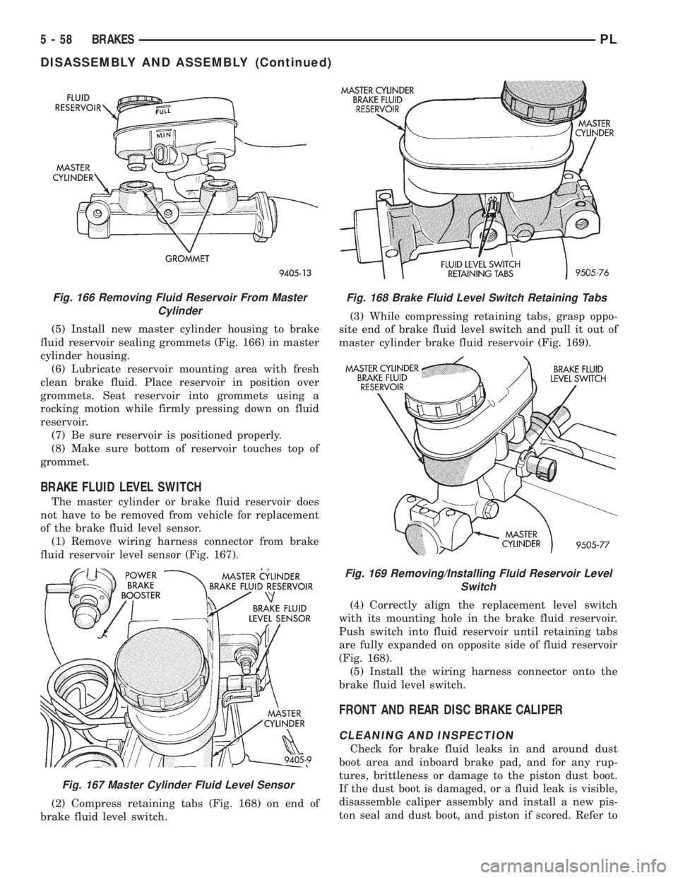
(5) Install new master cylinder housing to brake
fluid reservoir sealing grommets (Fig. 166) in master
cylinder housing.
(6) Lubricate reservoir mounting area with fresh
clean brake fluid. Place reservoir in position over
grommets. Seat reservoir into grommets using a
rocking motion while firmly pressing down on fluid
reservoir.
(7) Be sure reservoir is positioned properly.
(8) Make sure bottom of reservoir touches top of
grommet.
BRAKE FLUID LEVEL SWITCH
The master cylinder or brake fluid reservoir does
not have to be removed from vehicle for replacement
of the brake fluid level sensor.
(1) Remove wiring harness connector from brake
fluid reservoir level sensor (Fig. 167).
(2) Compress retaining tabs (Fig. 168) on end of
brake fluid level switch.(3) While compressing retaining tabs, grasp oppo-
site end of brake fluid level switch and pull it out of
master cylinder brake fluid reservoir (Fig. 169).
(4) Correctly align the replacement level switch
with its mounting hole in the brake fluid reservoir.
Push switch into fluid reservoir until retaining tabs
are fully expanded on opposite side of fluid reservoir
(Fig. 168).
(5) Install the wiring harness connector onto the
brake fluid level switch.
FRONT AND REAR DISC BRAKE CALIPER
CLEANING AND INSPECTION
Check for brake fluid leaks in and around dust
boot area and inboard brake pad, and for any rup-
tures, brittleness or damage to the piston dust boot.
If the dust boot is damaged, or a fluid leak is visible,
disassemble caliper assembly and install a new pis-
ton seal and dust boot, and piston if scored. Refer to
Fig. 166 Removing Fluid Reservoir From Master
Cylinder
Fig. 167 Master Cylinder Fluid Level Sensor
Fig. 168 Brake Fluid Level Switch Retaining Tabs
Fig. 169 Removing/Installing Fluid Reservoir Level
Switch
5 - 58 BRAKESPL
DISASSEMBLY AND ASSEMBLY (Continued)
Page 142 of 1200
from rotor, so hydraulic fluid cannot get on rotor.
Place a small piece of wood between the piston and
caliper fingers.
(2)Carefullydepress brake pedal to hydraulically
push piston out of bore. Then apply and hold down
the brake pedal to any position beyond the first inch
of pedal travel. This will prevent loss of brake fluid
from the master cylinder.
(3) If both front caliper pistons are to be removed,
disconnect brake tube at flexible brake hose at frame
rail. Plug brake tube and remove piston from oppo-
site caliper using the same process as above for the
first piston removal.
(4) Disconnect the brake fluid flex hose from the
caliper assembly.
CAUTION: Do not use excessive force when clamp-
ing caliper in vise. Excessive vise pressure will
cause bore distortion and binding of piston.
(5) To disassemble caliper, mount in a vise
equipped with protective jaws.
(6) Remove guide pin sleeves and guide pin bush-
ings. See Removing Guide Pin Bushings in the cali-
per disassembly section of this manual.
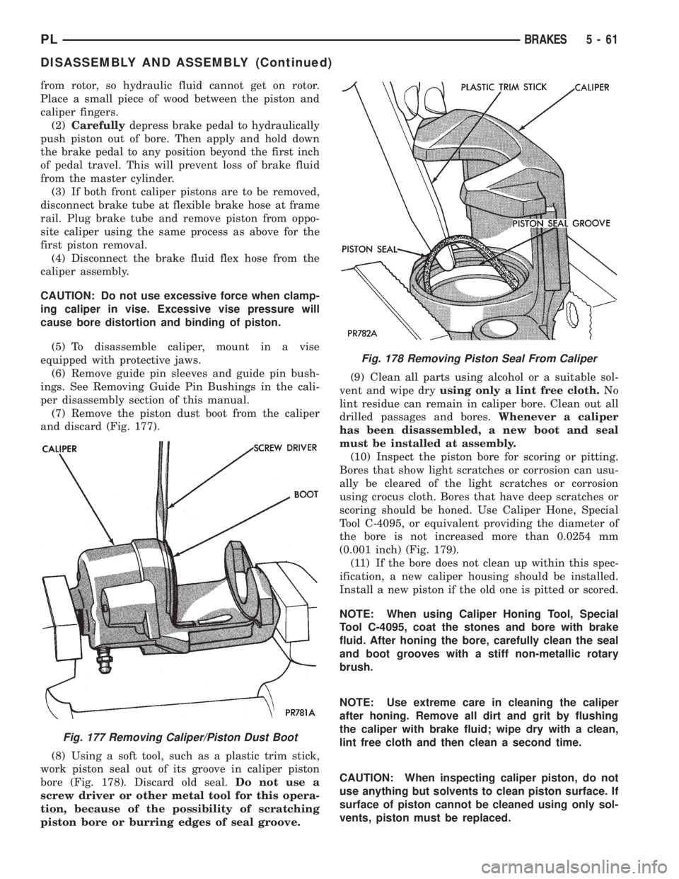
(7) Remove the piston dust boot from the caliper
and discard (Fig. 177).
(8) Using a soft tool, such as a plastic trim stick,
work piston seal out of its groove in caliper piston
bore (Fig. 178). Discard old seal.Do not use a
screw driver or other metal tool for this opera-
tion, because of the possibility of scratching
piston bore or burring edges of seal groove.(9) Clean all parts using alcohol or a suitable sol-
vent and wipe dryusing only a lint free cloth.No
lint residue can remain in caliper bore. Clean out all
drilled passages and bores.Whenever a caliper
has been disassembled, a new boot and seal
must be installed at assembly.
(10) Inspect the piston bore for scoring or pitting.
Bores that show light scratches or corrosion can usu-
ally be cleared of the light scratches or corrosion
using crocus cloth. Bores that have deep scratches or
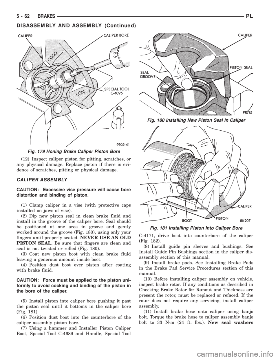
scoring should be honed. Use Caliper Hone, Special
Tool C-4095, or equivalent providing the diameter of
the bore is not increased more than 0.0254 mm
(0.001 inch) (Fig. 179).
(11) If the bore does not clean up within this spec-
ification, a new caliper housing should be installed.
Install a new piston if the old one is pitted or scored.
NOTE: When using Caliper Honing Tool, Special
Tool C-4095, coat the stones and bore with brake
fluid. After honing the bore, carefully clean the seal
and boot grooves with a stiff non-metallic rotary
brush.
NOTE: Use extreme care in cleaning the caliper
after honing. Remove all dirt and grit by flushing
the caliper with brake fluid; wipe dry with a clean,
lint free cloth and then clean a second time.
CAUTION: When inspecting caliper piston, do not
use anything but solvents to clean piston surface. If
surface of piston cannot be cleaned using only sol-
vents, piston must be replaced.
Fig. 177 Removing Caliper/Piston Dust Boot
Fig. 178 Removing Piston Seal From Caliper
PLBRAKES 5 - 61
DISASSEMBLY AND ASSEMBLY (Continued)
Page 143 of 1200
(12) Inspect caliper piston for pitting, scratches, or
any physical damage. Replace piston if there is evi-
dence of scratches, pitting or physical damage.
CALIPER ASSEMBLY
CAUTION: Excessive vise pressure will cause bore
distortion and binding of piston.
(1) Clamp caliper in a vise (with protective caps
installed on jaws of vise).
(2) Dip new piston seal in clean brake fluid and
install in the groove of the caliper bore. Seal should
be positioned at one area in groove and gently
worked around the groove (Fig. 180), using only your
fingers until properly seated.NEVER USE AN OLD
PISTON SEAL.Be sure that fingers are clean and
seal is not twisted or rolled (Fig. 180).
(3) Coat new piston boot with clean brake fluid
leaving a generous amount inside boot.
(4) Position dust boot over piston after coating
with brake fluid.
CAUTION: Force must be applied to the piston uni-
formly to avoid cocking and binding of the piston in
the bore of the caliper.
(5) Install piston into caliper bore pushing it past
the piston seal until it bottoms in the caliper bore
(Fig. 181).
(6) Position dust boot into the counterbore of the
caliper assembly piston bore.
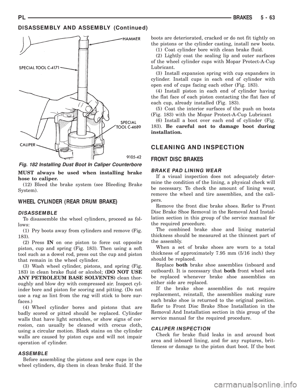
(7) Using a hammer and Installer Piston Caliper
Boot, Special Tool C-4689 and Handle, Special ToolC-4171, drive boot into counterbore of the caliper
(Fig. 182).
(8) Install guide pin sleeves and bushings. See
Install Guide Pin Bushings section in the caliper dis-
assembly section of this manual.
(9) Install brake pads. See Installing Brake Pads
in the Brake Pad Service Procedures section of this
manual.
(10) Before installing caliper assembly on vehicle,
inspect brake rotor. If any conditions as described in
Checking Brake Rotor for Runout and Thickness are
present the rotor, must be replaced or refaced. If the
rotor does not require any servicing, install caliper
assembly.
(11) Install brake hose onto caliper using banjo
bolt. Torque the brake hose to caliper assembly banjo
bolt to 33 N´m (24 ft. lbs.).New seal washers
Fig. 179 Honing Brake Caliper Piston Bore
Fig. 180 Installing New Piston Seal In Caliper
Fig. 181 Installing Piston Into Caliper Bore
5 - 62 BRAKESPL
DISASSEMBLY AND ASSEMBLY (Continued)
Page 144 of 1200
MUST always be used when installing brake
hose to caliper.
(12) Bleed the brake system (see Bleeding Brake
System).
WHEEL CYLINDER (REAR DRUM BRAKE)
DISASSEMBLE
To disassemble the wheel cylinders, proceed as fol-
lows:
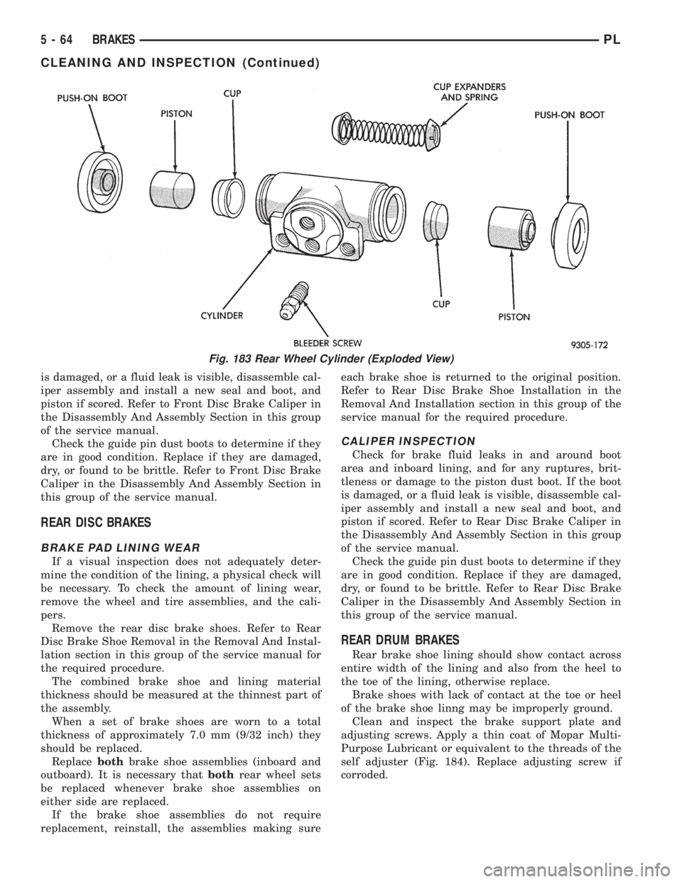
(1) Pry boots away from cylinders and remove (Fig.
183).
(2) PressINon one piston to force out opposite
piston, cup and spring (Fig. 183). Then using a soft
tool such as a dowel rod, press out the cup and piston
that remain in the wheel cylinder.
(3) Wash wheel cylinder, pistons, and spring (Fig.
183) in clean brake fluid or alcohol;(DO NOT USE
ANY PETROLEUM BASE SOLVENTS)clean thor-
oughly and blow dry with compressed air. Inspect cyl-
inder bore and piston for scoring and pitting. (Do not
use a rag as lint from the rag will stick to bore sur-
faces.)
(4) Wheel cylinder bores and pistons that are
badly scored or pitted should be replaced. Cylinder
walls that have light scratches, or show signs of cor-
rosion, can usually be cleaned with crocus cloth,
using a circular motion. Black stains on the cylinder
walls are caused by piston cups and will not impair
operation of cylinder.
ASSEMBLE
Before assembling the pistons and new cups in the
wheel cylinders, dip them in clean brake fluid. If theboots are deteriorated, cracked or do not fit tightly on
the pistons or the cylinder casting, install new boots.
(1) Coat cylinder bore with clean brake fluid.
(2) Lightly coat the sealing lip and outer surfaces
of the wheel cylinder cups with Mopar Protect-A-Cup
Lubricant.
(3) Install expansion spring with cup expanders in
cylinder. Install cups in each end of cylinder with
open end of cups facing each other (Fig. 183).
(4) Install piston in each end of cylinder having
the flat face of each piston contacting the flat face of
each cup, already installed (Fig. 183).
(5) Coat the interior surfaces of the push on boots
(Fig. 183) with the Mopar Protect-A-Cup Lubricant
(6) Install a boot over each end of cylinder (Fig.
183).Be careful not to damage boot during
installation.
CLEANING AND INSPECTION
FRONT DISC BRAKES
BRAKE PAD LINING WEAR
If a visual inspection does not adequately deter-
mine the condition of the lining, a physical check will
be necessary. To check the amount of lining wear,
remove the wheel and tire assemblies, and the cali-
pers.
Remove the front disc brake shoes. Refer to Front
Disc Brake Shoe Removal in the Removal And Instal-
lation section in this group of the service manual for
the required procedure.
The combined brake shoe and lining material
thickness should be measured at the thinnest part of
the assembly.
When a set of brake shoes are worn to a total
thickness of approximately 7.95 mm (5/16 inch) they
should be replaced.
Replacebothbrake shoe assemblies (inboard and
outboard). It is necessary thatbothfront wheel sets
be replaced whenever brake shoe assemblies on
either side are replaced.
If the brake shoe assemblies do not require
replacement, reinstall, the assemblies making sure
each brake shoe is returned to the original position.
Refer to Front Disc Brake Shoe Installation in the
Removal And Installation section in this group of the
service manual for the required procedure.
CALIPER INSPECTION
Check for brake fluid leaks in and around boot
area and inboard lining, and for any ruptures, brit-
tleness or damage to the piston dust boot. If the boot
Fig. 182 Installing Dust Boot In Caliper Counterbore
PLBRAKES 5 - 63
DISASSEMBLY AND ASSEMBLY (Continued)
Page 145 of 1200
is damaged, or a fluid leak is visible, disassemble cal-
iper assembly and install a new seal and boot, and
piston if scored. Refer to Front Disc Brake Caliper in
the Disassembly And Assembly Section in this group
of the service manual.
Check the guide pin dust boots to determine if they
are in good condition. Replace if they are damaged,
dry, or found to be brittle. Refer to Front Disc Brake
Caliper in the Disassembly And Assembly Section in
this group of the service manual.
REAR DISC BRAKES
BRAKE PAD LINING WEAR
If a visual inspection does not adequately deter-
mine the condition of the lining, a physical check will
be necessary. To check the amount of lining wear,
remove the wheel and tire assemblies, and the cali-
pers.
Remove the rear disc brake shoes. Refer to Rear
Disc Brake Shoe Removal in the Removal And Instal-
lation section in this group of the service manual for
the required procedure.
The combined brake shoe and lining material
thickness should be measured at the thinnest part of
the assembly.
When a set of brake shoes are worn to a total
thickness of approximately 7.0 mm (9/32 inch) they
should be replaced.
Replacebothbrake shoe assemblies (inboard and
outboard). It is necessary thatbothrear wheel sets
be replaced whenever brake shoe assemblies on
either side are replaced.
If the brake shoe assemblies do not require
replacement, reinstall, the assemblies making sureeach brake shoe is returned to the original position.
Refer to Rear Disc Brake Shoe Installation in the
Removal And Installation section in this group of the
service manual for the required procedure.
CALIPER INSPECTION
Check for brake fluid leaks in and around boot
area and inboard lining, and for any ruptures, brit-
tleness or damage to the piston dust boot. If the boot
is damaged, or a fluid leak is visible, disassemble cal-
iper assembly and install a new seal and boot, and
piston if scored. Refer to Rear Disc Brake Caliper in
the Disassembly And Assembly Section in this group
of the service manual.
Check the guide pin dust boots to determine if they
are in good condition. Replace if they are damaged,
dry, or found to be brittle. Refer to Rear Disc Brake
Caliper in the Disassembly And Assembly Section in
this group of the service manual.
REAR DRUM BRAKES
Rear brake shoe lining should show contact across
entire width of the lining and also from the heel to
the toe of the lining, otherwise replace.
Brake shoes with lack of contact at the toe or heel
of the brake shoe linng may be improperly ground.
Clean and inspect the brake support plate and
adjusting screws. Apply a thin coat of Mopar Multi-
Purpose Lubricant or equivalent to the threads of the
self adjuster (Fig. 184). Replace adjusting screw if
corroded.
Fig. 183 Rear Wheel Cylinder (Exploded View)
5 - 64 BRAKESPL
CLEANING AND INSPECTION (Continued)