1999 DODGE NEON brake fluid
[x] Cancel search: brake fluidPage 102 of 1200
enough fluid has not passed through the system to
expel all the trapped air. Be sure to monitor the fluid
level in the pressure bleeder. It must stay at the
proper level so air will not be allowed to reenter the
brake system through the master cylinder reservoir.
BLEEDING WITHOUT A PRESSURE BLEEDER
NOTE: Correct bleeding of the brakes hydraulic
system without the use of pressure bleeding equip-
ment will require the aid of a helper.
The following wheel sequence for bleeding the
brake hydraulic system should be used to ensure
adequate removal of all trapped air from the hydrau-
lic system.
²Left rear wheel
²Right front wheel
²Right rear wheel
²Left front wheel
(1) Attach a clear plastic hose to the bleeder screw
starting at the right rear wheel and feed the hose
into a clear jar containing enough fresh brake fluid
to submerge the end of the hose (Fig. 36).
(2) Pump the brake pedal three or four times and
hold it down before the bleeder screw is opened.
(3) Open the bleeder screw at least 1 full turn.
When the bleeder screw opens the brake pedal will
drop.
(4) Close the bleeder screw. Release the brake
pedal onlyafterthe bleeder screw is closed.
(5) Repeat steps 1 through 3, four or five times at
each bleeder screw. Then check the pedal for travel.
If pedal travel is excessive or has not been improved,
enough fluid has not passed through the system to
expel all the trapped air. Be sure to monitor the fluid
level in the master cylinder reservoir. It must stay at
the proper level so air will not be allowed to re-enter
the brake system.(6) Test drive vehicle to be sure brakes are operat-
ing correctly and that pedal is solid.
MASTER CYLINDER BLEEDING
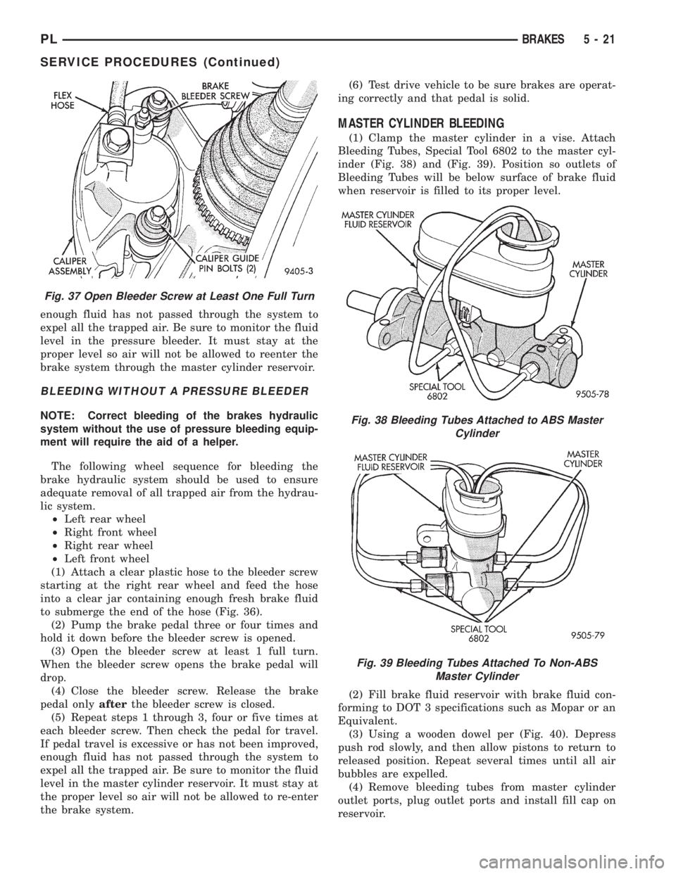
(1) Clamp the master cylinder in a vise. Attach
Bleeding Tubes, Special Tool 6802 to the master cyl-
inder (Fig. 38) and (Fig. 39). Position so outlets of
Bleeding Tubes will be below surface of brake fluid
when reservoir is filled to its proper level.
(2) Fill brake fluid reservoir with brake fluid con-
forming to DOT 3 specifications such as Mopar or an
Equivalent.
(3) Using a wooden dowel per (Fig. 40). Depress
push rod slowly, and then allow pistons to return to
released position. Repeat several times until all air
bubbles are expelled.
(4) Remove bleeding tubes from master cylinder
outlet ports, plug outlet ports and install fill cap on
reservoir.
Fig. 37 Open Bleeder Screw at Least One Full Turn
Fig. 38 Bleeding Tubes Attached to ABS Master
Cylinder
Fig. 39 Bleeding Tubes Attached To Non-ABS
Master Cylinder
PLBRAKES 5 - 21
SERVICE PROCEDURES (Continued)
Page 106 of 1200
released position. Check the rear wheels of the vehi-
cle, they should rotate freely without dragging.
BRAKE TUBE REPAIR
Only double wall 4.75mm (3/16 in.) steel tubing
with Al-rich/ZN-AL alloy coating and the correct tube
nuts are to be used for replacement of a hydraulic
brake tube.
Care should be taken when repairing brake tubing,
to be sure the proper bending and flaring tools and
procedures are used, to avoid kinking. Do not route
the tubes against sharp edges, moving components or
into hot areas. All tubes should be properly attached
with recommended retaining clips.
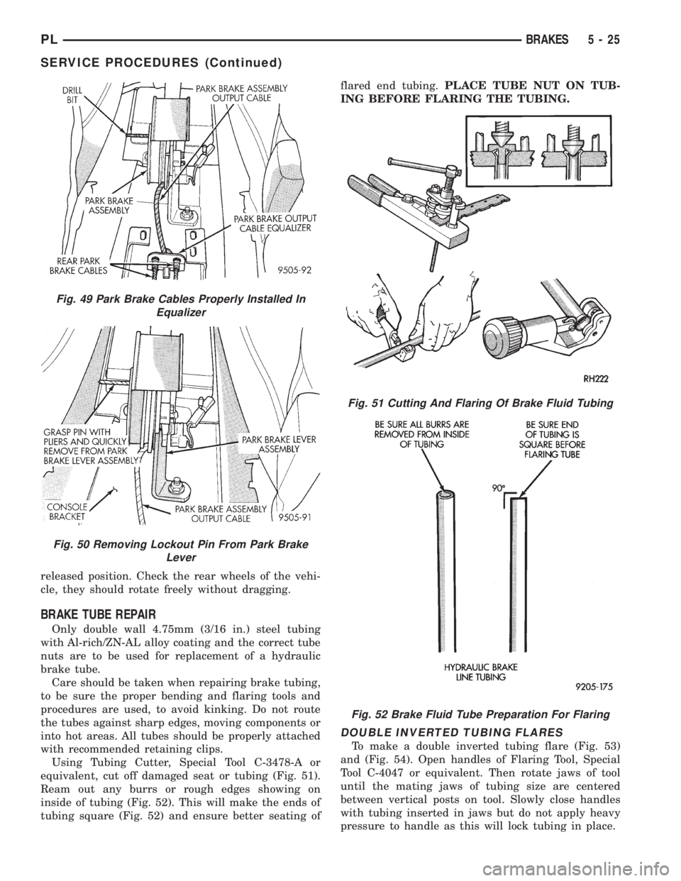
Using Tubing Cutter, Special Tool C-3478-A or
equivalent, cut off damaged seat or tubing (Fig. 51).
Ream out any burrs or rough edges showing on
inside of tubing (Fig. 52). This will make the ends of
tubing square (Fig. 52) and ensure better seating offlared end tubing.PLACE TUBE NUT ON TUB-
ING BEFORE FLARING THE TUBING.
DOUBLE INVERTED TUBING FLARES
To make a double inverted tubing flare (Fig. 53)
and (Fig. 54). Open handles of Flaring Tool, Special
Tool C-4047 or equivalent. Then rotate jaws of tool
until the mating jaws of tubing size are centered
between vertical posts on tool. Slowly close handles
with tubing inserted in jaws but do not apply heavy
pressure to handle as this will lock tubing in place.
Fig. 49 Park Brake Cables Properly Installed In
Equalizer
Fig. 50 Removing Lockout Pin From Park Brake
Lever
Fig. 51 Cutting And Flaring Of Brake Fluid Tubing
Fig. 52 Brake Fluid Tube Preparation For Flaring
PLBRAKES 5 - 25
SERVICE PROCEDURES (Continued)
Page 110 of 1200
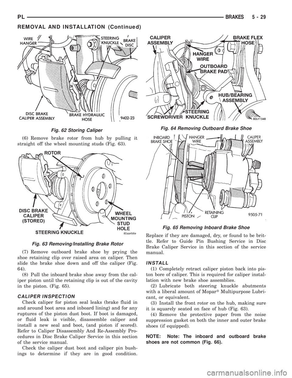
(6) Remove brake rotor from hub by pulling it
straight off the wheel mounting studs (Fig. 63).
(7) Remove outboard brake shoe by prying the
shoe retaining clip over raised area on caliper. Then
slide the brake shoe down and off the caliper (Fig.
64).
(8) Pull the inboard brake shoe away from the cal-
iper piston until the retaining clip is out of the cavity
in the piston. (Fig. 65).
CALIPER INSPECTION
Check caliper for piston seal leaks (brake fluid in
and around boot area and inboard lining) and for any
ruptures of the piston dust boot. If boot is damaged,
or fluid leak is visible, disassemble caliper and
install a new seal and boot, (and piston if scored).
Refer to Caliper Disassembly And Re-Assembly Pro-
cedures in Disc Brake Caliper Service in this section
of the service manual.
Check the caliper dust boot and caliper pin bush-
ings to determine if they are in good condition.Replace if they are damaged, dry, or found to be brit-
tle. Refer to Guide Pin Bushing Service in Disc
Brake Caliper Service in this section of the service
manual.
INSTALL
(1) Completely retract caliper piston back into pis-
ton bore of caliper. This is required for caliper instal-
lation with new brake shoe assemblies.
(2) Lubricate both steering knuckle abutments
with a liberal amount of MopartMultipurpose Lubri-
cant, or equivalent.
(3) Install the front rotor on the hub, making sure
it is squarely seated on face of hub (Fig. 63).
(4) Remove the protective paper from the noise
suppression gasket on both the inner and outer brake
shoes (if equipped).
NOTE: Note: The inboard and outboard brake
shoes are not common (Fig. 66).
Fig. 62 Storing Caliper
Fig. 63 Removing/Installing Brake Rotor
Fig. 64 Removing Outboard Brake Shoe
Fig. 65 Removing Inboard Brake Shoe
PLBRAKES 5 - 29
REMOVAL AND INSTALLATION (Continued)
Page 114 of 1200
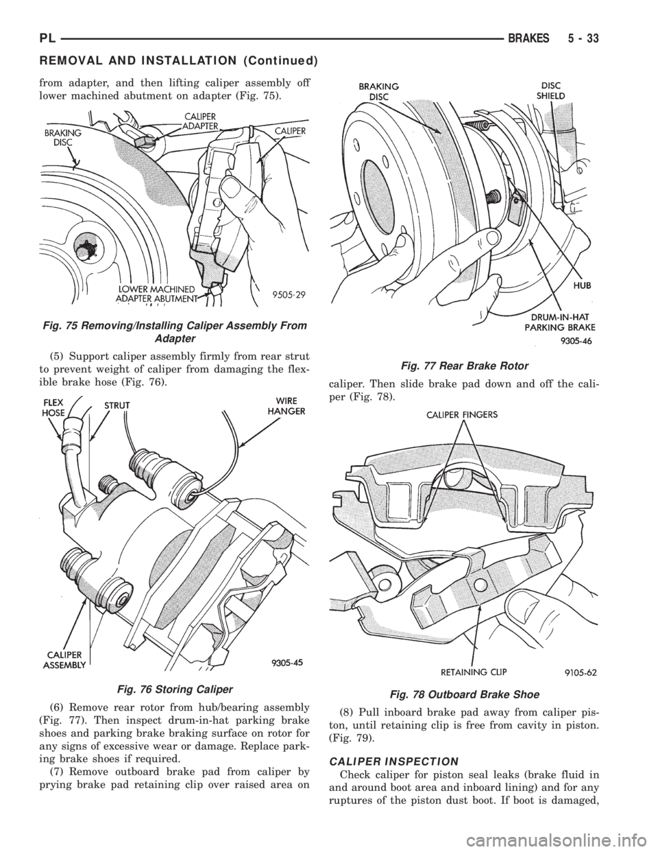
from adapter, and then lifting caliper assembly off
lower machined abutment on adapter (Fig. 75).
(5) Support caliper assembly firmly from rear strut
to prevent weight of caliper from damaging the flex-
ible brake hose (Fig. 76).
(6) Remove rear rotor from hub/bearing assembly
(Fig. 77). Then inspect drum-in-hat parking brake
shoes and parking brake braking surface on rotor for
any signs of excessive wear or damage. Replace park-
ing brake shoes if required.
(7) Remove outboard brake pad from caliper by
prying brake pad retaining clip over raised area oncaliper. Then slide brake pad down and off the cali-
per (Fig. 78).
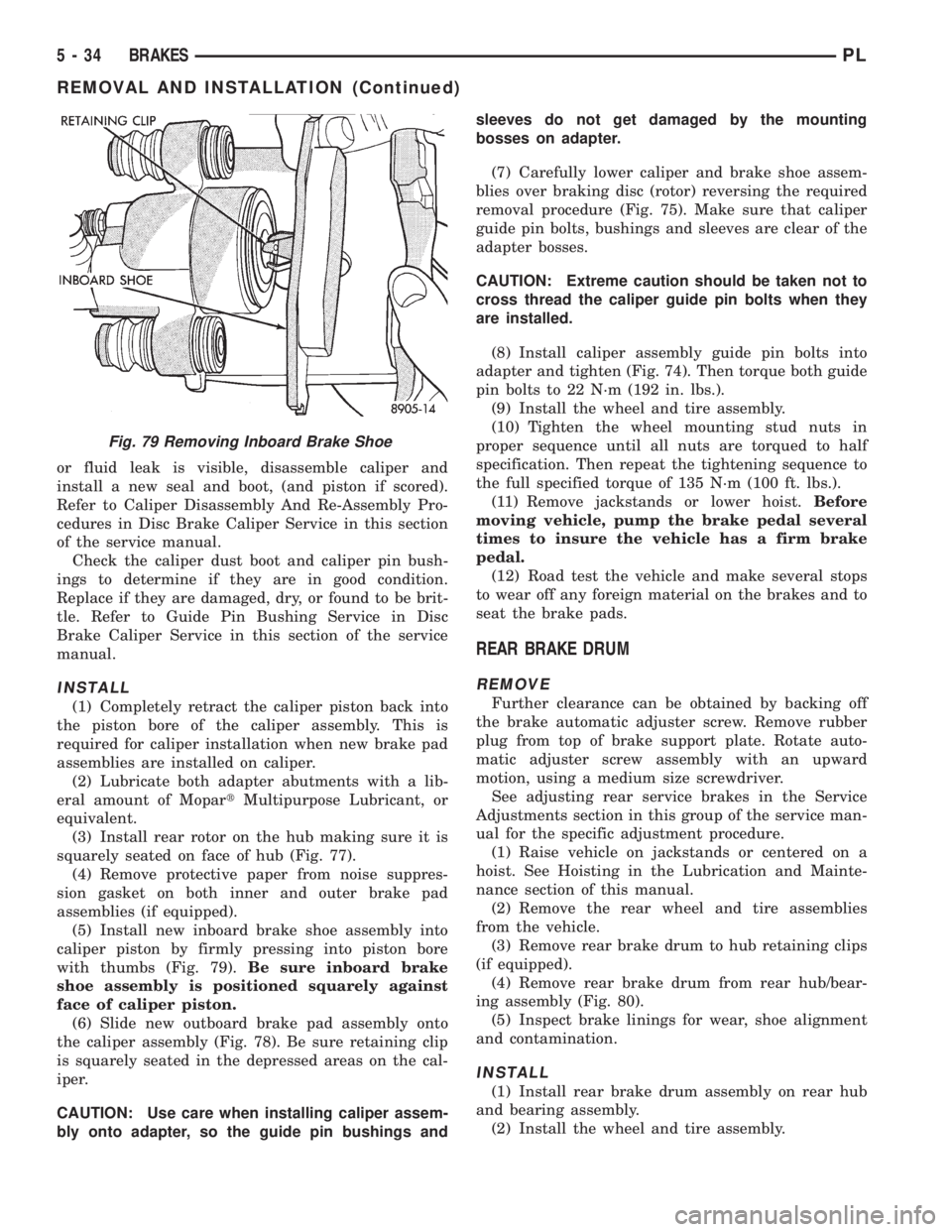
(8) Pull inboard brake pad away from caliper pis-
ton, until retaining clip is free from cavity in piston.
(Fig. 79).
CALIPER INSPECTION
Check caliper for piston seal leaks (brake fluid in
and around boot area and inboard lining) and for any
ruptures of the piston dust boot. If boot is damaged,
Fig. 75 Removing/Installing Caliper Assembly From
Adapter
Fig. 76 Storing Caliper
Fig. 77 Rear Brake Rotor
Fig. 78 Outboard Brake Shoe
PLBRAKES 5 - 33
REMOVAL AND INSTALLATION (Continued)
Page 115 of 1200
or fluid leak is visible, disassemble caliper and
install a new seal and boot, (and piston if scored).
Refer to Caliper Disassembly And Re-Assembly Pro-
cedures in Disc Brake Caliper Service in this section
of the service manual.
Check the caliper dust boot and caliper pin bush-
ings to determine if they are in good condition.
Replace if they are damaged, dry, or found to be brit-
tle. Refer to Guide Pin Bushing Service in Disc
Brake Caliper Service in this section of the service
manual.
INSTALL
(1) Completely retract the caliper piston back into
the piston bore of the caliper assembly. This is
required for caliper installation when new brake pad
assemblies are installed on caliper.
(2) Lubricate both adapter abutments with a lib-
eral amount of MopartMultipurpose Lubricant, or
equivalent.
(3) Install rear rotor on the hub making sure it is
squarely seated on face of hub (Fig. 77).
(4) Remove protective paper from noise suppres-
sion gasket on both inner and outer brake pad
assemblies (if equipped).
(5) Install new inboard brake shoe assembly into
caliper piston by firmly pressing into piston bore
with thumbs (Fig. 79).Be sure inboard brake
shoe assembly is positioned squarely against
face of caliper piston.
(6) Slide new outboard brake pad assembly onto
the caliper assembly (Fig. 78). Be sure retaining clip
is squarely seated in the depressed areas on the cal-
iper.
CAUTION: Use care when installing caliper assem-
bly onto adapter, so the guide pin bushings andsleeves do not get damaged by the mounting
bosses on adapter.
(7) Carefully lower caliper and brake shoe assem-
blies over braking disc (rotor) reversing the required
removal procedure (Fig. 75). Make sure that caliper
guide pin bolts, bushings and sleeves are clear of the
adapter bosses.
CAUTION: Extreme caution should be taken not to
cross thread the caliper guide pin bolts when they
are installed.
(8) Install caliper assembly guide pin bolts into
adapter and tighten (Fig. 74). Then torque both guide
pin bolts to 22 N´m (192 in. lbs.).
(9) Install the wheel and tire assembly.
(10) Tighten the wheel mounting stud nuts in
proper sequence until all nuts are torqued to half
specification. Then repeat the tightening sequence to
the full specified torque of 135 N´m (100 ft. lbs.).
(11) Remove jackstands or lower hoist.Before
moving vehicle, pump the brake pedal several
times to insure the vehicle has a firm brake
pedal.
(12) Road test the vehicle and make several stops
to wear off any foreign material on the brakes and to
seat the brake pads.
REAR BRAKE DRUM
REMOVE
Further clearance can be obtained by backing off
the brake automatic adjuster screw. Remove rubber
plug from top of brake support plate. Rotate auto-
matic adjuster screw assembly with an upward
motion, using a medium size screwdriver.
See adjusting rear service brakes in the Service
Adjustments section in this group of the service man-
ual for the specific adjustment procedure.
(1) Raise vehicle on jackstands or centered on a
hoist. See Hoisting in the Lubrication and Mainte-
nance section of this manual.
(2) Remove the rear wheel and tire assemblies
from the vehicle.
(3) Remove rear brake drum to hub retaining clips
(if equipped).
(4) Remove rear brake drum from rear hub/bear-
ing assembly (Fig. 80).
(5) Inspect brake linings for wear, shoe alignment
and contamination.
INSTALL
(1) Install rear brake drum assembly on rear hub
and bearing assembly.
(2) Install the wheel and tire assembly.
Fig. 79 Removing Inboard Brake Shoe
5 - 34 BRAKESPL
REMOVAL AND INSTALLATION (Continued)
Page 120 of 1200
the required lifting procedure to be used for this
vehicle.
(2) Remove the tire and wheel assembly from the
vehicle.
(3) Remove rear brake drum.
(4) Remove rear brake shoe assemblies from the
brake support plate. Refer to Rear Brake Shoes in
the Removal And Installation Section in this group of
the service manual for the proper brake shoe assem-
bly removal procedure.
(5) If brake shoes are wet with grease or brake
fluid, remove and replace.
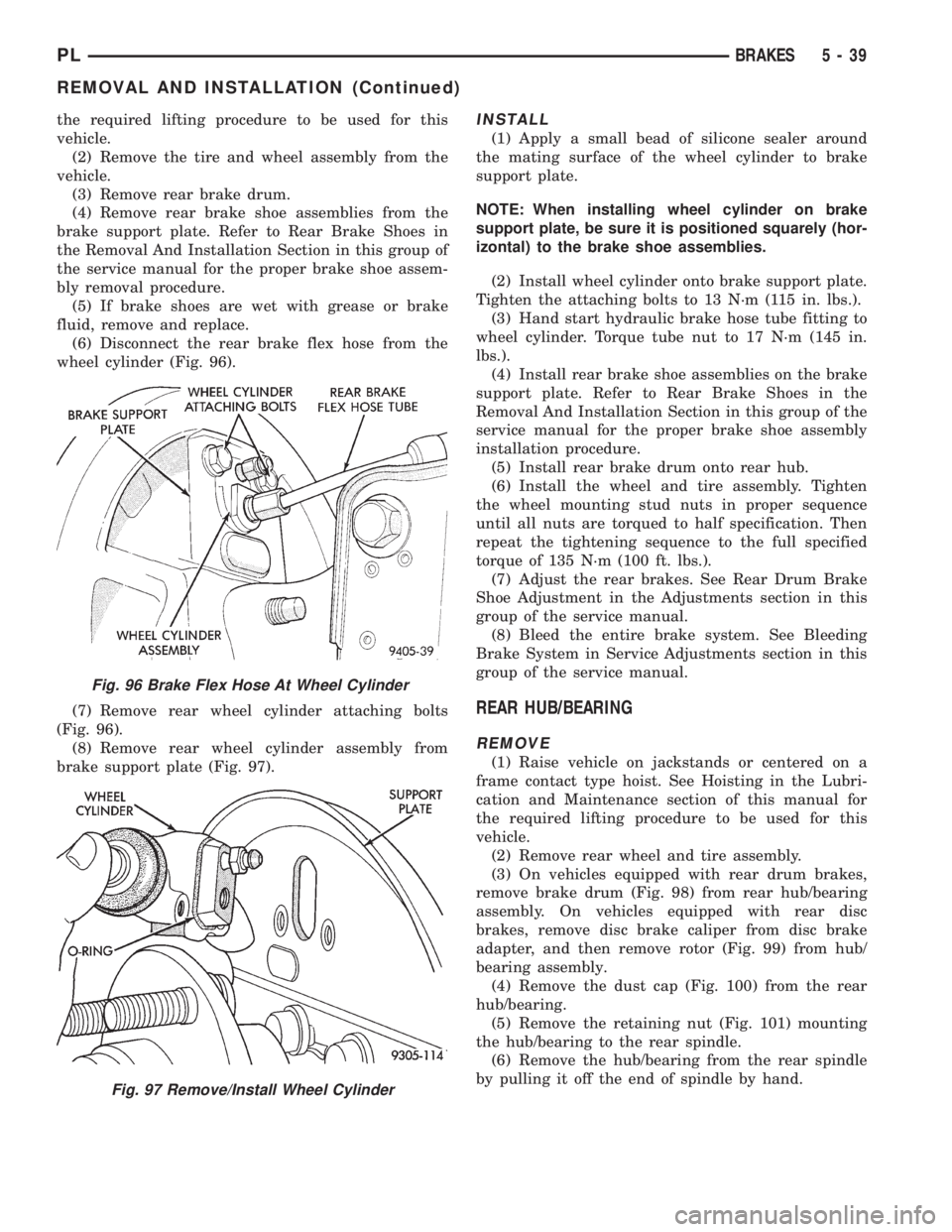
(6) Disconnect the rear brake flex hose from the
wheel cylinder (Fig. 96).
(7) Remove rear wheel cylinder attaching bolts
(Fig. 96).
(8) Remove rear wheel cylinder assembly from
brake support plate (Fig. 97).INSTALL
(1) Apply a small bead of silicone sealer around
the mating surface of the wheel cylinder to brake
support plate.
NOTE: When installing wheel cylinder on brake
support plate, be sure it is positioned squarely (hor-
izontal) to the brake shoe assemblies.
(2) Install wheel cylinder onto brake support plate.
Tighten the attaching bolts to 13 N´m (115 in. lbs.).
(3) Hand start hydraulic brake hose tube fitting to
wheel cylinder. Torque tube nut to 17 N´m (145 in.
lbs.).
(4) Install rear brake shoe assemblies on the brake
support plate. Refer to Rear Brake Shoes in the
Removal And Installation Section in this group of the
service manual for the proper brake shoe assembly
installation procedure.
(5) Install rear brake drum onto rear hub.
(6) Install the wheel and tire assembly. Tighten
the wheel mounting stud nuts in proper sequence
until all nuts are torqued to half specification. Then
repeat the tightening sequence to the full specified
torque of 135 N´m (100 ft. lbs.).
(7) Adjust the rear brakes. See Rear Drum Brake
Shoe Adjustment in the Adjustments section in this
group of the service manual.
(8) Bleed the entire brake system. See Bleeding
Brake System in Service Adjustments section in this
group of the service manual.
REAR HUB/BEARING
REMOVE
(1) Raise vehicle on jackstands or centered on a
frame contact type hoist. See Hoisting in the Lubri-
cation and Maintenance section of this manual for
the required lifting procedure to be used for this
vehicle.
(2) Remove rear wheel and tire assembly.
(3) On vehicles equipped with rear drum brakes,
remove brake drum (Fig. 98) from rear hub/bearing
assembly. On vehicles equipped with rear disc
brakes, remove disc brake caliper from disc brake
adapter, and then remove rotor (Fig. 99) from hub/
bearing assembly.
(4) Remove the dust cap (Fig. 100) from the rear
hub/bearing.
(5) Remove the retaining nut (Fig. 101) mounting
the hub/bearing to the rear spindle.
(6) Remove the hub/bearing from the rear spindle
by pulling it off the end of spindle by hand.
Fig. 96 Brake Flex Hose At Wheel Cylinder
Fig. 97 Remove/Install Wheel Cylinder
PLBRAKES 5 - 39
REMOVAL AND INSTALLATION (Continued)
Page 122 of 1200
MASTER CYLINDER
REMOVE
CAUTION: On ABS equipped vehicles, vacuum in
power booster must be pumped down before
removing master cylinder to prevent booster from
sucking in any contamination. This can be done
simply by pumping the brake pedal until a firm
pedal is achieved, with the ignition off.
(1) On ABS equipped vehicles, be sure engine is
not running, and pump the brake pedal until a firm
pedal is achieved (4-5 strokes).
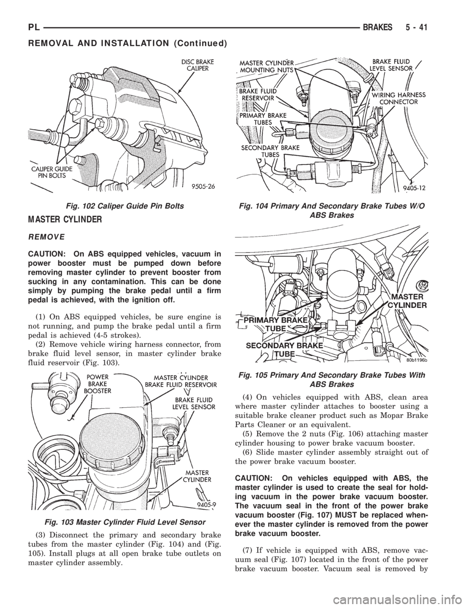
(2) Remove vehicle wiring harness connector, from
brake fluid level sensor, in master cylinder brake
fluid reservoir (Fig. 103).
(3) Disconnect the primary and secondary brake
tubes from the master cylinder (Fig. 104) and (Fig.
105). Install plugs at all open brake tube outlets on
master cylinder assembly.(4) On vehicles equipped with ABS, clean area
where master cylinder attaches to booster using a
suitable brake cleaner product such as Mopar Brake
Parts Cleaner or an equivalent.
(5) Remove the 2 nuts (Fig. 106) attaching master
cylinder housing to power brake vacuum booster.
(6) Slide master cylinder assembly straight out of
the power brake vacuum booster.
CAUTION: On vehicles equipped with ABS, the
master cylinder is used to create the seal for hold-
ing vacuum in the power brake vacuum booster.
The vacuum seal in the front of the power brake
vacuum booster (Fig. 107) MUST be replaced when-
ever the master cylinder is removed from the power
brake vacuum booster.
(7) If vehicle is equipped with ABS, remove vac-
uum seal (Fig. 107) located in the front of the power
brake vacuum booster. Vacuum seal is removed by
Fig. 102 Caliper Guide Pin Bolts
Fig. 103 Master Cylinder Fluid Level Sensor
Fig. 104 Primary And Secondary Brake Tubes W/O
ABS Brakes
Fig. 105 Primary And Secondary Brake Tubes With
ABS Brakes
PLBRAKES 5 - 41
REMOVAL AND INSTALLATION (Continued)
Page 123 of 1200
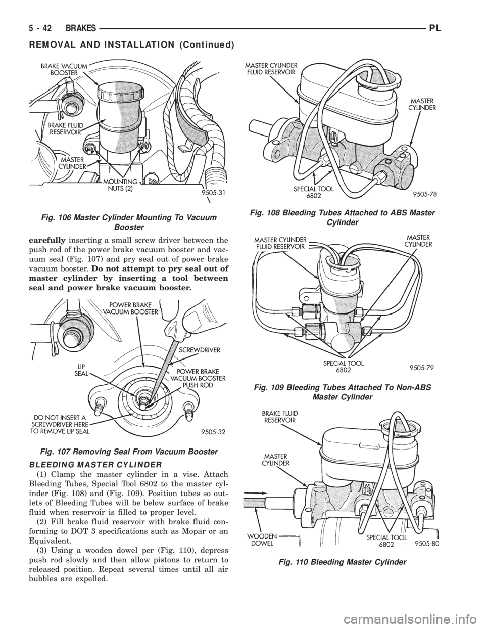
carefullyinserting a small screw driver between the
push rod of the power brake vacuum booster and vac-
uum seal (Fig. 107) and pry seal out of power brake
vacuum booster.Do not attempt to pry seal out of
master cylinder by inserting a tool between
seal and power brake vacuum booster.
BLEEDING MASTER CYLINDER
(1) Clamp the master cylinder in a vise. Attach
Bleeding Tubes, Special Tool 6802 to the master cyl-
inder (Fig. 108) and (Fig. 109). Position tubes so out-
lets of Bleeding Tubes will be below surface of brake
fluid when reservoir is filled to proper level.
(2) Fill brake fluid reservoir with brake fluid con-
forming to DOT 3 specifications such as Mopar or an
Equivalent.
(3) Using a wooden dowel per (Fig. 110), depress
push rod slowly and then allow pistons to return to
released position. Repeat several times until all air
bubbles are expelled.
Fig. 106 Master Cylinder Mounting To Vacuum
Booster
Fig. 107 Removing Seal From Vacuum Booster
Fig. 108 Bleeding Tubes Attached to ABS Master
Cylinder
Fig. 109 Bleeding Tubes Attached To Non-ABS
Master Cylinder
Fig. 110 Bleeding Master Cylinder
5 - 42 BRAKESPL
REMOVAL AND INSTALLATION (Continued)