1999 DODGE NEON brake fluid
[x] Cancel search: brake fluidPage 83 of 1200
BASE BRAKE SYSTEM
INDEX
page page
DESCRIPTION AND OPERATION
CHASSIS TUBES AND HOSES.............. 6
FRONT DISC BRAKES..................... 2
MASTER CYLINDER...................... 6
PARKING BRAKES........................ 4
PROPORTIONING VALVES................. 5
REAR DISC BRAKES...................... 4
REAR DRUM BRAKES..................... 4
REAR WHEEL HUB/BEARING............... 8
RED BRAKE WARNING LAMP............... 7
STOP LAMP SWITCH...................... 8
VACUUM BOOSTER...................... 6
DIAGNOSIS AND TESTING
BRAKE FLUID CONTAMINATION............ 19
BRAKE SYSTEM BASIC DIAGNOSIS GUIDE.... 9
BRAKE SYSTEM DIAGNOSIS CHARTS....... 10
DRUM BRAKE AUTOMATIC ADJUSTER....... 14
PROPORTIONING VALVES................ 16
RED BRAKE WARNING LAMP TEST......... 19
ROTOR THICKNESS AND RUNOUT.......... 14
STOP LAMP SWITCH TEST PROCEDURE..... 19
SERVICE PROCEDURES
BRAKE BLEEDING....................... 20
BRAKE DRUM MACHINING................ 23
BRAKE FLUID LEVEL CHECK.............. 19
BRAKE ROTOR MACHINING............... 22
BRAKE TUBE REPAIR.................... 25
MASTER CYLINDER BLEEDING............ 21
PARK BRAKE LEVER AUTO ADJUSTER
MECHANISM.......................... 23
REMOVAL AND INSTALLATION
CHASSIS TUBES AND HOSES.............. 47
FRONT DISC BRAKE CALIPER............. 26
FRONT DISC BRAKE SHOES.............. 28
MASTER CYLINDER..................... 41
PARK BRAKE CABLES.................... 50
PARK BRAKE LEVER ASSEMBLY........... 48PARK BRAKE LEVER OUTPUT CABLE....... 49
PARK BRAKE SHOES WITH REAR DISC
BRAKES............................. 55
PROPORTIONING VALVE (BASE BRAKES).... 47
REAR BRAKE DRUM..................... 34
REAR BRAKE SHOE SUPPORT PLATE....... 37
REAR BRAKE SHOES.................... 35
REAR BRAKE WHEEL CYLINDER........... 38
REAR DISC BRAKE CALIPER.............. 30
REAR DISC BRAKE SHOES................ 32
REAR HUB/BEARING..................... 39
STOP LAMP SWITCH..................... 57
VACUUM BOOSTER..................... 44
WHEEL AND TIRE ASSEMBLY.............. 26
DISASSEMBLY AND ASSEMBLY
BRAKE FLUID LEVEL SWITCH............. 58
BRAKE FLUID RESERVOIR................ 57
FRONT AND REAR DISC BRAKE CALIPER.... 58
WHEEL CYLINDER (REAR DRUM BRAKE).... 63
CLEANING AND INSPECTION
CHASSIS TUBES AND HOSES.............. 65
FRONT DISC BRAKES.................... 63
REAR DISC BRAKES..................... 64
REAR DRUM BRAKE WHEEL CYLINDER...... 65
REAR DRUM BRAKES.................... 64
REAR WHEEL HUB AND BEARING ASSEMBLY . 65
ADJUSTMENTS
PARK BRAKE ADJUSTMENT............... 66
REAR DRUM BRAKE SHOE ADJUSTMENT.... 65
STOP LAMP SWITCH..................... 65
SPECIFICATIONS
BRAKE ACTUATION SYSTEM.............. 67
BRAKE FASTENER TORQUE SPECIFICATIONS . 67
BRAKE FLUID.......................... 67
SPECIAL TOOLS
BASE BRAKE SYSTEM................... 68
DESCRIPTION AND OPERATION
FRONT DISC BRAKES
The front disc brakes (Fig. 1) and (Fig. 2) consists
of the following components:
²The driving hub
²Braking disc (rotor)
²Caliper assembly - single piston, floating type
²Brake shoes and linings
The double pin calipers are mounted directly to the
steering knuckles and use no adapter. The caliper ismounted to the steering knuckle using bushings,
sleeves and 2 guide pin bolts which thread directly
into bosses on the steering knuckle (Fig. 2) and (Fig.
3).
Two machined abutments on the steering knuckle
position the caliper. The guide pin bolts, sleeves and
bushings control the side to side movement of the
caliper. The piston seal is designed to pull the piston
back into the bore of the caliper when the brake
pedal is released. This maintains the proper brake
shoe to rotor clearance (Fig. 4).
5 - 2 BRAKESPL
Page 84 of 1200

All the front brake forces generated during braking
of the vehicle is taken up directly by the steering
knuckles of the vehicle.
The caliper is a one piece casting with the inboard
side containing a single piston cylinder bore.
The front disc brake caliper piston (Fig. 2), is man-
ufactured from a phenolic compound. The outside
diameter of the caliper piston is 54 mm.
A square cut rubber piston seal is located in a
machined groove in the caliper cylinder bore. This
provides a hydraulic seal between the piston and the
cylinder wall (Fig. 4).
A rubber dust boot is installed in the cylinder bore
opening and in a groove in the piston (Fig. 4). This
prevents contamination in the bore area.As front disc brake linings wear, master cylinder
reservoir brake fluid level will drop. Fluid level
should be checked after replacing linings.
Front disc brakes are equipped with an audible
wear indicator (Fig. 2) on the outboard brake pad.
This sensor emits a sound when the brake lining
may need inspection and/or replacement.
Fig. 1 Front Disc Brake Caliper Assembly
Fig. 2 Front Disc Brake Caliper (Exploded View)
Fig. 3 Front Disc Brake Caliper Mounting
PLBRAKES 5 - 3
DESCRIPTION AND OPERATION (Continued)
Page 87 of 1200
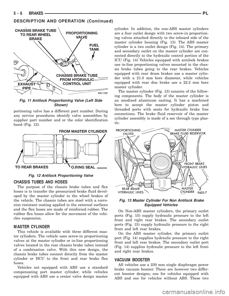
portioning valve has a different part number. During
any service procedures identify valve assemblies by
supplier part number and or the color identification
band (Fig. 12).
CHASSIS TUBES AND HOSES
The purpose of the chassis brake tubes and flex
hoses is to transfer the pressurized brake fluid devel-
oped by the master cylinder to the wheel brakes of
the vehicle. The chassis tubes are steel with a corro-
sion resistant coating applied to the external surfaces
and the flex hoses are made of reinforced rubber. The
rubber flex hoses allow for the movement of the vehi-
cles suspension.
MASTER CYLINDER
This vehicle is available with three different mas-
ter cylinders. The vehicle uses screw-in proportioning
valves at the master cylinder or in-line proportioning
valves located in the rear chassis brake tubes instead
of a combination valve. With this new design, the
chassis brake tubes connect directly from the master
cylinder or HCU to the front and rear brake flex
hoses.
Vehicles not equipped with ABS use a standard
compensating port master cylinder, while vehicles
equipped with ABS use a center valve design mastercylinder. In addition, the non-ABS master cylinders
are a four outlet design with two screw-in proportion-
ing valves attached directly to the inboard side of the
master cylinder housing (Fig. 13). The ABS master
cylinder is a two outlet design (Fig. 14). The primary
and secondary outlet on the master cylinder are con-
nected directly to the hydraulic control portion of the
ICU (Fig. 14) Vehicles equipped with antilock brakes
use in-line proportioning valves mounted in the chas-
sis brake tubes going to the rear brakes. Vehicles
equipped with rear drum brakes use a master cylin-
der with a 21.0 mm bore diameter, while vehicles
equipped with rear disc brake use a 22.2 mm bore
master cylinder.
The master cylinder (Fig. 13) consists of the follow-
ing components. The body of the master cylinder is
an anodized aluminum casting. It has a machined
bore to accept the master cylinder piston and
threaded ports with seats for hydraulic brake line
connections. The brake fluid reservoir of the master
cylinder assembly is made of a see through type plas-
tic.
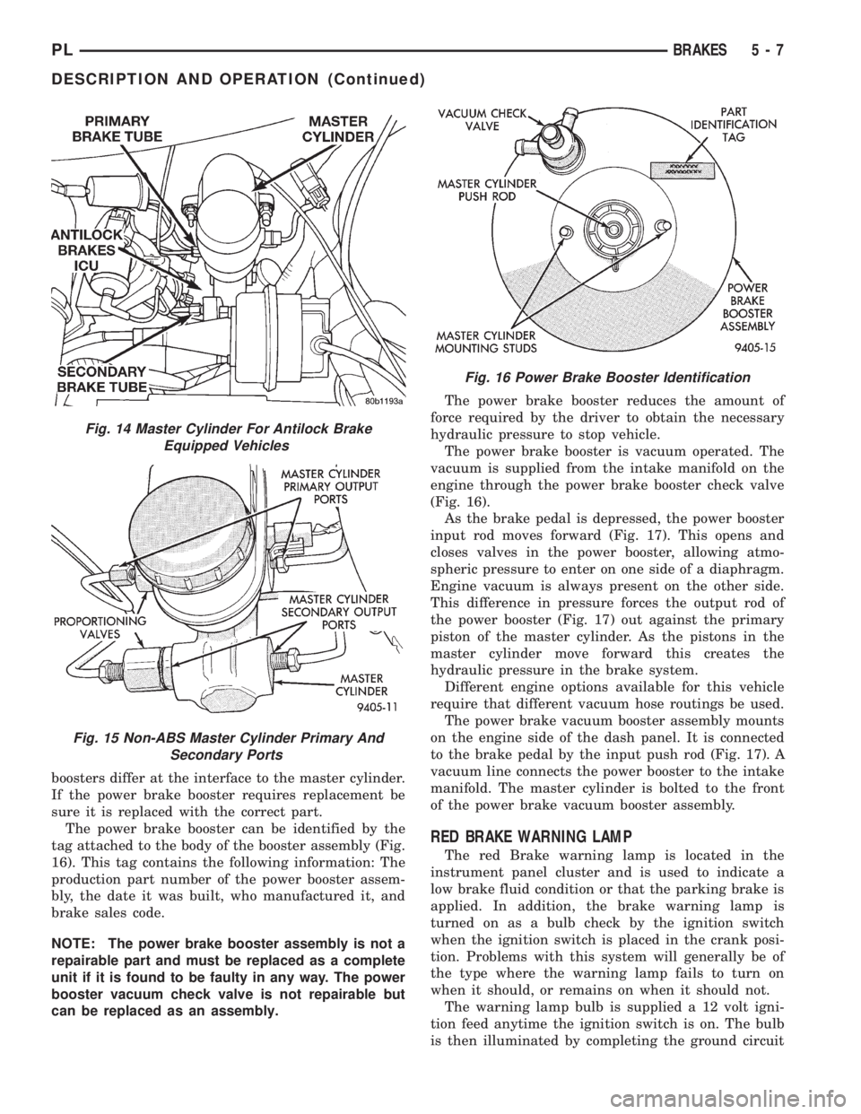
On Non-ABS master cylinders, the primary outlet
ports (Fig. 15) supply hydraulic pressure to the left
front and right rear brakes. The secondary outlet
ports (Fig. 15) supply hydraulic pressure to the right
front and left rear brakes.
On the ABS master cylinder, the primary outlet
port (Fig. 14) supplies hydraulic pressure to the right
front and left rear brakes. The secondary outlet port
(Fig. 14) supplies hydraulic pressure to the left front
and right rear brakes.
VACUUM BOOSTER
All vehicles use a 230 mm single diaphragm power
brake vacuum booster. There are however two differ-
ent booster designs; one for vehicles equipped with
ABS and one for vehicles without ABS. These two
Fig. 11 Antilock Proportioning Valve (Left Side
Shown)
Fig. 12 Antilock Proportioning Valve
Fig. 13 Master Cylinder For Non Antilock Brake
Equipped Vehicles
5 - 6 BRAKESPL
DESCRIPTION AND OPERATION (Continued)
Page 88 of 1200
boosters differ at the interface to the master cylinder.
If the power brake booster requires replacement be
sure it is replaced with the correct part.
The power brake booster can be identified by the
tag attached to the body of the booster assembly (Fig.
16). This tag contains the following information: The
production part number of the power booster assem-
bly, the date it was built, who manufactured it, and
brake sales code.
NOTE: The power brake booster assembly is not a
repairable part and must be replaced as a complete
unit if it is found to be faulty in any way. The power
booster vacuum check valve is not repairable but
can be replaced as an assembly.The power brake booster reduces the amount of
force required by the driver to obtain the necessary
hydraulic pressure to stop vehicle.
The power brake booster is vacuum operated. The
vacuum is supplied from the intake manifold on the
engine through the power brake booster check valve
(Fig. 16).
As the brake pedal is depressed, the power booster
input rod moves forward (Fig. 17). This opens and
closes valves in the power booster, allowing atmo-
spheric pressure to enter on one side of a diaphragm.
Engine vacuum is always present on the other side.
This difference in pressure forces the output rod of
the power booster (Fig. 17) out against the primary
piston of the master cylinder. As the pistons in the
master cylinder move forward this creates the
hydraulic pressure in the brake system.
Different engine options available for this vehicle
require that different vacuum hose routings be used.
The power brake vacuum booster assembly mounts
on the engine side of the dash panel. It is connected
to the brake pedal by the input push rod (Fig. 17). A
vacuum line connects the power booster to the intake
manifold. The master cylinder is bolted to the front
of the power brake vacuum booster assembly.
RED BRAKE WARNING LAMP
The red Brake warning lamp is located in the
instrument panel cluster and is used to indicate a
low brake fluid condition or that the parking brake is
applied. In addition, the brake warning lamp is
turned on as a bulb check by the ignition switch
when the ignition switch is placed in the crank posi-
tion. Problems with this system will generally be of
the type where the warning lamp fails to turn on
when it should, or remains on when it should not.
The warning lamp bulb is supplied a 12 volt igni-
tion feed anytime the ignition switch is on. The bulb
is then illuminated by completing the ground circuit
Fig. 14 Master Cylinder For Antilock Brake
Equipped Vehicles
Fig. 15 Non-ABS Master Cylinder Primary And
Secondary Ports
Fig. 16 Power Brake Booster Identification
PLBRAKES 5 - 7
DESCRIPTION AND OPERATION (Continued)
Page 89 of 1200

either through the park brake switch, the fluid level
sensor in the master cylinder reservoir, or the igni-
tion switch in the crank position.
The Brake Fluid Level sensor is located in the
brake fluid reservoir of the master cylinder assembly
(Fig. 18). The purpose of the sensor is to provide the
driver with an early warning that the brake fluid
level in the master cylinder reservoir has dropped to
below normal. This may indicate an abnormal loss of
brake fluid in the master cylinder fluid reservoir
resulting from a leak in the hydraulic system.
As the fluid drops below the minimum level, the
fluid level sensor closes the brake warning light cir-
cuit. This will turn on the red brake warning light.
At this time, master cylinder fluid reservoir shouldbe checked and filled to the full mark with DOT 3
brake fluid.If brake fluid level has dropped in
master cylinder fluid reservoir, the entire
brake hydraulic system should be checked for
evidence of a leak.
STOP LAMP SWITCH
The stop lamp switch controls operation of the
vehicles stop lamps. Also, if the vehicle is equipped
with speed control, the stop lamp switch will deacti-
vate speed control when the brake pedal is
depressed.
The stop lamp switch controls operation of the
right and left tail, stop and turn signal lamp and
CHMSL lamp, by supplying battery current to these
lamps.
The stop lamp switch controls the lamp operation
by opening and closing the electrical circuit to the
stop lamps.
REAR WHEEL HUB/BEARING
CAUTION: If a vehicle is equipped with antilock
brakes the tone wheels for the rear wheel speed
sensors are pressed onto the hub. The tone wheels
used on this vehicle equipped with the Teves Mark
20 Antilock Brake System are different then those
used on past models of this vehicle equipped with
antilock brakes. Reduced braking performance will
result if this part is used on earlier model vehicles
and an accident could result. Do not use on
pre-1998 model year vehicles.
All vehicles are equipped with permanently lubri-
cated and sealed for life rear wheel bearings. There
is no periodic lubrication or maintenance recom-
mended for these units. However, if servicing of a
rear wheel bearing is required, refer to procedures in
the diagnosis and testing section and the removal
and installation section in this group of the service
manual for the inspection and replacement of the
rear wheel bearing.Fig. 17 Power Brake Booster Assembly
Fig. 18 Master Cylinder Fluid Level Sensor
5 - 8 BRAKESPL
DESCRIPTION AND OPERATION (Continued)
Page 99 of 1200
use the following procedure to diagnose the propor-
tioning valve.
The test procedure is the same for both rear pro-
portioning valves. After road testing the vehicle to
determine which wheel skids first, follow the proce-
dure below for testing the required proportioning
valve.
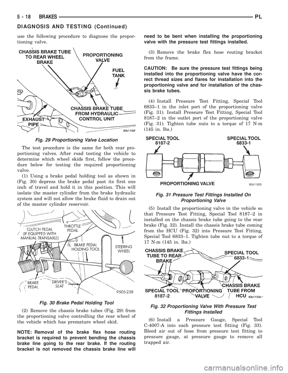
(1) Using a brake pedal holding tool as shown in
(Fig. 30) depress the brake pedal past its first one
inch of travel and hold it in this position. This will
isolate the master cylinder from the brake hydraulic
system and will not allow the brake fluid to drain out
of the master cylinder reservoir.
(2) Remove the chassis brake tubes (Fig. 29) from
the proportioning valve controlling the rear wheel of
the vehicle which has premature wheel skid.
NOTE: Removal of the brake flex hose routing
bracket is required to prevent bending the chassis
brake line going to the rear brake. If the routing
bracket is not removed the chassis brake line willneed to be bent when installing the proportioning
valve with the pressure test fittings installed.
(3) Remove the brake flex hose routing bracket
from the frame.
CAUTION: Be sure the pressure test fittings being
installed into the proportioning valve have the cor-
rect thread sizes and flares for installation into the
proportioning valve and for installation of the chas-
sis brake tubes.
(4) Install Pressure Test Fitting, Special Tool
6833±1 in the inlet port of the proportioning valve
(Fig. 31). Install Pressure Test Fitting, Special Tool
8187±2 in the outlet port of the proportioning valve
(Fig. 31). Tighten tube nuts to a torque of 17 N´m
(145 in. lbs.)
(5) Install the proportioning valve in the vehicle so
that Pressure Test Fitting, Special Tool 8187±2 in
installed on the chassis brake tube going to the rear
brake (Fig. 32). Install the chassis brake tube coming
from the HCU (Fig. 32) into Pressure Test Fitting,
Special Tool 6833±1. Tighten tube nut to a torque of
17 N´m (145 in. lbs.)
(6) Install a Pressure Gauge, Special Tool
C-4007-A into each pressure test fitting (Fig. 33).
Bleed air out of hose from pressure test fitting to
pressure gauge, at pressure gauge to remove all
trapped air.
Fig. 29 Proportioning Valve Location
Fig. 30 Brake Pedal Holding Tool
Fig. 31 Pressure Test Fittings Installed On
Proportioning Valve
Fig. 32 Proportioning Valve With Pressure Test
Fittings Installed
5 - 18 BRAKESPL
DIAGNOSIS AND TESTING (Continued)
Page 100 of 1200
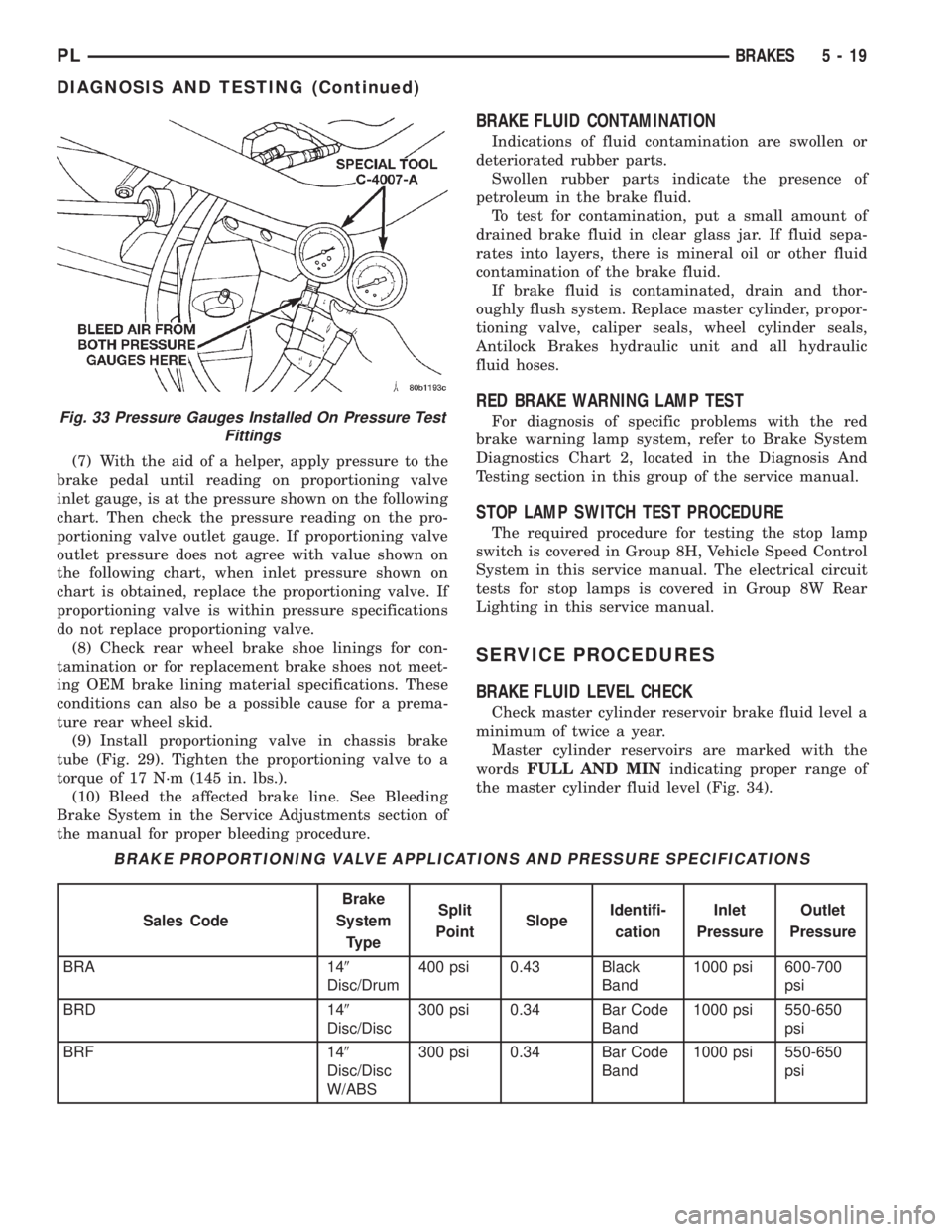
(7) With the aid of a helper, apply pressure to the
brake pedal until reading on proportioning valve
inlet gauge, is at the pressure shown on the following
chart. Then check the pressure reading on the pro-
portioning valve outlet gauge. If proportioning valve
outlet pressure does not agree with value shown on
the following chart, when inlet pressure shown on
chart is obtained, replace the proportioning valve. If
proportioning valve is within pressure specifications
do not replace proportioning valve.
(8) Check rear wheel brake shoe linings for con-
tamination or for replacement brake shoes not meet-
ing OEM brake lining material specifications. These
conditions can also be a possible cause for a prema-
ture rear wheel skid.
(9) Install proportioning valve in chassis brake
tube (Fig. 29). Tighten the proportioning valve to a
torque of 17 N´m (145 in. lbs.).
(10) Bleed the affected brake line. See Bleeding
Brake System in the Service Adjustments section of
the manual for proper bleeding procedure.
BRAKE FLUID CONTAMINATION
Indications of fluid contamination are swollen or
deteriorated rubber parts.
Swollen rubber parts indicate the presence of
petroleum in the brake fluid.
To test for contamination, put a small amount of
drained brake fluid in clear glass jar. If fluid sepa-
rates into layers, there is mineral oil or other fluid
contamination of the brake fluid.
If brake fluid is contaminated, drain and thor-
oughly flush system. Replace master cylinder, propor-
tioning valve, caliper seals, wheel cylinder seals,
Antilock Brakes hydraulic unit and all hydraulic
fluid hoses.
RED BRAKE WARNING LAMP TEST
For diagnosis of specific problems with the red
brake warning lamp system, refer to Brake System
Diagnostics Chart 2, located in the Diagnosis And
Testing section in this group of the service manual.
STOP LAMP SWITCH TEST PROCEDURE
The required procedure for testing the stop lamp
switch is covered in Group 8H, Vehicle Speed Control
System in this service manual. The electrical circuit
tests for stop lamps is covered in Group 8W Rear
Lighting in this service manual.
SERVICE PROCEDURES
BRAKE FLUID LEVEL CHECK
Check master cylinder reservoir brake fluid level a
minimum of twice a year.
Master cylinder reservoirs are marked with the
wordsFULL AND MINindicating proper range of
the master cylinder fluid level (Fig. 34).
Fig. 33 Pressure Gauges Installed On Pressure Test
Fittings
BRAKE PROPORTIONING VALVE APPLICATIONS AND PRESSURE SPECIFICATIONS
Sales CodeBrake
System
TypeSplit
PointSlopeIdentifi-
cationInlet
PressureOutlet
Pressure
BRA 149
Disc/Drum400 psi 0.43 Black
Band1000 psi 600-700
psi
BRD 149
Disc/Disc300 psi 0.34 Bar Code
Band1000 psi 550-650
psi
BRF 149
Disc/Disc
W/ABS300 psi 0.34 Bar Code
Band1000 psi 550-650
psi
PLBRAKES 5 - 19
DIAGNOSIS AND TESTING (Continued)
Page 101 of 1200
CAUTION: Use only MoparTbrake fluid or an
equivalent from a tightly sealed container. Brake
fluid must conform to DOT 3 specifications. Do not
use petroleum-based fluid because seal damage in
the brake system will result.
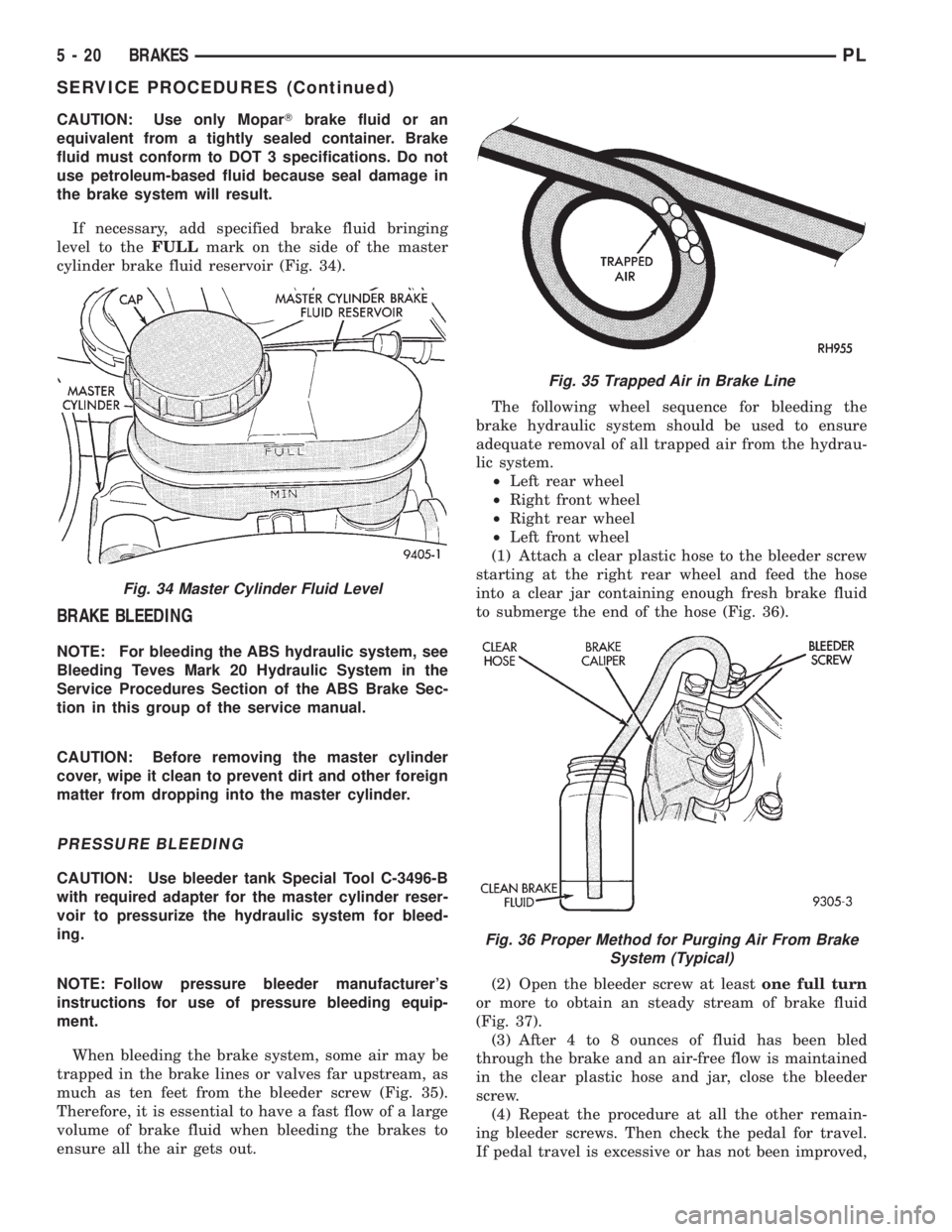
If necessary, add specified brake fluid bringing
level to theFULLmark on the side of the master
cylinder brake fluid reservoir (Fig. 34).
BRAKE BLEEDING
NOTE: For bleeding the ABS hydraulic system, see
Bleeding Teves Mark 20 Hydraulic System in the
Service Procedures Section of the ABS Brake Sec-
tion in this group of the service manual.
CAUTION: Before removing the master cylinder
cover, wipe it clean to prevent dirt and other foreign
matter from dropping into the master cylinder.
PRESSURE BLEEDING
CAUTION: Use bleeder tank Special Tool C-3496-B
with required adapter for the master cylinder reser-
voir to pressurize the hydraulic system for bleed-
ing.
NOTE: Follow pressure bleeder manufacturer's
instructions for use of pressure bleeding equip-
ment.
When bleeding the brake system, some air may be
trapped in the brake lines or valves far upstream, as
much as ten feet from the bleeder screw (Fig. 35).
Therefore, it is essential to have a fast flow of a large
volume of brake fluid when bleeding the brakes to
ensure all the air gets out.The following wheel sequence for bleeding the
brake hydraulic system should be used to ensure
adequate removal of all trapped air from the hydrau-
lic system.
²Left rear wheel
²Right front wheel
²Right rear wheel
²Left front wheel
(1) Attach a clear plastic hose to the bleeder screw
starting at the right rear wheel and feed the hose
into a clear jar containing enough fresh brake fluid
to submerge the end of the hose (Fig. 36).
(2) Open the bleeder screw at leastone full turn
or more to obtain an steady stream of brake fluid
(Fig. 37).
(3) After 4 to 8 ounces of fluid has been bled
through the brake and an air-free flow is maintained
in the clear plastic hose and jar, close the bleeder
screw.
(4) Repeat the procedure at all the other remain-
ing bleeder screws. Then check the pedal for travel.
If pedal travel is excessive or has not been improved,
Fig. 34 Master Cylinder Fluid Level
Fig. 35 Trapped Air in Brake Line
Fig. 36 Proper Method for Purging Air From Brake
System (Typical)
5 - 20 BRAKESPL
SERVICE PROCEDURES (Continued)