1999 DODGE NEON heater
[x] Cancel search: heaterPage 217 of 1200
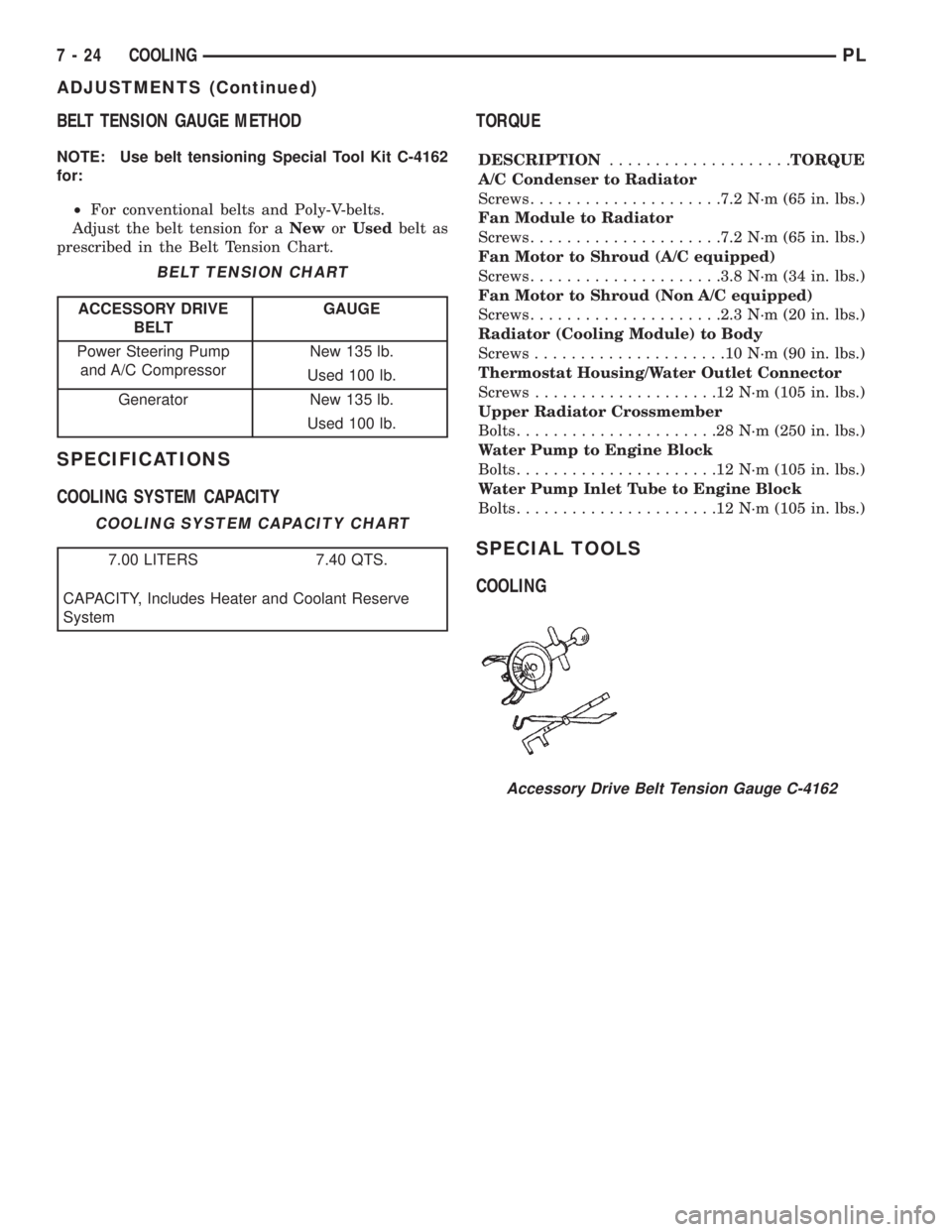
BELT TENSION GAUGE METHOD
NOTE: Use belt tensioning Special Tool Kit C-4162
for:
²For conventional belts and Poly-V-belts.
Adjust the belt tension for aNeworUsedbelt as
prescribed in the Belt Tension Chart.
SPECIFICATIONS
COOLING SYSTEM CAPACITYTORQUE
DESCRIPTION....................TORQUE
A/C Condenser to Radiator
Screws.....................7.2 N´m (65 in. lbs.)
Fan Module to Radiator
Screws.....................7.2 N´m (65 in. lbs.)
Fan Motor to Shroud (A/C equipped)
Screws.....................3.8 N´m (34 in. lbs.)
Fan Motor to Shroud (Non A/C equipped)
Screws.....................2.3 N´m (20 in. lbs.)
Radiator (Cooling Module) to Body
Screws.....................10N´m(90in.lbs.)
Thermostat Housing/Water Outlet Connector
Screws....................12N´m(105 in. lbs.)
Upper Radiator Crossmember
Bolts......................28N´m(250 in. lbs.)
Water Pump to Engine Block
Bolts......................12N´m(105 in. lbs.)
Water Pump Inlet Tube to Engine Block
Bolts......................12N´m(105 in. lbs.)
SPECIAL TOOLS
COOLING
BELT TENSION CHART
ACCESSORY DRIVE
BELTGAUGE
Power Steering Pump
and A/C CompressorNew 135 lb.
Used 100 lb.
Generator New 135 lb.
Used 100 lb.
COOLING SYSTEM CAPACITY CHART
7.00 LITERS 7.40 QTS.
CAPACITY, Includes Heater and Coolant Reserve
System
Accessory Drive Belt Tension Gauge C-4162
7 - 24 COOLINGPL
ADJUSTMENTS (Continued)
Page 242 of 1200
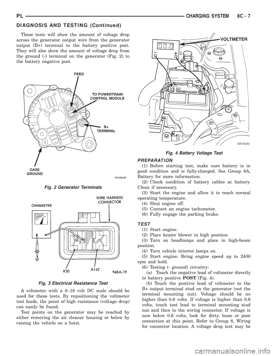
These tests will show the amount of voltage drop
across the generator output wire from the generator
output (B+) terminal to the battery positive post.
They will also show the amount of voltage drop from
the ground (-) terminal on the generator (Fig. 2) to
the battery negative post.
A voltmeter with a 0±18 volt DC scale should be
used for these tests. By repositioning the voltmeter
test leads, the point of high resistance (voltage drop)
can easily be found.
Test points on the generator may be reached by
either removing the air cleaner housing or below by
raising the vehicle on a hoist.
PREPARATION
(1) Before starting test, make sure battery is in
good condition and is fully-charged. See Group 8A,
Battery for more information.
(2) Check condition of battery cables at battery.
Clean if necessary.
(3) Start the engine and allow it to reach normal
operating temperature.
(4) Shut engine off.
(5) Connect an engine tachometer.
(6) Fully engage the parking brake.
TEST
(1) Start engine.
(2) Place heater blower in high position.
(3) Turn on headlamps and place in high-beam
position.
(4) Turn vehicle interior lamps on.
(5) Start engine. Bring engine speed up to 2400
rpm and hold.
(6) Testing (- ground) circuitry:
(a) Touch the negative lead of voltmeter directly
to battery positivePOST(Fig. 4).
(b) Touch the positive lead of voltmeter to the
B+ output terminal stud on the generator (not the
terminal mounting nut). Voltage should be no
higher than 0.6 volts. If voltage is higher than 0.6
volts, touch test lead to terminal mounting stud
nut and then to the wiring connector. If voltage is
now below 0.6 volts, look for dirty, loose or poor
connection at this point. Refer to Group 8, Wiring
for connector location. A voltage drop test may be
Fig. 2 Generator Terminals
Fig. 3 Electrical Resistance Test
Fig. 4 Battery Voltage Test
PLCHARGING SYSTEM 8C - 7
DIAGNOSIS AND TESTING (Continued)
Page 270 of 1200
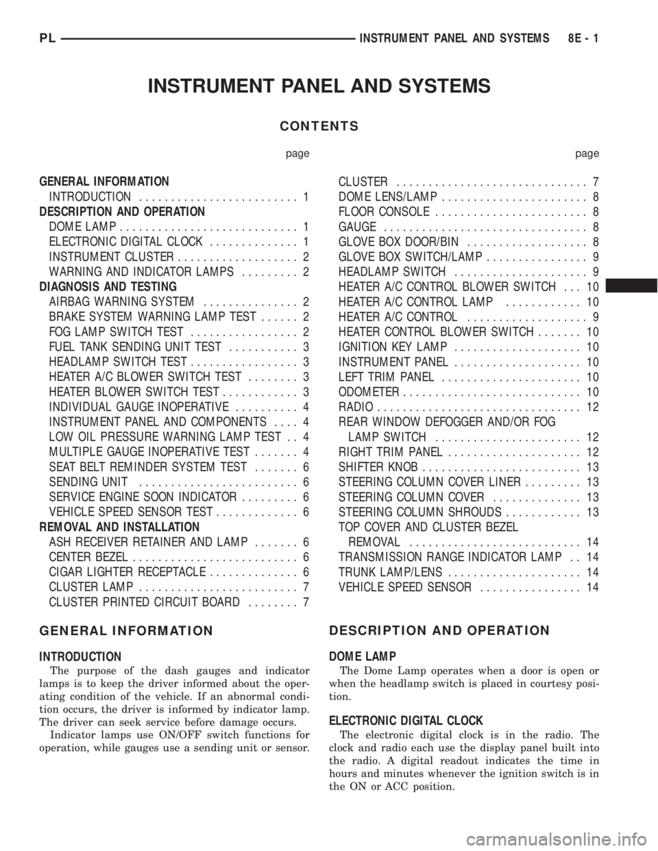
INSTRUMENT PANEL AND SYSTEMS
CONTENTS
page page
GENERAL INFORMATION
INTRODUCTION......................... 1
DESCRIPTION AND OPERATION
DOME LAMP............................ 1
ELECTRONIC DIGITAL CLOCK.............. 1
INSTRUMENT CLUSTER................... 2
WARNING AND INDICATOR LAMPS......... 2
DIAGNOSIS AND TESTING
AIRBAG WARNING SYSTEM............... 2
BRAKE SYSTEM WARNING LAMP TEST...... 2
FOG LAMP SWITCH TEST................. 2
FUEL TANK SENDING UNIT TEST........... 3
HEADLAMP SWITCH TEST................. 3
HEATER A/C BLOWER SWITCH TEST........ 3
HEATER BLOWER SWITCH TEST............ 3
INDIVIDUAL GAUGE INOPERATIVE.......... 4
INSTRUMENT PANEL AND COMPONENTS.... 4
LOW OIL PRESSURE WARNING LAMP TEST . . 4
MULTIPLE GAUGE INOPERATIVE TEST....... 4
SEAT BELT REMINDER SYSTEM TEST....... 6
SENDING UNIT......................... 6
SERVICE ENGINE SOON INDICATOR......... 6
VEHICLE SPEED SENSOR TEST............. 6
REMOVAL AND INSTALLATION
ASH RECEIVER RETAINER AND LAMP....... 6
CENTER BEZEL.......................... 6
CIGAR LIGHTER RECEPTACLE.............. 6
CLUSTER LAMP......................... 7
CLUSTER PRINTED CIRCUIT BOARD........ 7CLUSTER.............................. 7
DOME LENS/LAMP....................... 8
FLOOR CONSOLE........................ 8
GAUGE................................ 8
GLOVE BOX DOOR/BIN................... 8
GLOVE BOX SWITCH/LAMP................ 9
HEADLAMP SWITCH..................... 9
HEATER A/C CONTROL BLOWER SWITCH . . . 10
HEATER A/C CONTROL LAMP............ 10
HEATER A/C CONTROL................... 9
HEATER CONTROL BLOWER SWITCH....... 10
IGNITION KEY LAMP.................... 10
INSTRUMENT PANEL.................... 10
LEFT TRIM PANEL...................... 10
ODOMETER............................ 10
RADIO................................ 12
REAR WINDOW DEFOGGER AND/OR FOG
LAMP SWITCH....................... 12
RIGHT TRIM PANEL..................... 12
SHIFTER KNOB......................... 13
STEERING COLUMN COVER LINER......... 13
STEERING COLUMN COVER.............. 13
STEERING COLUMN SHROUDS............ 13
TOP COVER AND CLUSTER BEZEL
REMOVAL........................... 14
TRANSMISSION RANGE INDICATOR LAMP . . 14
TRUNK LAMP/LENS..................... 14
VEHICLE SPEED SENSOR................ 14
GENERAL INFORMATION
INTRODUCTION
The purpose of the dash gauges and indicator
lamps is to keep the driver informed about the oper-
ating condition of the vehicle. If an abnormal condi-
tion occurs, the driver is informed by indicator lamp.
The driver can seek service before damage occurs.
Indicator lamps use ON/OFF switch functions for
operation, while gauges use a sending unit or sensor.
DESCRIPTION AND OPERATION
DOME LAMP
The Dome Lamp operates when a door is open or
when the headlamp switch is placed in courtesy posi-
tion.
ELECTRONIC DIGITAL CLOCK
The electronic digital clock is in the radio. The
clock and radio each use the display panel built into
the radio. A digital readout indicates the time in
hours and minutes whenever the ignition switch is in
the ON or ACC position.
PLINSTRUMENT PANEL AND SYSTEMS 8E - 1
Page 272 of 1200
FUEL TANK SENDING UNIT TEST
Refer to Group 14, Fuel for test procedures.
HEADLAMP SWITCH TEST
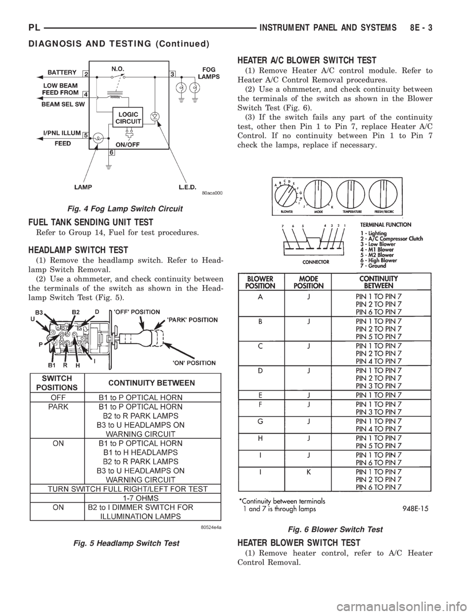
(1) Remove the headlamp switch. Refer to Head-
lamp Switch Removal.
(2) Use a ohmmeter, and check continuity between
the terminals of the switch as shown in the Head-
lamp Switch Test (Fig. 5).
HEATER A/C BLOWER SWITCH TEST
(1) Remove Heater A/C control module. Refer to
Heater A/C Control Removal procedures.
(2) Use a ohmmeter, and check continuity between
the terminals of the switch as shown in the Blower
Switch Test (Fig. 6).
(3) If the switch fails any part of the continuity
test, other then Pin 1 to Pin 7, replace Heater A/C
Control. If no continuity between Pin 1 to Pin 7
check the lamps, replace if necessary.
HEATER BLOWER SWITCH TEST
(1) Remove heater control, refer to A/C Heater
Control Removal.
Fig. 4 Fog Lamp Switch Circuit
Fig. 5 Headlamp Switch Test
Fig. 6 Blower Switch Test
PLINSTRUMENT PANEL AND SYSTEMS 8E - 3
DIAGNOSIS AND TESTING (Continued)
Page 273 of 1200
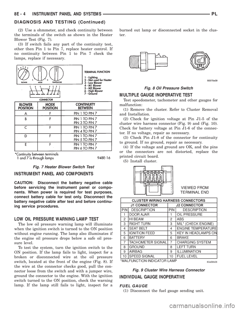
(2) Use a ohmmeter, and check continuity between
the terminals of the switch as shown in the Heater
Blower Test (Fig. 7).
(3) If switch fails any part of the continuity test,
other then Pin 1 to Pin 7, replace heater control. If
no continuity between Pin 1 to Pin 7 check the
lamps, replace if necessary.
INSTRUMENT PANEL AND COMPONENTS
CAUTION: Disconnect the battery negative cable
before servicing the instrument panel or compo-
nents. When power is required for test purposes,
connect battery cable for test only. Disconnect the
battery negative cable after test and before continu-
ing service procedures.
LOW OIL PRESSURE WARNING LAMP TEST
The low oil pressure warning lamp will illuminate
when the ignition switch is turned to the ON position
without engine running. The lamp also illuminates if
the engine oil pressure drops below a safe oil pres-
sure level.
To test the system, turn the ignition switch to the
ON position. If the lamp fails to light, inspect for a
broken or disconnected wire at the oil pressure
switch, located at the front of the engine (Fig. 8). If
the wire at the connector checks good, pull the con-
nector loose from the switch and with a jumper wire,
ground the connector to the engine. With the ignition
switch turned to the ON position, check the warning
lamp. If the lamp still fails to light, inspect for aburned out lamp or disconnected socket in the clus-
ter.
MULTIPLE GAUGE INOPERATIVE TEST
Test speedometer, tachometer and other gauges for
malfunction:
(1) Remove the cluster. Refer to Cluster Removal
and Installation.
(2) Check for ignition voltage at Pin J1-5 of the
cluster wire harness connector (Fig. 9) and (Fig. 10).
Check for battery voltage at Pin J1-6 of the connec-
tor. If no voltage, repair as necessary.
(3) Check Pin J1-8 of the connector for continuity
to ground. If no ground, repair as necessary.
(4) If the voltage and ground are OK, and the pins
or the connectors are not distorted, replace the
printed circuit board.
(5) Install cluster.
INDIVIDUAL GAUGE INOPERATIVE
FUEL GAUGE
(1) Disconnect the fuel gauge sending unit.
Fig. 7 Heater Blower Switch Test
Fig. 8 Oil Pressure Switch
Fig. 9 Cluster Wire Harness Connector
8E - 4 INSTRUMENT PANEL AND SYSTEMSPL
DIAGNOSIS AND TESTING (Continued)
Page 278 of 1200
GLOVE BOX SWITCH/LAMP
REMOVAL
(1) Disconnect battery negative cable and isolate it
or remove fuse 12 prior to removing the switch, or
wires may short to ground.
(2) Open the glove box and push the glove box
sides inward allowing the door bumpers to clear and
the box to tip rearward.
(3) Reach inside the opening and squeeze the
lamp/switch retainers until they are disengage.
(4) Pull the switch/lamp rearward and remove it.
Replace the lamp. To replace the switch disconnect
wire and replace the switch.
INSTALLATION
For installation, reverse the above procedures.
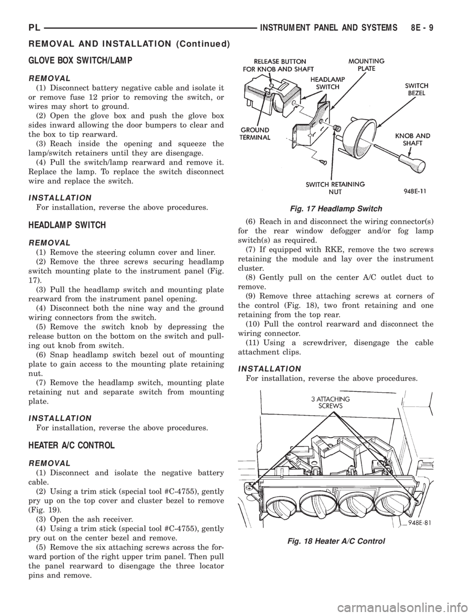
HEADLAMP SWITCH
REMOVAL
(1) Remove the steering column cover and liner.
(2) Remove the three screws securing headlamp
switch mounting plate to the instrument panel (Fig.
17).
(3) Pull the headlamp switch and mounting plate
rearward from the instrument panel opening.
(4) Disconnect both the nine way and the ground
wiring connectors from the switch.
(5) Remove the switch knob by depressing the
release button on the bottom on the switch and pull-
ing out knob from switch.
(6) Snap headlamp switch bezel out of mounting
plate to gain access to the mounting plate retaining
nut.
(7) Remove the headlamp switch, mounting plate
retaining nut and separate switch from mounting
plate.
INSTALLATION
For installation, reverse the above procedures.
HEATER A/C CONTROL
REMOVAL
(1) Disconnect and isolate the negative battery
cable.
(2) Using a trim stick (special tool #C-4755), gently
pry up on the top cover and cluster bezel to remove
(Fig. 19).
(3) Open the ash receiver.
(4) Using a trim stick (special tool #C-4755), gently
pry out on the center bezel and remove.
(5) Remove the six attaching screws across the for-
ward portion of the right upper trim panel. Then pull
the panel rearward to disengage the three locator
pins and remove.(6) Reach in and disconnect the wiring connector(s)
for the rear window defogger and/or fog lamp
switch(s) as required.
(7) If equipped with RKE, remove the two screws
retaining the module and lay over the instrument
cluster.
(8) Gently pull on the center A/C outlet duct to
remove.
(9) Remove three attaching screws at corners of
the control (Fig. 18), two front retaining and one
retaining from the top rear.
(10) Pull the control rearward and disconnect the
wiring connector.
(11) Using a screwdriver, disengage the cable
attachment clips.
INSTALLATION
For installation, reverse the above procedures.
Fig. 17 Headlamp Switch
Fig. 18 Heater A/C Control
PLINSTRUMENT PANEL AND SYSTEMS 8E - 9
REMOVAL AND INSTALLATION (Continued)
Page 279 of 1200
HEATER A/C CONTROL BLOWER SWITCH
The switch is not serviced, replace heater A/C con-
trol. Refer to the Heater A/C Control Removal and
Installation.
HEATER A/C CONTROL LAMP
REMOVAL
(1) Remove the Heater A/C Control. Refer to the
Heater A/C Control Removal.
(2) Remove the two center knobs by pulling the
knob rearward.
(3) Replace the lamp.
INSTALLATION
For installation, reverse the above procedures.
HEATER CONTROL BLOWER SWITCH
The switch is not serviced, replace the heater con-
trol. Refer to the A/C Heater Control Removal and
Installation.
IGNITION KEY LAMP
REMOVAL
(1) Remove the steering column cover. Refer to
Steering Column Cover Removal.
(2) Disconnect the lamp hood from the base panel.
(3) Remove the lamp socket from hood and replace
the lamp.
INSTALLATION
For installation, reverse the above procedures.
INSTRUMENT PANEL
REMOVAL
CAUTION: Disconnect battery negative cable, in
engine compartment, before servicing instrument
panel.
(1) Disconnect and isolate the battery negative
cable.
(2) Remove the floor console. Refer to Floor Con-
sole Removal.
(3) Remove the right and left cowl side trim pan-
els (Fig. 19).
(4) Remove the steering column cover and liner.
(5) Remove the top cover and cluster bezel assem-
bly.
(6) Remove the right and left trim panel.
(7) Remove the defroster upper duct by lifting it
up.
(8) Remove the center outlet duct by pulling rear-
ward.(9) Disconnect the Heater A/C Control, by remov-
ing the control cables clips with a screwdriver and
remove the wire connector.
CAUTION: Lock the steering wheel in the straight
ahead position. This will prevent clockspring dam-
age when the steering wheel rotates freely.
(10) Disconnect the steering column at the bottom
slap together joint.
(11) Disconnect the ATX shifter interlock cable at
the shifter, if equipped.
(12) Disconnect the instrument panel wiring as
required.
(13) Remove the four attaching screws at the cen-
ter floor pan bracket (Fig. 20).
(14) Remove the four attaching screws at steering
column.
(15) Remove the four cowl top nuts.
(16) Remove the attaching screws from the left
and right lower cowl side bracket (Fig. 21).
(17) Remove the two attaching screws from the left
upper cowl side and one from the right upper cowl
side.
(18) Pull the instrument panel rearward away
from the dash/plenum.
(19) Remove the instrument panel from vehicle.
INSTALLATION
For installation, reverse the above procedures.
LEFT TRIM PANEL
REMOVAL
(1) Remove the top cover and cluster bezel (Fig.
19).
(2) Remove the steering column cover.
(3) Remove the two attaching screws along the
bottom and the one at the top of the trim panel and
pull rearward to remove.
INSTALLATION
For installation, reverse the above procedures.
ODOMETER
REMOVAL
(1) Remove the instrument panel top cover and
cluster bezel.
(2) Remove the four screws attaching cluster to
instrument panel (Fig. 22).
(3) Remove the cluster.
(4) Remove the screws attaching PC board cover to
cluster.
(5) Disconnect the odometer connector from the
printed circuit board.
8E - 10 INSTRUMENT PANEL AND SYSTEMSPL
REMOVAL AND INSTALLATION (Continued)
Page 342 of 1200
BULB APPLICATION
INDEX
page page
SPECIFICATIONS
EXTERIOR LAMPS....................... 13GENERAL INFORMATION................. 13
INTERIOR LAMPS....................... 13
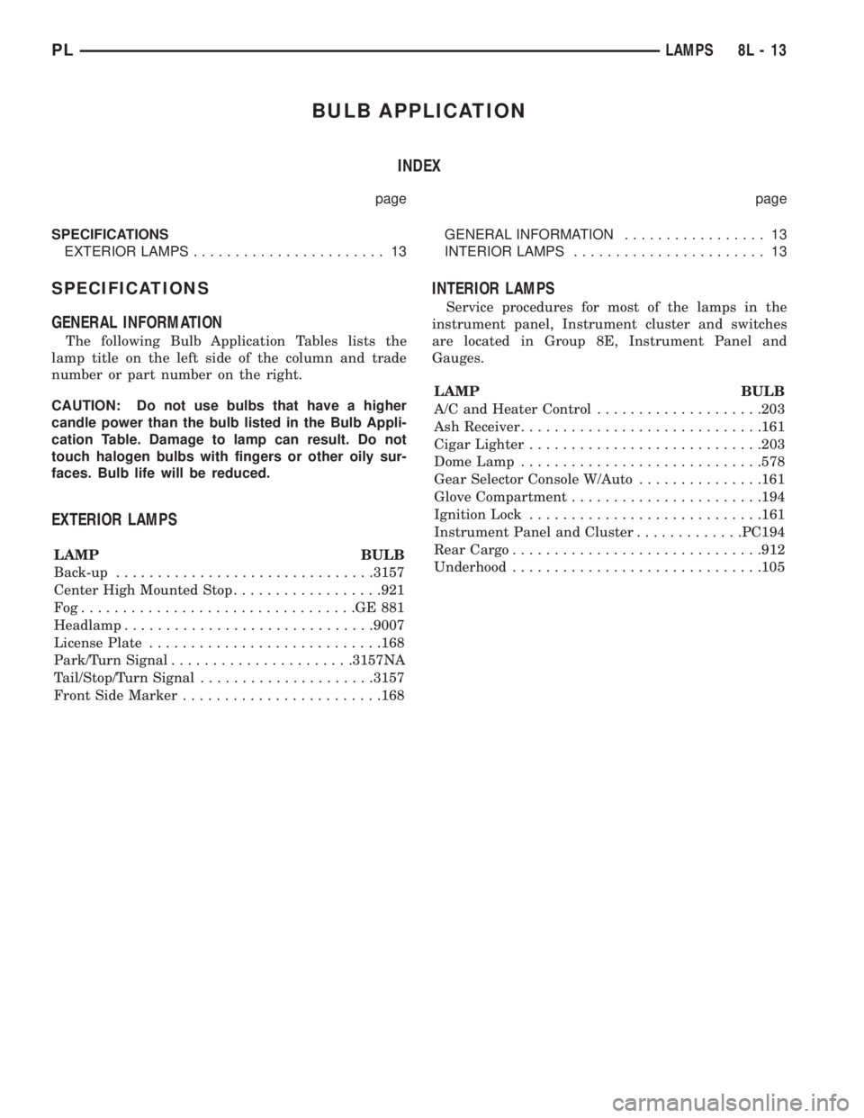
SPECIFICATIONS
GENERAL INFORMATION
The following Bulb Application Tables lists the
lamp title on the left side of the column and trade
number or part number on the right.
CAUTION: Do not use bulbs that have a higher
candle power than the bulb listed in the Bulb Appli-
cation Table. Damage to lamp can result. Do not
touch halogen bulbs with fingers or other oily sur-
faces. Bulb life will be reduced.
EXTERIOR LAMPS
LAMP BULB
Back-up...............................3157
Center High Mounted Stop..................921
Fog.................................GE881
Headlamp..............................9007
License Plate............................168
Park/Turn Signal......................3157NA
Tail/Stop/Turn Signal.....................3157
Front Side Marker........................168
INTERIOR LAMPS
Service procedures for most of the lamps in the
instrument panel, Instrument cluster and switches
are located in Group 8E, Instrument Panel and
Gauges.
LAMP BULB
A/C and Heater Control....................203
Ash Receiver.............................161
Cigar Lighter............................203
Dome Lamp.............................578
Gear Selector Console W/Auto...............161
Glove Compartment.......................194
Ignition Lock............................161
Instrument Panel and Cluster.............PC194
Rear Cargo..............................912
Underhood..............................105
PLLAMPS 8L - 13