1999 DODGE NEON horn
[x] Cancel search: hornPage 360 of 1200
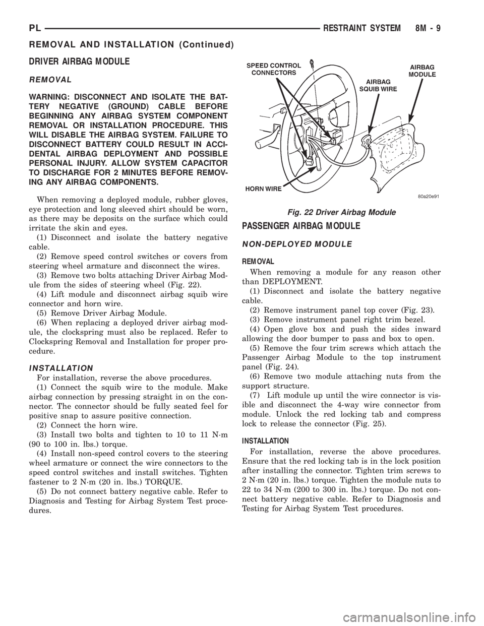
DRIVER AIRBAG MODULE
REMOVAL
WARNING: DISCONNECT AND ISOLATE THE BAT-
TERY NEGATIVE (GROUND) CABLE BEFORE
BEGINNING ANY AIRBAG SYSTEM COMPONENT
REMOVAL OR INSTALLATION PROCEDURE. THIS
WILL DISABLE THE AIRBAG SYSTEM. FAILURE TO
DISCONNECT BATTERY COULD RESULT IN ACCI-
DENTAL AIRBAG DEPLOYMENT AND POSSIBLE
PERSONAL INJURY. ALLOW SYSTEM CAPACITOR
TO DISCHARGE FOR 2 MINUTES BEFORE REMOV-
ING ANY AIRBAG COMPONENTS.
When removing a deployed module, rubber gloves,
eye protection and long sleeved shirt should be worn,
as there may be deposits on the surface which could
irritate the skin and eyes.
(1) Disconnect and isolate the battery negative
cable.
(2) Remove speed control switches or covers from
steering wheel armature and disconnect the wires.
(3) Remove two bolts attaching Driver Airbag Mod-
ule from the sides of steering wheel (Fig. 22).
(4) Lift module and disconnect airbag squib wire
connector and horn wire.
(5) Remove Driver Airbag Module.
(6) When replacing a deployed driver airbag mod-
ule, the clockspring must also be replaced. Refer to
Clockspring Removal and Installation for proper pro-
cedure.
INSTALLATION
For installation, reverse the above procedures.
(1) Connect the squib wire to the module. Make
airbag connection by pressing straight in on the con-
nector. The connector should be fully seated feel for
positive snap to assure positive connection.
(2) Connect the horn wire.
(3) Install two bolts and tighten to 10 to 11 N´m
(90 to 100 in. lbs.) torque.
(4) Install non-speed control covers to the steering
wheel armature or connect the wire connectors to the
speed control switches and install switches. Tighten
fastener to 2 N´m (20 in. lbs.) TORQUE.
(5) Do not connect battery negative cable. Refer to
Diagnosis and Testing for Airbag System Test proce-
dures.
PASSENGER AIRBAG MODULE
NON-DEPLOYED MODULE
REMOVAL
When removing a module for any reason other
than DEPLOYMENT.
(1) Disconnect and isolate the battery negative
cable.
(2) Remove instrument panel top cover (Fig. 23).
(3) Remove instrument panel right trim bezel.
(4) Open glove box and push the sides inward
allowing the door bumper to pass and box to open.
(5) Remove the four trim screws which attach the
Passenger Airbag Module to the top instrument
panel (Fig. 24).
(6) Remove two module attaching nuts from the
support structure.
(7) Lift module up until the wire connector is vis-
ible and disconnect the 4-way wire connector from
module. Unlock the red locking tab and compress
lock to release the connector (Fig. 25).
INSTALLATION
For installation, reverse the above procedures.
Ensure that the red locking tab is in the lock position
after installing the connector. Tighten trim screws to
2 N´m (20 in. lbs.) torque. Tighten the module nuts to
22 to 34 N´m (200 to 300 in. lbs.) torque. Do not con-
nect battery negative cable. Refer to Diagnosis and
Testing for Airbag System Test procedures.
Fig. 22 Driver Airbag Module
PLRESTRAINT SYSTEM 8M - 9
REMOVAL AND INSTALLATION (Continued)
Page 362 of 1200
(5) Lift module and disconnect the airbag and horn
wire connectors.
(6) Remove steering wheel retaining nut.
(7) Remove the steering wheel with a steering
wheel puller. While removing the steering wheel take
care to feed the wires gently through the holes in the
clockspring armature.
INSTALLATION
(1) Confirm that:
²The steering wheel position is a half turn (180
degrees) to the right (clockwise)
²The column is locked with the ignition cylinder
lock.
²Check that the turn signal stalk is in the neu-
tral position
(2) Install the steering wheel ensuring the flats on
hub align with the clockspring. Pull the horn lead,
airbag and speed control leads through the larger
slot. Ensure leads do not get pinched under the steer-
ing wheel.
(3) Install the steering wheel retaining nut, and
tighten it to 61 N´m (45 ft. lbs.) torque.
(4) Install the airbag module. Refer to Driver Air-
bag Module Removal and Installation for proper pro-
cedures.
(5) Do not connect the battery negative cable.
Refer to Diagnosis and Testing for Airbag System
Test procedures.
ADJUSTMENTS
CLOCKSPRING CENTERING PROCEDURE
If the rotating tape within the clockspring is not
positioned properly with the steering wheel and the
front wheels, the clockspring may fail during use.
The following procedure MUST BE USED to center
the clockspring if:²The clockspring is not known to be properly
positioned
²The front wheels were moved
²The steering wheel was moved from the half
turn (180 degrees) to the right (clockwise) position.
WARNING: DISCONNECT AND ISOLATE THE BAT-
TERY NEGATIVE (GROUND) CABLE BEFORE
BEGINNING ANY AIRBAG SYSTEM COMPONENT
REMOVAL OR INSTALLATION PROCEDURE. THIS
WILL DISABLE THE AIRBAG SYSTEM. FAILURE TO
DISCONNECT BATTERY COULD RESULT IN ACCI-
DENTAL AIRBAG DEPLOYMENT AND POSSIBLE
PERSONAL INJURY.
ALLOW SYSTEM CAPACITOR TO DISCHARGE
FOR 2 MINUTES BEFORE REMOVING ANY AIRBAG
COMPONENTS.
(1) Remove clockspring, refer to Clockspring
Removal.
(2) Rotate the clockspring rotor in the CLOCK-
WISE DIRECTION to the end of travel. Do not apply
excessive torque.
(3) From the end of travel, rotate the rotor two full
turns and a half in the counterclockwise direction.
The horn wire and the squib wire should end up at
the bottom. If not, rotate the rotor counter clockwise
until the wires are properly orientated, but not more
than half turn (180 degrees). Engage clockspring
locking mechanism.
(4) For installation, refer to Clockspring Installa-
tion
(5) Do not connect battery negative cable. Refer to
Diagnosis and Testing for Airbag System Test
procedures.
PLRESTRAINT SYSTEM 8M - 11
REMOVAL AND INSTALLATION (Continued)
Page 372 of 1200
REMOTE KEYLESS ENTRY
INDEX
page page
GENERAL INFORMATION
INTRODUCTION......................... 3
DESCRIPTION AND OPERATION
VEHICLE ACCESS CODE (VAC)
PROGRAMMING........................ 3
DIAGNOSIS AND TESTING
REMOTE KEYLESS ENTRY CONDITION....... 4
REMOTE KEYLESS ENTRY SYSTEM......... 5
SERVICE PROCEDURES
HORN CHIRP CANCELLATION.............. 5PANIC FUNCTION CANCELLATION........... 5
PROGRAM REMOTE KEYLESS ENTRY
MODULE.............................. 5
REMOVAL AND INSTALLATION
REMOTE KEYLESS ENTRY MODULE......... 6
SPECIFICATIONS
RKE TRANSMITTER BATTERY.............. 6
RKE TRANSMITTER RANGE................ 6
GENERAL INFORMATION
INTRODUCTION
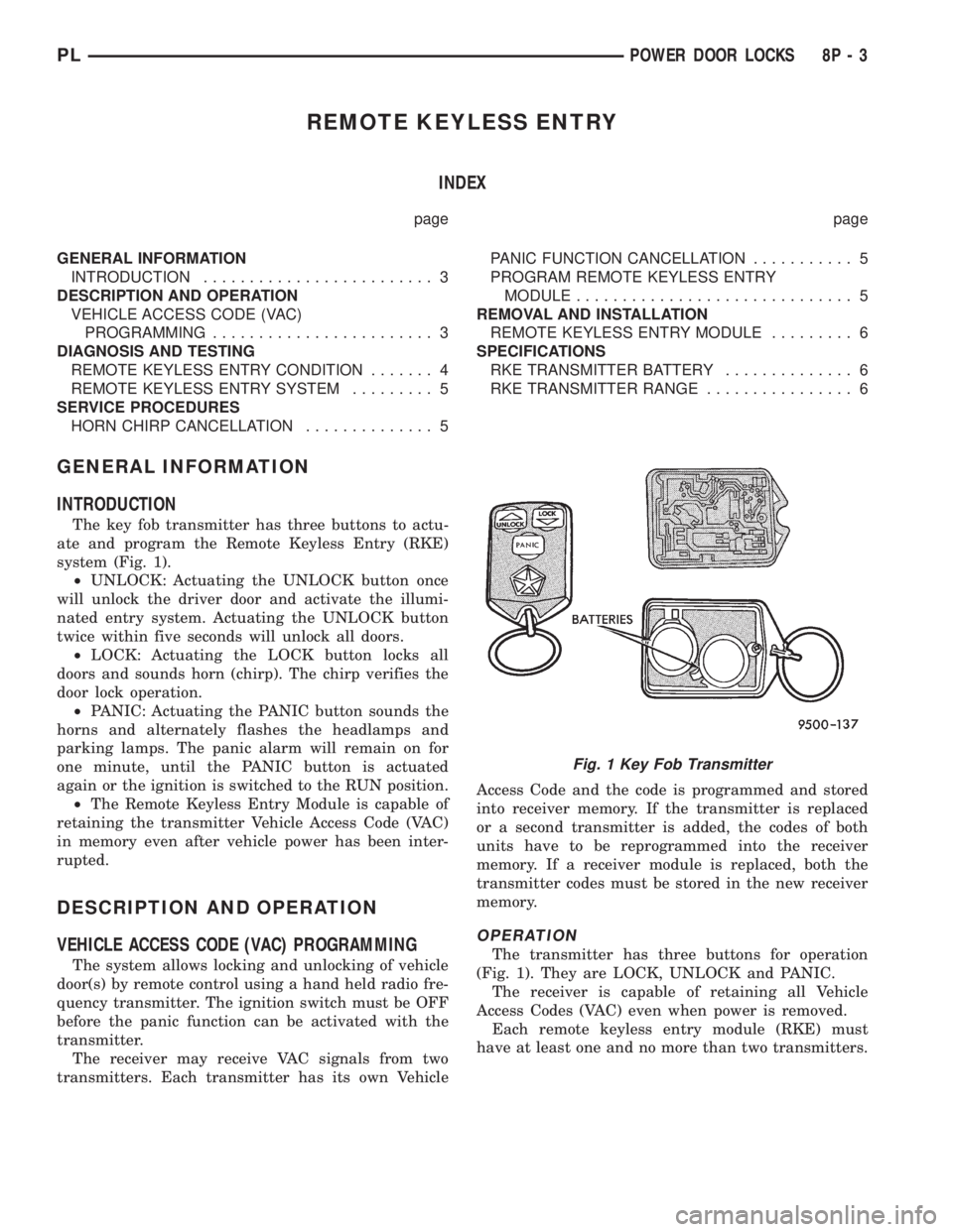
The key fob transmitter has three buttons to actu-
ate and program the Remote Keyless Entry (RKE)
system (Fig. 1).
²UNLOCK: Actuating the UNLOCK button once
will unlock the driver door and activate the illumi-
nated entry system. Actuating the UNLOCK button
twice within five seconds will unlock all doors.
²LOCK: Actuating the LOCK button locks all
doors and sounds horn (chirp). The chirp verifies the
door lock operation.
²PANIC: Actuating the PANIC button sounds the
horns and alternately flashes the headlamps and
parking lamps. The panic alarm will remain on for
one minute, until the PANIC button is actuated
again or the ignition is switched to the RUN position.
²The Remote Keyless Entry Module is capable of
retaining the transmitter Vehicle Access Code (VAC)
in memory even after vehicle power has been inter-
rupted.
DESCRIPTION AND OPERATION
VEHICLE ACCESS CODE (VAC) PROGRAMMING
The system allows locking and unlocking of vehicle
door(s) by remote control using a hand held radio fre-
quency transmitter. The ignition switch must be OFF
before the panic function can be activated with the
transmitter.
The receiver may receive VAC signals from two
transmitters. Each transmitter has its own VehicleAccess Code and the code is programmed and stored
into receiver memory. If the transmitter is replaced
or a second transmitter is added, the codes of both
units have to be reprogrammed into the receiver
memory. If a receiver module is replaced, both the
transmitter codes must be stored in the new receiver
memory.
OPERATION
The transmitter has three buttons for operation
(Fig. 1). They are LOCK, UNLOCK and PANIC.
The receiver is capable of retaining all Vehicle
Access Codes (VAC) even when power is removed.
Each remote keyless entry module (RKE) must
have at least one and no more than two transmitters.
Fig. 1 Key Fob Transmitter
PLPOWER DOOR LOCKS 8P - 3
Page 373 of 1200
DIAGNOSIS AND TESTING
REMOTE KEYLESS ENTRY CONDITION
Use an analog voltmeter for the following test.
REMOTE KEYLESS ENTRY GENERAL CHECKS
BEFORE OTHER CHECKS.
(1) Check if door locks operate properly. If not OK,
repair as necessary.
(2) Disconnect the wire connectors at the RKE
module Using a ohmmeter check for continuity
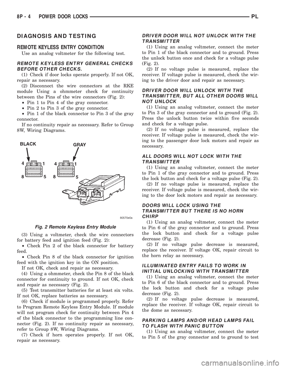
between the Pins of the wire connectors (Fig. 2):
²Pin 1 to Pin 4 of the gray connector.
²Pin 2 to Pin 3 of the gray connector.
²Pin 1 of the black connector to Pin 3 of the gray
connector.
If no continuity repair as necessary. Refer to Group
8W, Wiring Diagrams.
(3) Using a voltmeter, check the wire connectors
for battery feed and ignition feed (Fig. 2):
²Check Pin 2 of the black connector for battery
feed.
²Check Pin 8 of the black connector for ignition
feed with the ignition key in the ON position.
If not OK, check and repair as necessary.
(4) Using a ohmmeter, check the Pin 8 of the black
connector for continuity to ground. If not OK, check
and repair as necessary (Fig. 2).
(5) Test transmitter batteries for at least six volts.
If not OK, replace batteries as necessary.
(6) Check if module is programmed properly. Refer
to Program Remote Keyless Entry Module. If module
will not program check for continuity between Pin 4
of the black connector to the programming line con-
nector (Fig. 2). If no continuity repair as necessary,
refer to Group 8W, Wiring Diagrams.
(7) Check if horn operates properly. If not OK,
repair as necessary.
DRIVER DOOR WILL NOT UNLOCK WITH THE
TRANSMITTER
(1) Using an analog voltmeter, connect the meter
to Pin 1 of the black connector and to ground. Press
the unlock button once and check for a voltage pulse
(Fig. 2).
(2) If no voltage pulse is measured, replace the
receiver. If voltage pulse is measured, check the wir-
ing to the driver door and repair as necessary.
DRIVER DOOR WILL UNLOCK WITH THE
TRANSMITTER, BUT ALL OTHER DOORS WILL
NOT UNLOCK
(1) Using an analog voltmeter, connect the meter
to Pin 3 of the gray connector and to ground (Fig. 2).
Press the unlock button twice within five seconds
and check for a voltage pulse.
(2) If no voltage pulse is measured, replace the
receiver. If voltage pulse is measured, check the wir-
ing to the passenger door lock motors and repair as
necessary.
ALL DOORS WILL NOT LOCK WITH THE
TRANSMITTER
(1) Using an analog voltmeter, connect the meter
to Pin 1 of the gray connector and to ground. Press
the lock button and check for a voltage pulse (Fig. 2).
(2) If no voltage pulse is measured, replace the
receiver. If voltage pulse is measured, check the wir-
ing to the door lock motors and repair as necessary.
DOORS WILL LOCK USING THE
TRANSMITTER BUT THERE IS NO HORN
CHIRP
(1) Using an analog voltmeter, connect the meter
to Pin 6 of the gray connector and to ground. Press
the lock button and check for a voltage pulse
decrease (Fig. 2).
(2) If no voltage pulse decrease is measured,
replace the receiver. If voltage OK, repair circuit to
the horn relay as necessary.
ILLUMINATED ENTRY FAILS TO WORK IN
INITIAL UNLOCKING WITH TRANSMITTER
(1) Using an analog voltmeter, connect the meter
to Pin 6 of the black connector and to ground. Press
the lock button and check for a voltage pulse
decrease (Fig. 2).
(2) If no voltage pulse decrease is measured,
replace the receiver. If voltage OK, repair circuit to
the dome as necessary.
PARKING LAMPS AND/OR HEAD LAMPS FAIL
TO FLASH WITH PANIC BUTTON
(1) Using an analog voltmeter, connect the meter
to Pin 5 of the gray connector and to ground to test
Fig. 2 Remote Keyless Entry Module
8P - 4 POWER DOOR LOCKSPL
Page 374 of 1200
parking lamps out put. Press the panic button and
check for a voltage pulse (Fig. 2).
(2) If no voltage pulse is measured, replace the
receiver. If voltage OK, repair circuit to the parking
lamps as necessary.
(3) Connect the meter to Pin 5 of the black connec-
tor and to ground to test head lamps out put. Press
the panic button and check for a voltage pulse (Fig.
2).
(4) If no voltage pulse is measured, replace the
receiver. If voltage OK, repair circuit to the head
lamps as necessary.
REMOTE KEYLESS ENTRY SYSTEM
When trouble shooting problems with the Remote
Keyless Entry System, always verify that the power
door lock/unlock switches are functional. If the doors
do not lock/unlock refer to Group 8W, Wiring Dia-
gram for Pin and wiring locations.
If the following items do not work:
²Remote keyless entry system
²Radio/clock
²Door lock switches
A blown fuse is the probable cause. Check fuses 2,
3 and 11 in the fuse block. To check for a blown fuse,
pull the fuse out slightly, but maintain contact
between the fuse terminals and the terminals in fuse
block. Using the voltmeter probe, check both termi-
nals for 12 volts. If only one terminal measures bat-
tery voltage, the circuit breaker is defective and must
be replaced. If neither terminal measures battery
voltage, check the high current fuses 3 and 11 in the
Power Distribution Center (PDC). The PDC is located
in the engine compartment. If fuse(s) are NOT OK,
replace fuse(s) or repair as necessary. If fuses are
OK, check for an open or shorted circuit to the Power
Distribution Center, repair as needed.
SERVICE PROCEDURES
HORN CHIRP CANCELLATION
During the programming operation the horn chirp
can be disabled or enable using the following proce-
dure. One or both transmitters can be program to be
disabled or enable.
(1) Retrieve the programming line from the upper
edge of the passenger side cowl trim panel upper
edge. The RKE Programming Line is a green wire
with a red bullet connector.
(2) Using a jumper wire, ground the RKE pro-
gramming line.
(3) Turn ignition switch to the ON position.
(4) Press any button on the transmitter. The locks
will cycle to confirm programming,
(5) To disable or enable horn chirp press the lock
button on the transmitter four times and the hornwill sound to confirm programming. Press the lock
button on the second transmitter four times and the
horn will sound to confirm programming.
(6) Disconnect the programming line from ground.
This returns the system to its normal operation
mode.
(7) Replace any removed components. Return pro-
gramming line chirpto its original position. Check for
system operation.
PANIC FUNCTION CANCELLATION
During the programming operation the panic func-
tion can be disabled or enable using the following
procedure. One or both transmitters can be program
to be disabled or enable.
(1) Retrieve the programming line from the upper
edge of the passenger side cowl trim panel. The RKE
Program Line is a green wire with a red bullet con-
nector.
(2) Using a jumper wire, ground the RKE Pro-
gramming Line.
(3) Turn ignition switch to the ON position.
(4) Press any button on the transmitter. The locks
will cycle to confirm programming,
(5) To disable or enable panic function press the
panic button on the transmitter four times and the
horn will sound to confirm programming. Press the
panic button on the second transmitter four times
and the horn will sound to confirm programming.
(6) Disconnect the programming line from ground.
This returns the system to its normal operation
mode.
(7) Replace any removed components. Return the
programming line to its original position. Check for
system operation.
PROGRAM REMOTE KEYLESS ENTRY MODULE
(1) Retrieve the programming line from the upper
edge of the passenger side cowl trim panel. The RKE
Programming Line is a green wire with a red bullet
connector.
(2) Using a jumper wire, ground the RKE pro-
gramming line.
(3) Turn ignition switch to the ON position.
(4) Press any button on the transmitter to set
code. The locks will cycle to confirm programming. If
there is a second transmitter it must be set at this
time. Press any button on the second transmitter and
wait for the locks to cycle to confirm programming.
(5) Disconnect the programming line from ground.
This returns the system to its normal operation
mode.
(6) Replace all removed components. Return pro-
gramming line to its original position. Check for sys-
tem operation.
PLPOWER DOOR LOCKS 8P - 5
DIAGNOSIS AND TESTING (Continued)
Page 392 of 1200
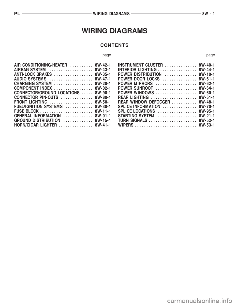
WIRING DIAGRAMS
CONTENTS
page page
AIR CONDITIONING-HEATER.......... 8W-42-1
AIRBAG SYSTEM................... 8W-43-1
ANTI-LOCK BRAKES................. 8W-35-1
AUDIO SYSTEMS................... 8W-47-1
CHARGING SYSTEM................. 8W-20-1
COMPONENT INDEX................. 8W-02-1
CONNECTOR/GROUND LOCATIONS..... 8W-90-1
CONNECTOR PIN-OUTS.............. 8W-80-1
FRONT LIGHTING................... 8W-50-1
FUEL/IGNITION SYSTEMS............ 8W-30-1
FUSE BLOCK....................... 8W-11-1
GENERAL INFORMATION............. 8W-01-1
GROUND DISTRIBUTION............. 8W-15-1
HORN/CIGAR LIGHTER............... 8W-41-1INSTRUMENT CLUSTER.............. 8W-40-1
INTERIOR LIGHTING................. 8W-44-1
POWER DISTRIBUTION.............. 8W-10-1
POWER DOOR LOCKS............... 8W-61-1
POWER MIRRORS.................. 8W-62-1
POWER SUNROOF.................. 8W-64-1
POWER WINDOWS.................. 8W-60-1
REAR LIGHTING.................... 8W-51-1
REAR WINDOW DEFOGGER........... 8W-48-1
SPLICE INFORMATION............... 8W-70-1
SPLICE LOCATIONS................. 8W-95-1
STARTING SYSTEM................. 8W-21-1
TURN SIGNALS..................... 8W-52-1
WIPERS........................... 8W-53-1
PLWIRING DIAGRAMS 8W - 1
Page 410 of 1200

8W-02 COMPONENT INDEX
Component Page
A/C Compressor Clutch..................8W-42
A/C Compressor Clutch Relay.............8W-42
A/C Cycling Switch.....................8W-42
A/C Heater Blower Motor................8W-42
A/C Heater Control.....................8W-42
A/C Pressure Switches...................8W-42
ABS Warning Lamp Relay................8W-35
Airbag Control Module...................8W-43
Airbags..............................8W-43
Antenna..............................8W-47
Ash Receiver Lamp.....................8W-44
Automatic Shut Down Relay..............8W-30
Back-Up Lamp Switch...................8W-51
Back-Up Lamps........................8W-51
Battery..............................8W-20
Battery Temperature Sensor..............8W-30
Blower Motor Resistor Block..............8W-42
Brake Warning Lamp Switch...........8W-40, 50
Camshaft Position Sensor................8W-30
Center High Mounted Stop Lamp..........8W-51
Cigar Lighter Relay.....................8W-41
Cigar Lighter/Power Outlet...............8W-41
Circuit Breakers.......................8W-11
Clockspring.....................8W-30, 41, 61
Clutch Pedal Position Switch...........8W-10, 21
Combination Flasher....................8W-52
Controller Anti-Lock Brake...............8W-35
Crankshaft Position Sensor...............8W-30
Data Link Connector....................8W-30
Daytime Running Lamp Module...........8W-50
Diode No. 1........................8W-15, 42
Diode No. 2......................8W-10, 11, 44
Diode No. 3......................8W-11,44,70
Dome Lamp...........................8W-44
Door Ajar Switches.....................8W-44
Door Jamb Switches....................8W-44
Door Lock Motors......................8W-61
Door Lock Motors......................8W-61
Door Lock Switches.....................8W-61
Duty Cycle Evap/Purge Solenoid...........8W-30
EGR Transducer Solenoid................8W-30
Engine Coolant Temperature Sensor........8W-30
Engine Oil Pressure Switch...............8W-40
Engine Starter Motor....................8W-21
Engine Starter Motor Relay...............8W-21
Fog Lamp Relays....................8W-50, 51
Fog Lamp Switches..................8W-50, 51
Fog Lamps.........................8W-50, 51
Fuel Injectors..........................8W-30
Fuel Pump Module.....................8W-30
Fuel Pump Relay.......................8W-30
Fuse Block............................8W-11Component Page
Fuses (FB)............................8W-11
Fuses (PDC)...........................8W-10
Fusible Link........................8W-20, 21
Generator.............................8W-20
Glove Box Lamp And Switch..............8W-44
Grounds..............................8W-15
Halo Lamp............................8W-44
Headlamp Dimmer And Optical Horn Switch .8W-50
Headlamp Leveling Motors...............8W-50
Headlamp Leveling Switch...............8W-50
Headlamp Switch.......................8W-50
Headlamps............................8W-50
High Speed Warning Module..............8W-40
Horn Relay...........................8W-41
Horn Switches.........................8W-41
Horns................................8W-41
IAT/Map Sensor........................8W-30
Idle Air Control Motor...................8W-30
Ignition Coil Pack......................8W-30
Ignition Switch........................8W-10
Illumination Lamps.....................8W-40
Immobilizer...........................8W-61
Immobilizer Engine Sensor............8W-30, 61
Indicator Lamps........................8W-40
Instrument Cluster.....................8W-40
Intermittent Wipe/Wash Switch............8W-53
Key-In Switch.........................8W-40
Knock Sensor..........................8W-30
License Lamps.........................8W-51
Map/Reading Lamps....................8W-44
Noise Supressor.....................8W-10, 30
Oxygen Sensors........................8W-30
Park Brake Switch...................8W-40, 50
Park/Neutral Position Switch...........8W-30, 51
Park/Turn Signal Lamps..............8W-50, 52
Power Distribution Center................8W-10
Power Folding Mirror Relay...............8W-62
Power Mirror Fuse Holder................8W-62
Power Mirrors.........................8W-62
Power Steering Pressure Switch...........8W-30
Power Sunroof Motor....................8W-64
Power Window Motors...................8W-60
Power Window Switches.................8W-60
Powertrain Control Module...............8W-30
PRNDL Lamp.........................8W-44
Radiator Fan Motor.....................8W-42
Radio................................8W-47
Rear Window Defogger..................8W-48
Rear Window Defogger Switch.............8W-48
Remote Keyless Entry Module.............8W-61
Remote Keyless Entry Program
Module Connector....................8W-61
PL8W - 02 COMPONENT INDEX 8W - 02 - 1
Page 412 of 1200
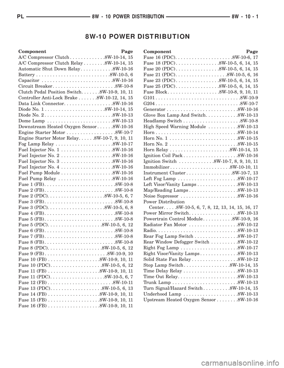
8W-10 POWER DISTRIBUTION
Component Page
A/C Compressor Clutch.............8W-10-14, 15
A/C Compressor Clutch Relay........8W-10-14, 15
Automatic Shut Down Relay............8W-10-16
Battery...........................8W-10-5, 6
Capacitor..........................8W-10-16
Circuit Breaker.......................8W-10-8
Clutch Pedal Position Switch.......8W-10-9, 10, 11
Controller Anti-Lock Brake.......8W-10-12, 14, 15
Data Link Connector..................8W-10-16
Diode No. 1......................8W-10-14, 15
Diode No. 2.........................8W-10-13
Dome Lamp........................8W-10-13
Downstream Heated Oxygen Sensor......8W-10-16
Engine Starter Motor..................8W-10-7
Engine Starter Motor Relay......8W-10-7, 9, 10, 11
Fog Lamp Relay.....................8W-10-17
Fuel Injector No. 1...................8W-10-16
Fuel Injector No. 2...................8W-10-16
Fuel Injector No. 3...................8W-10-16
Fuel Injector No. 4...................8W-10-16
Fuel Pump Module...................8W-10-16
Fuel Pump Relay....................8W-10-16
Fuse 1 (FB)..........................8W-10-8
Fuse 2 (FB)..........................8W-10-8
Fuse 2 (PDC).....................8W-10-5, 6, 7
Fuse 3 (FB)..........................8W-10-8
Fuse 3 (PDC).....................8W-10-5, 6, 8
Fuse 4 (FB)..........................8W-10-8
Fuse 5 (FB)..........................8W-10-8
Fuse 5 (PDC)....................8W-10-5, 6, 12
Fuse 6 (FB)..........................8W-10-8
Fuse 7 (FB)..........................8W-10-8
Fuse 8 (FB)..........................8W-10-8
Fuse 8 (PDC)....................8W-10-5, 6, 12
Fuse 9 (FB).......................8W-10-9, 10
Fuse 10 (FB)...................8W-10-9, 10, 11
Fuse 10 (PDC)...................8W-10-5, 6, 12
Fuse 11 (FB)...................8W-10-9, 10, 11
Fuse 11 (PDC)....................8W-10-5, 6, 7
Fuse 12 (FB)........................8W-10-11
Fuse 13 (PDC)...................8W-10-5, 6, 13
Fuse 14 (FB)...................8W-10-9, 10, 11
Fuse 15 (FB)...................8W-10-9, 10, 11
Fuse 16 (FB)...................8W-10-9, 10, 11Component Page
Fuse 16 (PDC).....................8W-10-6, 17
Fuse 18 (PDC)................8W-10-5, 6, 14, 15
Fuse 20 (PDC)................8W-10-5, 6, 14, 15
Fuse 21 (PDC)...................8W-10-5, 6, 16
Fuse 23 (PDC)................8W-10-5, 6, 14, 15
Fuse 25 (PDC)................8W-10-5, 6, 14, 15
Fuse Block...................8W-10-8, 9, 10, 11
G101...............................8W-10-9
G204...............................8W-10-7
Generator..........................8W-10-16
Glove Box Lamp And Switch............8W-10-13
Headlamp Switch.....................8W-10-8
High Speed Warning Module...........8W-10-13
Horn..............................8W-10-14
Horn No. 1.........................8W-10-15
Horn No. 2.........................8W-10-15
Horn Relay......................8W-10-14, 15
Ignition Coil Pack....................8W-10-16
Ignition Switch.............8W-10-7, 8, 9, 10, 11
Immobilizer......................8W-10-10, 11
Instrument Cluster.................8W-10-7, 13
Left Fog Lamp......................8W-10-17
Left Visor/Vanity Lamps...............8W-10-13
Map/Reading Lamps..................8W-10-13
Noise Supressor.....................8W-10-16
Power Distribution
Center.....8W-10-5, 6, 7, 8, 12, 13, 14, 15, 16, 17
Power Mirror Switch..................8W-10-13
Powertrain Control Module...........8W-10-9, 16
Radiator Fan Motor..................8W-10-12
Radio..............................8W-10-13
Rear Fog Lamp Switch................8W-10-17
Rear Window Defogger Switch..........8W-10-12
Right Fog Lamp.....................8W-10-17
Right Visor/Vanity Lamps..............8W-10-13
Solid State Fan Relay.................8W-10-12
Stop Lamp Switch.................8W-10-14, 15
Time Delay Relay....................8W-10-13
Time Out Relay......................8W-10-13
Trunk Lamp........................8W-10-13
Turn Signal/Hazard Switch..........8W-10-14, 15
Underhood Lamp....................8W-10-13
Upstream Heated Oxygen Sensor........8W-10-16
PL8W - 10 POWER DISTRIBUTION 8W - 10 - 1