1999 DODGE NEON horn
[x] Cancel search: hornPage 677 of 1200
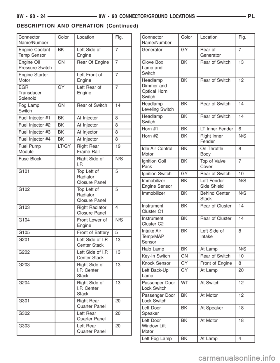
Connector
Name/NumberColor Location Fig.
Engine Coolant
Temp SensorBK Left Side of
Engine7
Engine Oil
Pressure SwitchGN Rear Of Engine 7
Engine Starter
MotorLeft Front of
Engine7
EGR
Transducer
SolenoidGY Left Rear of
Engine7
Fog Lamp
SwitchGN Rear of Switch 14
Fuel Injector #1 BK At Injector 8
Fuel Injector #2 BK At Injector 8
Fuel Injector #3 BK At injector 8
Fuel Injector #4 BK At Injector 8
Fuel Pump
ModuleLT/GY Right Rear
Frame Rail19
Fuse Block Right Side of
I.P.N/S
G101 Top Left of
Radiator
Closure Panel5
G102 Top Left of
Radiator
Closure Panel5
G103 Right Radiator
Closure Panel4
G104 Front Lower of
EngineN/S
G105 Front of Battery 5
G201 Left Side of I.P.
Center Stack13
G202 Left Side of I.P.
Center Stack13
G203 Right Side of
I.P. Center
Stack13
G204 Right Side of
I.P. Center
Stack13
G301 Right Rear
Quarter Panel20
G302 Left Rear
Quarter Panel20
G303 Left Rear
Quarter Panel20Connector
Name/NumberColor Location Fig.
Generator GY Rear of
Generator7
Glove Box
Lamp and
SwitchBK Rear of Switch 13
Headlamp
Dimmer and
Optical Horn
SwitchBK Rear of Switch 12
Headlamp
Leveling SwitchBK Rear of Switch 14
Headlamp
SwitchBK Rear of Switch 14
Horn #1 BK LT Inner Fender 6
Horn #2 BK Right Inner
FenderN/S
Idle Air Control
MotorBK On Throttle
Body8
Ignition Coil
PackBK Top of Valve
Cover7
Ignition Switch GY Rear of Switch 10
Immobilizer
Engine SensorBK Left Fender
Side ShieldN/S
Immobilizer BK Behind Center
StackN/S
Instrument
Cluster C1BK Rear of Cluster 14
Instrument
Cluster C2BK Rear of Cluster 14
Intake Air
Temp/MAP
SensorBK Left Side of
Intake8
Halo Lamp BK At Lamp N/S
Key-In Switch GN Rear of Switch 10
Knock Sensor GY Front of Engine 8
Left Back-Up
LampGY At Lamp 20
Passenger Door
Lock SwitchWT At Switch 12
Passenger Door
Lock SwitchBK At Motor 12
Left Door
SpeakerBK At Speaker 18
Left Door
Window Lift
MotorBK At Motor 18
Left Fog Lamp BK At Lamp 4
8W - 90 - 24 8W - 90 CONNECTOR/GROUND LOCATIONSPL
DESCRIPTION AND OPERATION (Continued)
Page 940 of 1200
WARNING: WHEN HANDLING AN UNDEPLOYED
AIR BAG MODULE DURING SERVICING OF THE
STEERING COLUMN THE FOLLOWING PRECAU-
TIONS SHOULD BE OBSERVED. AT NO TIME
SHOULD ANY SOURCE OF ELECTRICITY BE PER-
MITTED NEAR THE INFLATOR ON THE BACK OF
THE AIR BAG MODULE. WHEN CARRYING A LIVE
MODULE, THE TRIM COVER SHOULD BE POINTED
AWAY FROM THE BODY TO MINIMIZE INJURY IF
MODULE ACCIDENTLY DEPLOYS. IF AIR BAG MOD-
ULE IS PLACED ON A BENCH OR OTHER SUR-
FACE, PLASTIC COVER SHOULD BE FACE UP TO
MINIMIZE MOVEMENT IN CASE OF ACCIDENTAL
DEPLOYMENT.
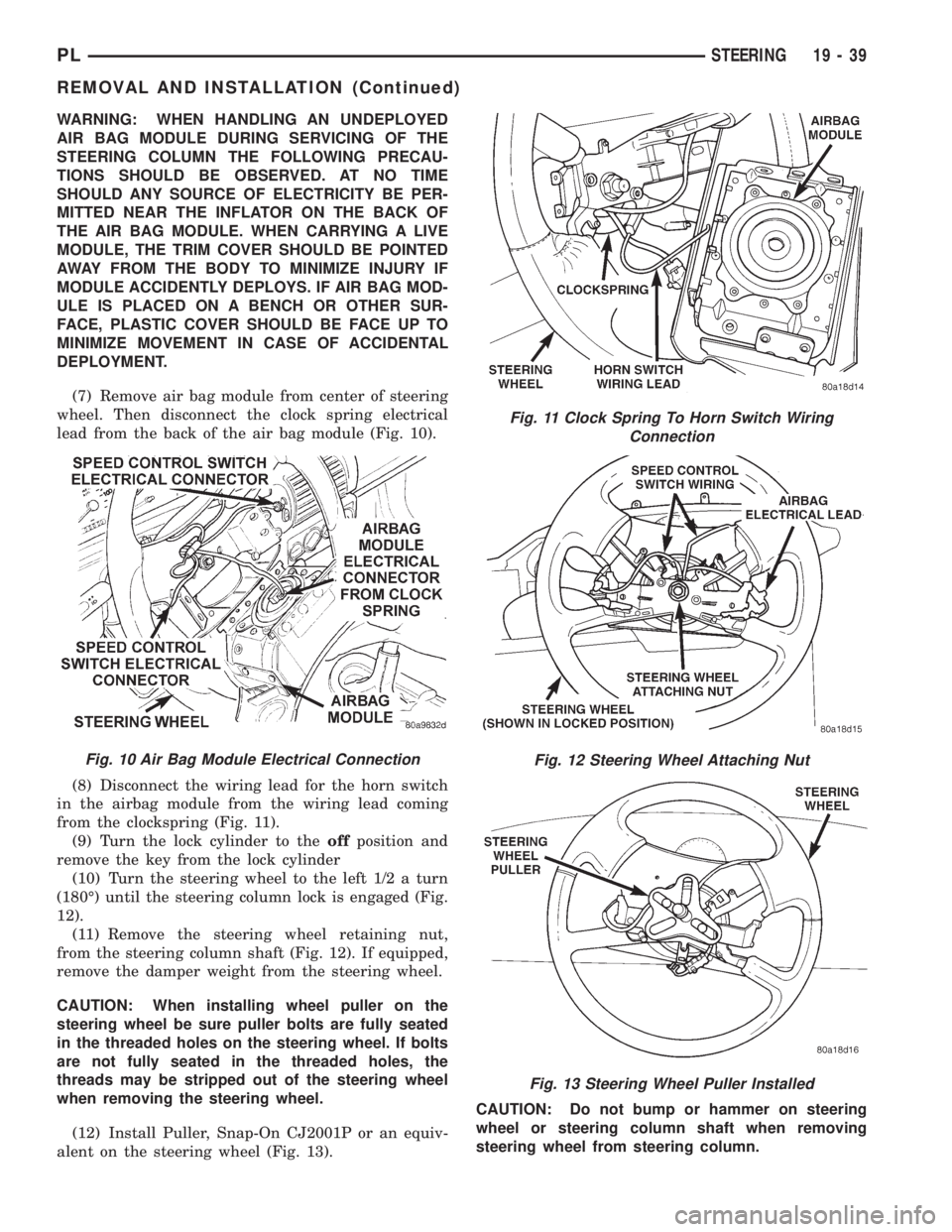
(7) Remove air bag module from center of steering
wheel. Then disconnect the clock spring electrical
lead from the back of the air bag module (Fig. 10).
(8) Disconnect the wiring lead for the horn switch
in the airbag module from the wiring lead coming
from the clockspring (Fig. 11).
(9) Turn the lock cylinder to theoffposition and
remove the key from the lock cylinder
(10) Turn the steering wheel to the left 1/2 a turn
(180É) until the steering column lock is engaged (Fig.
12).
(11) Remove the steering wheel retaining nut,
from the steering column shaft (Fig. 12). If equipped,
remove the damper weight from the steering wheel.
CAUTION: When installing wheel puller on the
steering wheel be sure puller bolts are fully seated
in the threaded holes on the steering wheel. If bolts
are not fully seated in the threaded holes, the
threads may be stripped out of the steering wheel
when removing the steering wheel.
(12) Install Puller, Snap-On CJ2001P or an equiv-
alent on the steering wheel (Fig. 13).CAUTION: Do not bump or hammer on steering
wheel or steering column shaft when removing
steering wheel from steering column.
Fig. 11 Clock Spring To Horn Switch Wiring
Connection
Fig. 12 Steering Wheel Attaching Nut
Fig. 13 Steering Wheel Puller Installed
Fig. 10 Air Bag Module Electrical Connection
PLSTEERING 19 - 39
REMOVAL AND INSTALLATION (Continued)
Page 942 of 1200
(23) Remove steering column from vehicle through
the drivers door of the passenger compartment. Use
care to avoid damaging the paint or interior trim.
INSTALL
(1) Install steering column into steering column
access opening in lower instrument panel.
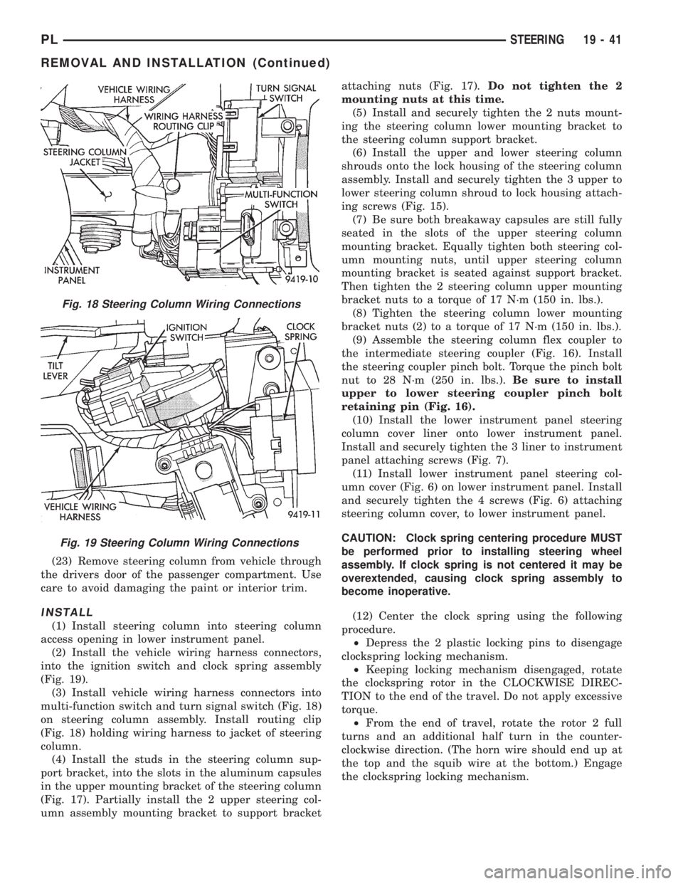
(2) Install the vehicle wiring harness connectors,
into the ignition switch and clock spring assembly
(Fig. 19).
(3) Install vehicle wiring harness connectors into
multi-function switch and turn signal switch (Fig. 18)
on steering column assembly. Install routing clip
(Fig. 18) holding wiring harness to jacket of steering
column.
(4) Install the studs in the steering column sup-
port bracket, into the slots in the aluminum capsules
in the upper mounting bracket of the steering column
(Fig. 17). Partially install the 2 upper steering col-
umn assembly mounting bracket to support bracketattaching nuts (Fig. 17).Do not tighten the 2
mounting nuts at this time.
(5) Install and securely tighten the 2 nuts mount-
ing the steering column lower mounting bracket to
the steering column support bracket.
(6) Install the upper and lower steering column
shrouds onto the lock housing of the steering column
assembly. Install and securely tighten the 3 upper to
lower steering column shroud to lock housing attach-
ing screws (Fig. 15).
(7) Be sure both breakaway capsules are still fully
seated in the slots of the upper steering column
mounting bracket. Equally tighten both steering col-
umn mounting nuts, until upper steering column
mounting bracket is seated against support bracket.
Then tighten the 2 steering column upper mounting
bracket nuts to a torque of 17 N´m (150 in. lbs.).
(8) Tighten the steering column lower mounting
bracket nuts (2) to a torque of 17 N´m (150 in. lbs.).
(9) Assemble the steering column flex coupler to
the intermediate steering coupler (Fig. 16). Install
the steering coupler pinch bolt. Torque the pinch bolt
nut to 28 N´m (250 in. lbs.).Be sure to install
upper to lower steering coupler pinch bolt
retaining pin (Fig. 16).
(10) Install the lower instrument panel steering
column cover liner onto lower instrument panel.
Install and securely tighten the 3 liner to instrument
panel attaching screws (Fig. 7).
(11) Install lower instrument panel steering col-
umn cover (Fig. 6) on lower instrument panel. Install
and securely tighten the 4 screws (Fig. 6) attaching
steering column cover, to lower instrument panel.
CAUTION: Clock spring centering procedure MUST
be performed prior to installing steering wheel
assembly. If clock spring is not centered it may be
overextended, causing clock spring assembly to
become inoperative.
(12) Center the clock spring using the following
procedure.
²Depress the 2 plastic locking pins to disengage
clockspring locking mechanism.
²Keeping locking mechanism disengaged, rotate
the clockspring rotor in the CLOCKWISE DIREC-
TION to the end of the travel. Do not apply excessive
torque.
²From the end of travel, rotate the rotor 2 full
turns and an additional half turn in the counter-
clockwise direction. (The horn wire should end up at
the top and the squib wire at the bottom.) Engage
the clockspring locking mechanism.
Fig. 18 Steering Column Wiring Connections
Fig. 19 Steering Column Wiring Connections
PLSTEERING 19 - 41
REMOVAL AND INSTALLATION (Continued)
Page 943 of 1200
CAUTION: Do not install steering wheel onto shaft
of steering column assembly by driving it onto the
shaft. Pull steering wheel down onto steering col-
umn shaft using ONLY the steering wheel retaining
nut.
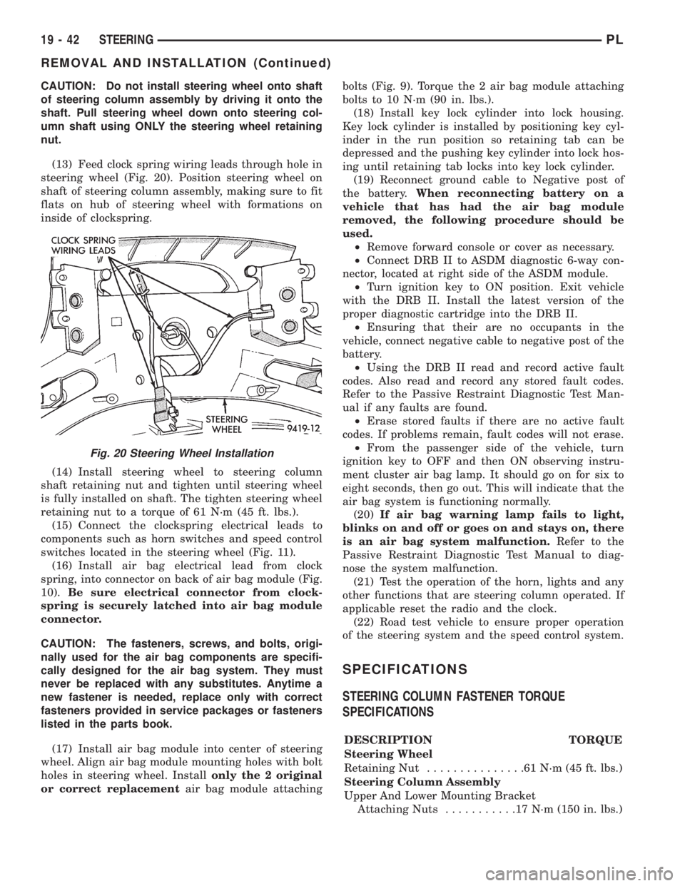
(13) Feed clock spring wiring leads through hole in
steering wheel (Fig. 20). Position steering wheel on
shaft of steering column assembly, making sure to fit
flats on hub of steering wheel with formations on
inside of clockspring.
(14) Install steering wheel to steering column
shaft retaining nut and tighten until steering wheel
is fully installed on shaft. The tighten steering wheel
retaining nut to a torque of 61 N´m (45 ft. lbs.).
(15) Connect the clockspring electrical leads to
components such as horn switches and speed control
switches located in the steering wheel (Fig. 11).
(16) Install air bag electrical lead from clock
spring, into connector on back of air bag module (Fig.
10).Be sure electrical connector from clock-
spring is securely latched into air bag module
connector.
CAUTION: The fasteners, screws, and bolts, origi-
nally used for the air bag components are specifi-
cally designed for the air bag system. They must
never be replaced with any substitutes. Anytime a
new fastener is needed, replace only with correct
fasteners provided in service packages or fasteners
listed in the parts book.
(17) Install air bag module into center of steering
wheel. Align air bag module mounting holes with bolt
holes in steering wheel. Installonly the 2 original
or correct replacementair bag module attachingbolts (Fig. 9). Torque the 2 air bag module attaching
bolts to 10 N´m (90 in. lbs.).
(18) Install key lock cylinder into lock housing.
Key lock cylinder is installed by positioning key cyl-
inder in the run position so retaining tab can be
depressed and the pushing key cylinder into lock hos-
ing until retaining tab locks into key lock cylinder.
(19) Reconnect ground cable to Negative post of
the battery.When reconnecting battery on a
vehicle that has had the air bag module
removed, the following procedure should be
used.
²Remove forward console or cover as necessary.
²Connect DRB II to ASDM diagnostic 6-way con-
nector, located at right side of the ASDM module.
²Turn ignition key to ON position. Exit vehicle
with the DRB II. Install the latest version of the
proper diagnostic cartridge into the DRB II.
²Ensuring that their are no occupants in the
vehicle, connect negative cable to negative post of the
battery.
²Using the DRB II read and record active fault
codes. Also read and record any stored fault codes.
Refer to the Passive Restraint Diagnostic Test Man-
ual if any faults are found.
²Erase stored faults if there are no active fault
codes. If problems remain, fault codes will not erase.
²From the passenger side of the vehicle, turn
ignition key to OFF and then ON observing instru-
ment cluster air bag lamp. It should go on for six to
eight seconds, then go out. This will indicate that the
air bag system is functioning normally.
(20)If air bag warning lamp fails to light,
blinks on and off or goes on and stays on, there
is an air bag system malfunction.Refer to the
Passive Restraint Diagnostic Test Manual to diag-
nose the system malfunction.
(21) Test the operation of the horn, lights and any
other functions that are steering column operated. If
applicable reset the radio and the clock.
(22) Road test vehicle to ensure proper operation
of the steering system and the speed control system.
SPECIFICATIONS
STEERING COLUMN FASTENER TORQUE
SPECIFICATIONS
DESCRIPTION TORQUE
Steering Wheel
Retaining Nut...............61N´m(45ft.lbs.)
Steering Column Assembly
Upper And Lower Mounting Bracket
Attaching Nuts...........17N´m(150 in. lbs.)
Fig. 20 Steering Wheel Installation
19 - 42 STEERINGPL
REMOVAL AND INSTALLATION (Continued)
Page 947 of 1200
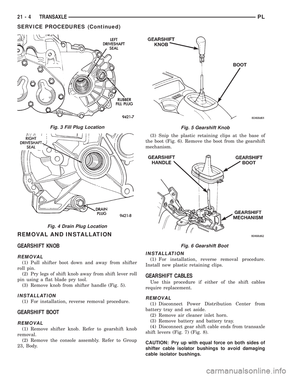
REMOVAL AND INSTALLATION
GEARSHIFT KNOB
REMOVAL
(1) Pull shifter boot down and away from shifter
roll pin.
(2) Pry legs of shift knob away from shift lever roll
pin using a flat blade pry tool.
(3) Remove knob from shifter handle (Fig. 5).
INSTALLATION
(1) For installation, reverse removal procedure.
GEARSHIFT BOOT
REMOVAL
(1) Remove shifter knob. Refer to gearshift knob
removal.
(2) Remove the console assembly. Refer to Group
23, Body.(3) Snip the plastic retaining clips at the base of
the boot (Fig. 6). Remove the boot from the gearshift
mechanism.
INSTALLATION
(1) For installation, reverse removal procedure.
Install new plastic retaining clips.
GEARSHIFT CABLES
Use this procedure if either of the shift cables
require replacement.
REMOVAL
(1) Disconnect Power Distribution Center from
battery tray and set aside.
(2) Remove air cleaner inlet horn.
(3) Remove battery and battery tray.
(4) Disconnect gear shift cable ends from transaxle
shift levers (Fig. 7) (Fig. 8).
CAUTION: Pry up with equal force on both sides of
shifter cable isolator bushings to avoid damaging
cable isolator bushings.
Fig. 5 Gearshift Knob
Fig. 6 Gearshift Boot
Fig. 3 Fill Plug Location
Fig. 4 Drain Plug Location
21 - 4 TRANSAXLEPL
SERVICE PROCEDURES (Continued)
Page 1200 of 1200
GROUP TAB LOCATOR
INIntroduction
INaIntroduction
0Lubrication and Maintenance
2Suspension
3Differential and Driveline
5Brakes
6Clutch
6aClutch
7Cooling
8ABattery
8BStarting
8CCharging System
8CaCharging System
8DIgnition System
8EInstrument Panel and Systems
8EaInstrument Panel and Systems
8FAudio System
8GHorns
8HVehicle Speed Control System
8HaVehicle Speed Control System
8JTurn Signal and Flashers
8KWindshield Wipers and Washers
8KaWindshield Wipers and Washers
8LLamps
8LaLamps
8MRestraint System
8NElectrically Heated Systems
8NaElectrically Heated Systems
8PPower Door Locks
8QaImmobilizer System
8SPower Windows
8TPower Mirrors
8TaPower Mirrors
8UChime Warning/Reminder System
8WWiring Diagrams - LHD and RHD
9Engine
9aEngine
11Exhaust System and Intake Manifold
11aExhaust System and Intake Manifold
13Frame and Bumpers
13aFrame and Bumpers
14Fuel System
14aFuel System - 1.8L Engine
19Steering
19aSteering
21Transaxle
21aTransaxle
22Tires and Wheels
23Body
24Heating and Air Conditioning
25Emission Control Systems
25aEmission Control System - 1.8L Engine