Page 1449 of 3115
DI3CE-03
I26015
Cowl Side J/B LH
� IGN FuseECM Engine Room R/B
� EFI Fuse
DLC3
Transponder Key
Amprifier w/coil
Transponder Key ECU DI-1008
- DIAGNOSTICSENGINE IMMOBILISER SYSTEM
1201 Author�: Date�:
2004 LAND CRUISER (RM1071U)
PARTS LOCATION
Page 1453 of 3115

PROBLEM SYMPTOMS TABLE
SymptomSuspect AreaSee page
Immobiliser is not set.
(Engine starts wit")
DI1AP-34
- DIAGNOSTICSENGINE IMMOBILISER SYSTEM
DI-1013
1206 Author�: Date�:
2004 LAND CRUISER (RM1071U)
PROBLEM SYMPTOMS TABLE
SymptomSuspect AreaSee page
Immobiliser is not set.
(Engine starts with key codes other than the registered key code.)1. Transponder key ECUIN-36
Engine does not start.
1. Key
2. Wire harness
3. Transponder key coil
4. Amplifier
5. Transponder key ECU
6. ECM*1
IN-36
BE-196
IN-36
Security indicator is always ON.
1. Multi-display (security indicator)
2. Wire harness
3. Transponder key ECU*2
IN-36
IN-36
Security indicator is always ON.
(Although code has been registered in the automatic registration
mode, indicator is not OFF.)1. Wire harness
2. Transponder key amplifier with coil
3. Transponder key ECUIN-36
BE-196
IN-36
Security indicator is OFF.
(When DTC of immobiliser is output)1. Wire harness
2. Transponder key amplifier with coil
3. Transponder key ECUIN-36
BE-196
IN-36
Security indicator is OFF.
(When DTC of immobiliser is not output)
1. Multi-display (security indicator)
2. Diagnosis circuit
3. Wire harness
4. Transponder key ECU
IN-36
IN-36
Security indicator is abnormally blinking.1. Wire harness
2. Transponder key ECUIN-36
IN-36
No code is output.1. Power source circuit
2. Transponder key ECUDI-1031
IN-36
*1 : Check that the key which did not start the engine has been registered and that it is possible to start with
other already registered key.
*2 : Finish the automatic registration mode because the mode might still remain.
Page 1794 of 3115

COMPRESSION
INSPECTION
HINT:
If there is a lack of power, excessive oil consump")
EM0KR-09
A04458
Compression
Gauge
- ENGINE MECHANICALCOMPRESSION
EM-3
1576 Author�: Date�:
2004 LAND CRUISER (RM1071U)
COMPRESSION
INSPECTION
HINT:
If there is a lack of power, excessive oil consumption or poor fuel
economy, measure the compression pressure.
1. WARM UP AND STOP ENGINE
Allow the engine to warm up to the normal operating tempera-
ture.
2. REMOVE SPARK PLUGS
(See page IG-1)
3. CHECK CYLINDER COMPRESSION PRESSURE
(a) Insert a compression gauge into the spark plug hole.
(b) Fully open the throttle.
(c) While cranking the engine, measure the compression
pressure.
HINT:
Always use a fully charged battery to obtain the engine speed
at 250 rpm or more.
(d) Repeat steps (a) to (c) for each cylinder.
NOTICE:
This measurement must be done as quickly as possible.
Compression pressure:
1,324 kPa (13.5 kgf/cm
2, 192 psi) or more
Minimum pressure:
981 kPa (10.0 kgf/cm
2, 142 psi)
Difference between each cylinder:
98 kPa (1.0 kgf/cm
2, 14 psi) or less
(e) If the cylinder compression in one or more cylinders is
lower than the specification, pour a small amount of en-
gine oil into the cylinder through the spark plug hole and
repeat steps (a) to (c) for the cylinders.
�If adding oil helps the compression, chances are
that the piston rings and/or cylinder bore are worn
or damage.
�If the pressure stays low, a valve may be sticking or
the seating is improper, or there may be leakage
past the gasket.
4. REINSTALL SPARK PLUGS
(See page IG-1)
Page 1795 of 3115

EM0E9-15
A05111
Engine Mounting Bracket
Oil Pump
Crankshaft
Front Oil
Seal
Crankshaft Position
Sensor Connector
No.1 Oil Pan
Drain Plug
� Non-reusable part
� Precoated partEngine Wire
Oil StrainerEngine
Mounting
BracketStarter
Cable
Knock
Sensor 2
Connector Knock
Sensor 1Knock
Sensor 2
Engine Coolant Drain UnionStarter
No.2 Oil Pan Oil Pan Baffle Platex 8 Water Pump
� Gasket � O-Ring
Engine
Wire
Engine
Wire
CoverKnock
Sensor 1
Connector Engine Coolant
Drain Union
45 (450, 33)
36 (370, 27)
30.5 (310, 22)
15.5 (160, 11)
28 (290, 31)
x 5
Oil Pressure
Sender Gauge
Connector
7.5 (80, 66 in.´lbf)
7.5 (80, 66 in.´lbf)
7.5 (80, 66 in.´lbf)
N´m (kgf´cm, ft´lbf) : Specified torque �
�
x 20
Ground
Cable
Clamp
Engine Wire
Protector
� Tape
28 (290, 31)
� Gasket
7.5 (80, 66 in.´lbf)
28 (290, 31)
7.5 (80, 66 in.´lbf)
Water Bypass Pipe
Oil Cooler Pipe
Bracket for A/T
7.5 (80, 66 in.´lbf)
� O-Ring
Starter
Connector
� Gasket
EM-86
- ENGINE MECHANICALCYLINDER BLOCK
1659 Author�: Date�:
2004 LAND CRUISER (RM1071U)
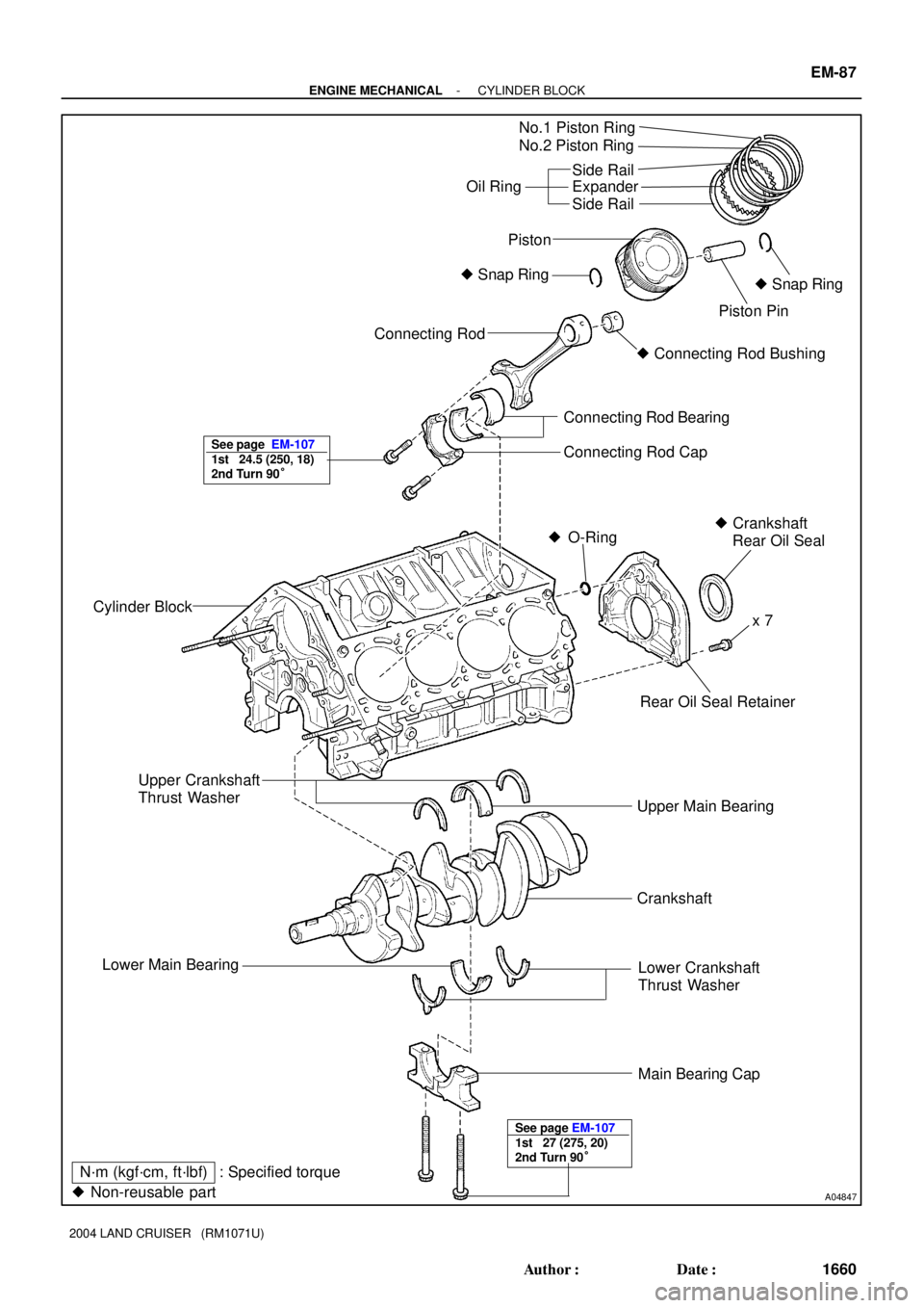
CYLINDER BLOCK
COMPONENTS
Page 1796 of 3115
A04847
No.1 Piston Ring
No.2 Piston Ring
Oil RingSide Rail
Expander
Side Rail
Connecting Rod
Connecting Rod Bearing
Connecting Rod Cap
Cylinder Block� Snap Ring
Piston Pin
� Crankshaft
Rear Oil Seal � O-Ring
Rear Oil Seal Retainer
Upper Main Bearing� Snap Ring Piston
Upper Crankshaft
Thrust Washer
Lower Main Bearing
Lower Crankshaft
Thrust Washer
Main Bearing Cap
� Non-reusable partx 7
Crankshaft
N´m (kgf´cm, ft´lbf) : Specified torque� Connecting Rod Bushing
See page EM-107
1st 24.5 (250, 18)
2nd Turn 90°
See page EM-107
1st 27 (275, 20)
2nd Turn 90°
- ENGINE MECHANICALCYLINDER BLOCK
EM-87
1660 Author�: Date�:
2004 LAND CRUISER (RM1071U)
Page 1797 of 3115

DISASSEMBLY
1. INSTALL ENGINE TO ENGINE")
EM0L6-03
A05112
Pull
Wire
Clamp
O-Ring
A05110
LH Side
A05109
RH Side EM-88
- ENGINE MECHANICALCYLINDER BLOCK
1661 Author�: Date�:
2004 LAND CRUISER (RM1071U)
DISASSEMBLY
1. INSTALL ENGINE TO ENGINE STAND
2. REMOVE TIMING BELT AND PULLEYS
(See page EM-15)
3. REMOVE CYLINDER HEAD (See page EM-35)
4. REMOVE WATER BYPASS PIPE
(a) Disconnect the wire clamp (for knock sensor 1, 2) from the
bracket of the water bypass pipe.
(b) Remove the bolt.
(c) Pull out the water bypass pipe from the water pump.
(d) Remove the O-ring from the water bypass pipe.
5. REMOVE STARTER (See page ST-5)
6. REMOVE KNOCK SENSORS (See page SF-55)
7. DISCONNECT ENGINE WIRE FROM LH SIDE OF CYL-
INDER BLOCK
(a) Remove the 2 bolts and the engine wire cover from the LH
side of the cylinder block.
(b) Remove the bolt, disconnect the bracket on the engine
wire from the cylinder block.
8. DISCONNECT ENGINE WIRE FROM RH SIDE OF CYL-
INDER BLOCK
Remove the 2 bolts, and disconnect the 2 brackets on the en-
gine wire from the cylinder block.
9. REMOVE OIL COOLER PIPE BRACKET FOR A/T
Remove the bolt and bracket.
10. REMOVE ENGINE MOUNTING BRACKETS
Remove the 4 bolts and the mounting bracket. Remove the 2
mounting brackets
11. REMOVE WATER PUMP (See page CO-6)
12. REMOVE NO.2 OIL PAN (See page LU-8)
13. REMOVE OIL PAN BAFFLE PLATE
14. REMOVE NO.1 OIL PAN (See page LU-8)
15. REMOVE OIL STRAINER
16. REMOVE OIL PUMP (See page LU-8)
17. REMOVE ENGINE COOLANT DRAIN UNIONS
Remove the 2 drain unions.
Page 1798 of 3115

18. REMOVE REAR OIL SEAL RETAINER
(a) Remove the 7 bolts.
(b) Using a screwdr")
A05086
pry
A05100
A05104
A05105
- ENGINE MECHANICALCYLINDER BLOCK
EM-89
1662 Author�: Date�:
2004 LAND CRUISER (RM1071U)
18. REMOVE REAR OIL SEAL RETAINER
(a) Remove the 7 bolts.
(b) Using a screwdriver, ply off the oil seal retainer and the
main bearing cap with a screwdriver.
(c) Remove the O-ring.
19. CHECK CONNECTING ROD THRUST CLEARANCE
Using a dial indicator, measure the thrust clearance while mov-
ing the connecting rod back an a forth.
Standard thrust clearance:
0.160 - 0.290 mm (0.0063 - 0.0138 in.)
Maximum thrust clearance: 0.35 mm (0.0138 in.)
If the thrust clearance is greater than the maximum, replace the
connecting rod assembly(s). If necessary, replace the crank-
shaft.
Connecting rod thickness:
22.880 - 22.920 mm (0.9008 - 0.9024 in.)
20. REMOVE CONNECTING ROD CAPS AND CHECK
OIL CLEARANCE
(a) Check the matchmarks on the connecting rod and cap to
ensure correct reassembly.
(b) Remove the 2 connecting rod cap bolts.
(c) Using the 2 removed connecting rod cap bolts, remove
the connecting rod cap and the lower bearing by wiggling
the connecting rod cap right and left.
HINT:
Keep the lower bearing inserted with the connecting rod cap.
(d) Clean the crank pin and the bearing.
(e) Check the crank pin and the bearing for pitting and
scratches.
If the crank pin or the bearing is damaged, replace the bearings.
If necessary, replace the crankshaft.
Page 1799 of 3115

A05102
Plastigage
A05101
A05103
A05852
A05087A05853A05175
Number
Mark
Number
Mark
Number
Mark No.1
No.2No.3No.4
Connecting rod cap
Crankshaft
Use bearingNumber mark1
2
34 76 1
21
1 2
1
32
23
12
33
24
13
344
23
5
EXAMPLE:
Connecting rod cap º3º + Crankshaft º1º
= Total number 4 (Use bearing º4º) EM-90
- ENGINE MECHANICALCYLINDER BLOCK
1663 Author�: Date�:
2004 LAND CRUISER (RM1071U)
(f) Lay a strip of plastigage across the crank pin.
(g) Install the connecting rod cap with the 2 bolts.
(See page EM-107)
NOTICE:
Do not turn the crankshaft.
(h) Remove the 2 bolts, the connecting rod cap and the lower
bearing. (See procedure (b) and (c) above)
(i) Measure the plastigage at its widest point.
Standard oil clearance:
0.027 - 0.053 mm (0.0011 - 0.0021 in.)
Maximum oil clearance: 0.065 mm (0.0026 in.)
If the oil clearance is greater than the maximum, replace the
bearings. If necessary, replace the crankshaft.
HINT:
If using a standard bearing, replace it with the one having the
same number. If the number of the bearing cannot be deter-
mined, sum up the numbers imprinted on the connecting rod
cap and the crankshaft, then select the one with the same num-
ber as the total. There are 6 sizes of standard bearings, marked
º2º, º3º, º4º, º5º, º6º and º7º.