Page 1399 of 3115

DI-40
- DIAGNOSTICSENGINE
233 Author�: Date�:
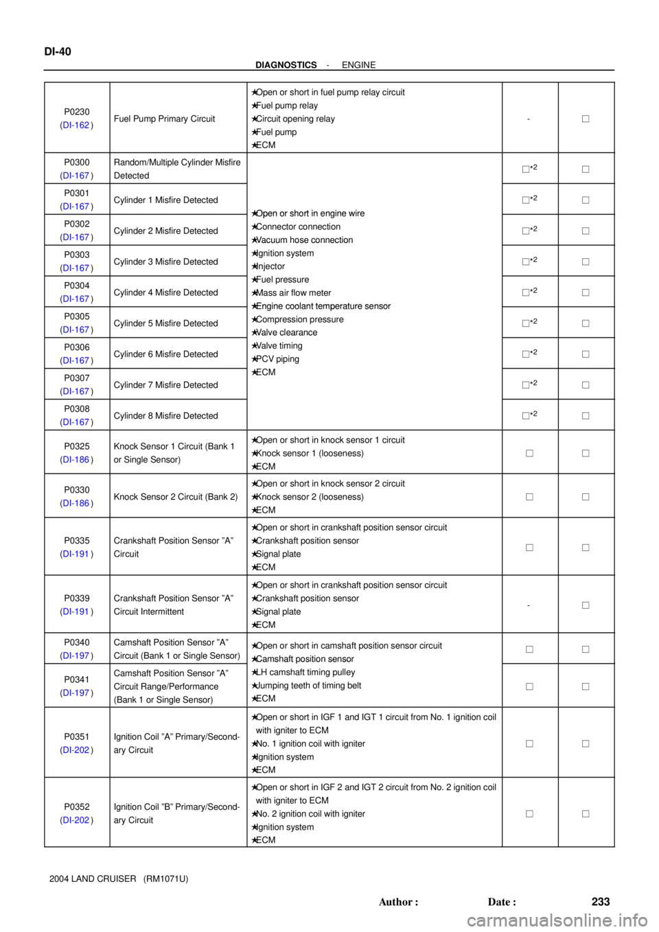
2004 LAND CRUISER (RM1071U)P0230
(DI-162)
Fuel Pump Primary Circuit
�Open or short in fuel pump relay circuit
�Fuel pump relay
�Circuit opening relay
�Fuel pump
�ECM
-�
P0300
(DI-167)Random/Multiple Cylinder Misfire
Detected�*2�
P0301
(DI-167)Cylinder 1 Misfire Detected
�Open or short in engine wire
�*2�
P0302
(DI-167)Cylinder 2 Misfire Detected
�Open or short in engine wire
�Connector connection
�Vacuum hose connection
�*2�
P0303
(DI-167)Cylinder 3 Misfire Detected
�Vacuum hose connection
�Ignition system
�Injector�*2�
P0304
(DI-167)Cylinder 4 Misfire Detected
�Fuel pressure
�Mass air flow meter
�Engine coolant temperature sensor
�*2�
P0305
(DI-167)Cylinder 5 Misfire Detected
�Engine coolant temperature sensor
�Compression pressure
�Valve clearance
�*2�
P0306
(DI-167)Cylinder 6 Misfire Detected
�Valve clearance
�Valve timing
�PCV piping�*2�
P0307
(DI-167)Cylinder 7 Misfire Detected
�ECM
�*2�
P0308
(DI-167)Cylinder 8 Misfire Detected�*2�
P0325
(DI-186)Knock Sensor 1 Circuit (Bank 1
or Single Sensor)�Open or short in knock sensor 1 circuit
�Knock sensor 1 (looseness)
�ECM
��
P0330
(DI-186)Knock Sensor 2 Circuit (Bank 2)
�Open or short in knock sensor 2 circuit
�Knock sensor 2 (looseness)
�ECM
��
P0335
(DI-191)Crankshaft Position Sensor ºAº
Circuit
�Open or short in crankshaft position sensor circuit
�Crankshaft position sensor
�Signal plate
�ECM
��
P0339
(DI-191)Crankshaft Position Sensor ºAº
Circuit Intermittent
�Open or short in crankshaft position sensor circuit
�Crankshaft position sensor
�Signal plate
�ECM
-�
P0340
(DI-197)Camshaft Position Sensor ºAº
Circuit (Bank 1 or Single Sensor)�Open or short in camshaft position sensor circuit
�Camshaft position sensor��
P0341
(DI-197)Camshaft Position Sensor ºAº
Circuit Range/Performance
(Bank 1 or Single Sensor)
�Camshaft osition sensor
�LH camshaft timing pulley
�Jumping teeth of timing belt
�ECM
��
P0351
(DI-202)Ignition Coil ºAº Primary/Second-
ary Circuit
�Open or short in IGF 1 and IGT 1 circuit from No. 1 ignition coil
with igniter to ECM
�No. 1 ignition coil with igniter
�Ignition system
�ECM
��
P0352
(DI-202)Ignition Coil ºBº Primary/Second-
ary Circuit
�Open or short in IGF 2 and IGT 2 circuit from No. 2 ignition coil
with igniter to ECM
�No. 2 ignition coil with igniter
�Ignition system
�ECM
��
Page 1400 of 3115

- DIAGNOSTICSENGINE
DI-41
234 Author�: Date�:
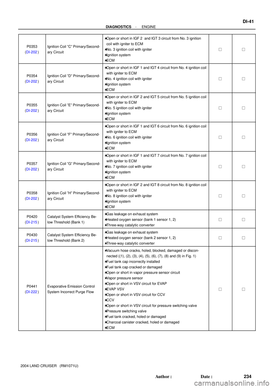
2004 LAND CRUISER (RM1071U)P0353
(DI-202)
Ignition Coil ºCº Primary/Second-
ary Circuit
�Open or short in IGF 2 and IGT 3 circuit from No. 3 ignition
coil with igniter to ECM
�No. 3 ignition coil with igniter
�Ignition system
�ECM
��
P0354
(DI-202)Ignition Coil ºDº Primary/Second-
ary Circuit
�Open or short in IGF 1 and IGT 4 circuit from No. 4 ignition coil
with igniter to ECM
�No. 4 ignition coil with igniter
�Ignition system
�ECM
��
P0355
(DI-202)Ignition Coil ºEº Primary/Second-
ary Circuit
�Open or short in IGF 2 and IGT 5 circuit from No. 5 ignition coil
with igniter to ECM
�No. 5 ignition coil with igniter
�Ignition system
�ECM
��
P0356
(DI-202)Ignition Coil ºFº Primary/Second-
ary Circuit
�Open or short in IGF 1 and IGT 6 circuit from No. 6 ignition coil
with igniter to ECM
�No. 6 ignition coil with igniter
�Ignition system
�ECM
��
P0357
(DI-202)Ignition Coil ºGº Primary/Second-
ary Circuit
�Open or short in IGF 1 and IGT 7 circuit from No. 7 ignition coil
with igniter to ECM
�No. 7 ignition coil with igniter
�Ignition system
�ECM
��
P0358
(DI-202)Ignition Coil ºHº Primary/Second-
ary Circuit
�Open or short in IGF 2 and IGT 8 circuit from No. 8 ignition coil
with igniter to ECM
�No. 8 ignition coil with igniter
�Ignition system
�ECM
��
P0420
(DI-215)Catalyst System Efficiency Be-
low Threshold (Bank 1)�Gas leakage on exhaust system
�Heated oxygen sensor (bank 1 sensor 1, 2)
�Three-way catalytic converter
��
P0430
(DI-215)Catalyst System Efficiency Be-
low Threshold (Bank 2)�Gas leakage on exhaust system
�Heated oxygen sensor (bank 2 sensor 1, 2)
�Three-way catalytic converter
��
P0441
(DI-222)Evaporative Emission Control
System Incorrect Purge Flow
�Vacuum hose cracks, holed, blocked, damaged or discon-
nected ((1), (2), (3), (4), (5), (6), (7), (8) and (9) in Fig. 1)
�Fuel tank cap incorrectly installed
�Fuel tank cap cracked or damaged
�Open or short in vapor pressure sensor circuit
�Vapor pressure sensor
�Open or short in VSV circuit for EVAP
�EVAP VSV
�Open or short in VSV circuit for CCV
�CCV
�Open or short in VSV circuit for pressure switching valve
�Pressure switching valve
�Fuel tank cracked, holed or damaged
�Charcoal canister cracked, holed or damaged
�ECM
��
Page 1405 of 3115
DI1L5-18
A21338
Fuel Pump Resister Knock Sensor 2
Heated Oxygen Sensor
(Bank 1 Sensor 1) Heated Oxygen Sensor
(Bank 2 Sensor 1)VSV for EVAP
Combination Meter
Ignition Coil with Igniter
ECMKnock Sensor 1
Injector
Throttle Control
Motor and Sensor
Mass Air Flow Meter
Engine Coolant
Temperature Sensor
Camshaft
Position Sensor
Crankshaft
Position Sensor
VSV for CCV
Park/neutral Position Switch DLC3
Vapor Pressure Sensor VSV for
Pressure Switching Valve
Accelerator Pedal Assembly
(Accelerator Pedal Position Sensor)
Cowl Side J/B LH:
� STOP Fuse
� EFI or ECD No. 2 Fuse
Engine Room R/B and J/B:
� Circuit Opening Relay
� Fuel Pump Relay
� EFI or ECD Relay
� STARTER Relay
� EFI or ECD No. 1 Fuse
� ECTS Fuse
- DIAGNOSTICSENGINE
DI-45
238 Author�: Date�:
2004 LAND CRUISER (RM1071U)
PARTS LOCATION
Page 1414 of 3115
- DIAGNOSTICSENGINE
DI-1 1
204 Author�: Date�:
4 Check air filter.
PREPARATION:
Remove the air filter.
CHECK:
Visual check that the air filter is not excessively dirty or oily.
NG Repair or replace
air filter.
OK
5 Check idle speed.
PREPARATION:
(a) Warm up the engine to the normal operating temperature.
(b) Switch off all the accessories.
(c) Switch off the A/C.
(d) Shift the transmission into the N position.
(e) Connect the OBD II scan tool or hand-held tester to the DLC3 of the vehicle.
CHECK:
Use CURRENT DATA to check the idle speed.
OK:
Idle speed:
650 to 750 rpm
NG Proceed to problem symptoms table on page
DI-48.
OK
Page 1416 of 3115
A19431
A19884
- DIAGNOSTICSENGINE
DI-13
206 Author�: Date�:
7 Check for spark.
PREPARATION:
(a) Disconnect the ignition coil.
(b) Remove the spark plug.
(c) Install the spark plug to the ignition coil.
(d) Disconnect the injector connector.
(e) Ground the spark plug.
CHECK:
Check if spark occurs while the engine is being cranked.
NOTICE:
To prevent excess fuel from being injected from the injec-
tors during this test, don't crank the engine for more than
5 to 10 seconds at a time.
NG Proceed to page IG-1 and continue to trouble-
shoot.
OK
Proceed to problem symptoms table on page
DI-48.
Page 1421 of 3115
![TOYOTA LAND CRUISER 1998 Factory Repair Manual DI-18
- DIAGNOSTICSENGINE
211 Author�: Date�:
TC/TE1
[Test Details]
Connect the TC and TE1.
ON or OFFSwitch to the same state as
the connection between
terminal TC and TE1.
FC IDL PROHBT
[Test Detail TOYOTA LAND CRUISER 1998 Factory Repair Manual DI-18
- DIAGNOSTICSENGINE
211 Author�: Date�:
TC/TE1
[Test Details]
Connect the TC and TE1.
ON or OFFSwitch to the same state as
the connection between
terminal TC and TE1.
FC IDL PROHBT
[Test Detail](/manual-img/14/57459/w960_57459-1420.png)
DI-18
- DIAGNOSTICSENGINE
211 Author�: Date�:
TC/TE1
[Test Details]
Connect the TC and TE1.
ON or OFFSwitch to the same state as
the connection between
terminal TC and TE1.
FC IDL PROHBT
[Test Details]
Control the idle fuel cut prohibit.
ON or OFF
-
9. DEFINITION OF TERMS
TermDefinition
Monitor descriptionDescription of what the ECM monitors and how it detects malfunctions (monitoring purpose and its details).
Related DTCsDiagnostic code
Typical enabling condition
Preconditions that allow the ECM to detect malfunctions.
With all preconditions satisfied, the ECM sets the DTC when the monitored value(s) exceeds the malfunction
threshold(s).
Sequence of operation
The priority order that is applied to monitoring, if multiple sensors and components are used to detect the malfunc-
tion.
When a sensor is being monitored, the next sensor or component will not be monitored until the sensor monitoring
is finished.
Required sensor/compo-
nentsThe sensors and components that are used by the ECM to detect malfunctions.
Frequency of operation
The number of times that the ECM checks for malfunctions per driving cycle.
ºOnce per driving cycleº means that the ECM detects the malfunction only one time during a single driving cycle.
ºContinuousº means that the ECM detects malfunction every time an enabling condition is met.
DurationThe minimum time that the ECM must sense a continuous deviation in the monitored value(s) before setting a
DTC. This timing begins after the ºtypical enabling conditionsº are met.
Malfunction thresholdsBeyond this value, the ECM will conclude that there is a malfunction and set a DTC.
MIL operation
MIL illumination timing after a defect is detected.
ºImmediatelyº means that the ECM illuminates MIL the instant the ECM determines that there is a malfunction.
º2 driving cycleº means that the ECM illuminates MIL if the same malfunction is detected again in the 2nd driving
cycle.
10. TOYOTA/LEXUS PART AND SYSTEM NAME LIST
This reference list indicates the part names used in this manual along with their definitions.
TOYOTA/LEXUS nameDefinition
Toyota HCAC system, Hydro-carbon Adsorptive Catalyst
(HCAC) system, HC adsorptive three-way catalystHC adsorptive three-way catalytic converter
Variable Valve Timing sensor, VVT sensorCamshaft position sensor
Variable valve timing system, VVT systemCamshaft timing control system
Camshaft timing oil control valve, Oil control valve, OCV,
VVT, VSVCamshaft timing oil control valve
Variable timing and lift, VVTLCamshaft timing and lift control
Crankshaft position sensor ºAºCrankshaft position sensor
Engine speed sensorCrankshaft position sensor
THAIntake air temperature
Knock control moduleEngine knock control module
Knock sensorEngine knock sensor
Mass or volume air flow circuitMass air flow sensor circuit
Vacuum sensorManifold air pressure sensor
Internal control module, Control module, Engine control
ECU, PCMPower train control module
FC idleDeceleration fuel cut
Page 1445 of 3115
- DIAGNOSTICSENGINE IMMOBILISER SYSTEM
DI-1017
1210 Author�: Date�:
2004 LAND CRUISER (RM1071U)
DTC B2784 TRANSPONDER KEY COIL MALFUNCTION
CIRCUIT DESCRIPTION
This DTC is output when short or open of the key coil built in the transponder key amplifier is detected.
DTC No.DTC Detecting ConditionTrouble Area
B2784Transponder key coil malfunctionTransponder key amplifier with coil
INSPECTION PROCEDURE
Replace key.
DIB5Y-01
Page 1447 of 3115

DI1AM-29
- DIAGNOSTICSENGINE IMMOBILISER SYSTEM
DI-1007
1200 Author�: Date�:
2004 LAND CRUISER (RM1071U)
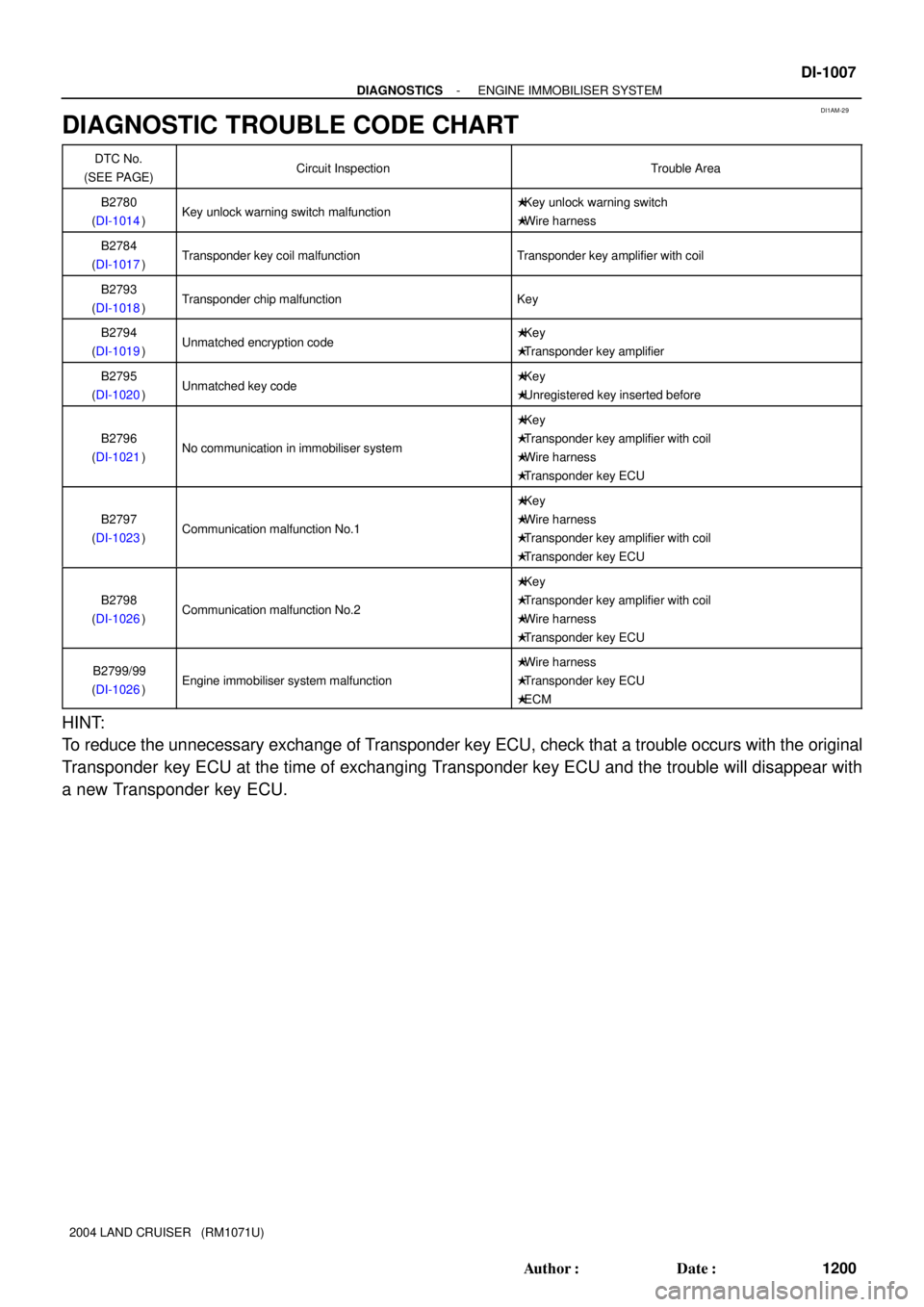
DIAGNOSTIC TROUBLE CODE CHART
DTC No.
(SEE PAGE)Circuit InspectionTrouble Area
B2780
(DI-1014)Key unlock warning switch malfunction�Key unlock warning switch
�Wire harness
B2784
(DI-1017)Transponder key coil malfunctionTransponder key amplifier with coil
B2793
(DI-1018)Transponder chip malfunctionKey
B2794
(DI-1019)Unmatched encryption code�Key
�Transponder key amplifier
B2795
(DI-1020)Unmatched key code�Key
�Unregistered key inserted before
B2796
(DI-1021)No communication in immobiliser system
�Key
�Transponder key amplifier with coil
�Wire harness
�Transponder key ECU
B2797
(DI-1023)Communication malfunction No.1
�Key
�Wire harness
�Transponder key amplifier with coil
�Transponder key ECU
B2798
(DI-1026)Communication malfunction No.2
�Key
�Transponder key amplifier with coil
�Wire harness
�Transponder key ECU
B2799/99
(DI-1026)Engine immobiliser system malfunction
�Wire harness
�Transponder key ECU
�ECM
HINT:
To reduce the unnecessary exchange of Transponder key ECU, check that a trouble occurs with the original
Transponder key ECU at the time of exchanging Transponder key ECU and the trouble will disappear with
a new Transponder key ECU.