F17185
SR0MO-08
F12855
SST
Fulcrum
Length
F04791
Stopper
- STEERINGPOWER STEERING GEAR
SR-65
2274 Author�: Date�:
2004 LAND CRUISER (RM1071U)
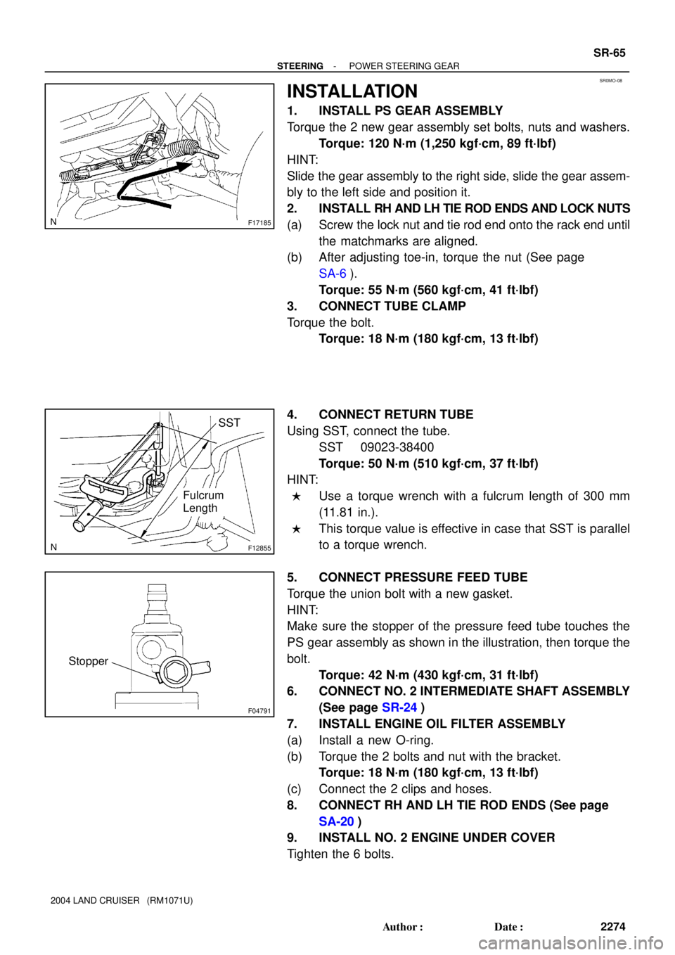
INSTALLATION
1. INSTALL PS GEAR ASSEMBLY
Torque the 2 new gear assembly set bolts, nuts and washers.
Torque: 120 N´m (1,250 kgf´cm, 89 ft´lbf)
HINT:
Slide the gear assembly to the right side, slide the gear assem-
bly to the left side and position it.
2. INSTALL RH AND LH TIE ROD ENDS AND LOCK NUTS
(a) Screw the lock nut and tie rod end onto the rack end until
the matchmarks are aligned.
(b) After adjusting toe-in, torque the nut (See page
SA-6).
Torque: 55 N´m (560 kgf´cm, 41 ft´lbf)
3. CONNECT TUBE CLAMP
Torque the bolt.
Torque: 18 N´m (180 kgf´cm, 13 ft´lbf)
4. CONNECT RETURN TUBE
Using SST, connect the tube.
SST 09023-38400
Torque: 50 N´m (510 kgf´cm, 37 ft´lbf)
HINT:
�Use a torque wrench with a fulcrum length of 300 mm
(11.81 in.).
�This torque value is effective in case that SST is parallel
to a torque wrench.
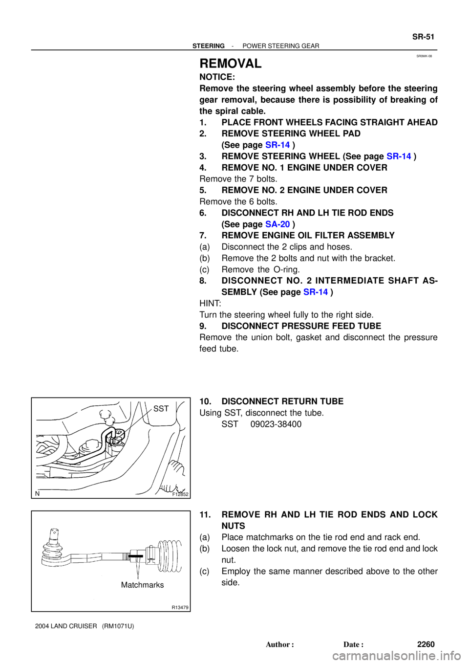
5. CONNECT PRESSURE FEED TUBE
Torque the union bolt with a new gasket.
HINT:
Make sure the stopper of the pressure feed tube touches the
PS gear assembly as shown in the illustration, then torque the
bolt.
Torque: 42 N´m (430 kgf´cm, 31 ft´lbf)
6. CONNECT NO. 2 INTERMEDIATE SHAFT ASSEMBLY
(See page SR-24)
7. INSTALL ENGINE OIL FILTER ASSEMBLY
(a) Install a new O-ring.
(b) Torque the 2 bolts and nut with the bracket.
Torque: 18 N´m (180 kgf´cm, 13 ft´lbf)
(c) Connect the 2 clips and hoses.
8. CONNECT RH AND LH TIE ROD ENDS (See page
SA-20)
9. INSTALL NO. 2 ENGINE UNDER COVER
Tighten the 6 bolts.
SR0MK-08
F12852
SST
R13479
Matchmarks
- STEERINGPOWER STEERING GEAR
SR-51
2260 Author�: Date�:
2004 LAND CRUISER (RM1071U)
REMOVAL
NOTICE:
Remove the steering wheel assembly before the steering
gear removal, because there is possibility of breaking of
the spiral cable.
1. PLACE FRONT WHEELS FACING STRAIGHT AHEAD
2. REMOVE STEERING WHEEL PAD
(See page SR-14)
3. REMOVE STEERING WHEEL (See page SR-14)
4. REMOVE NO. 1 ENGINE UNDER COVER
Remove the 7 bolts.
5. REMOVE NO. 2 ENGINE UNDER COVER
Remove the 6 bolts.
6. DISCONNECT RH AND LH TIE ROD ENDS
(See page SA-20)
7. REMOVE ENGINE OIL FILTER ASSEMBLY
(a) Disconnect the 2 clips and hoses.
(b) Remove the 2 bolts and nut with the bracket.
(c) Remove the O-ring.
8. DISCONNECT NO. 2 INTERMEDIATE SHAFT AS-
SEMBLY (See page SR-14)
HINT:
Turn the steering wheel fully to the right side.
9. DISCONNECT PRESSURE FEED TUBE
Remove the union bolt, gasket and disconnect the pressure
feed tube.
10. DISCONNECT RETURN TUBE
Using SST, disconnect the tube.
SST 09023-38400
11. REMOVE RH AND LH TIE ROD ENDS AND LOCK
NUTS
(a) Place matchmarks on the tie rod end and rack end.
(b) Loosen the lock nut, and remove the tie rod end and lock
nut.
(c) Employ the same manner described above to the other
side.