Page 2454 of 3115
LU08X-06
B04612
LU-20
- LUBRICATIONOIL COOLER
1801 Author�: Date�:
2004 LAND CRUISER (RM1071U)
REMOVAL
1. DRAIN ENGINE COOLANT
2. REMOVE OIL FILTER (See page LU-2)
3. REMOVE OIL COOLER
(a) Disconnect the 2 oil cooler hoses from the oil cooler.
(b) Remove the union bolt, plate washer and the oil cooler.
(c) Remove the O-ring from the oil cooler.
Page 2455 of 3115
LU08P-07
B04470
B04791
RH No.3 Timing Belt Cover
LH No.3 Timing Belt CoverNo.2 Timing Belt Cover
Camshaft Position
Sensor Connector
Engine Wire
Drive Belt Idler PulleyTiming Belt
Fan Bracket
N´m (kgf´cm, ft´lbf) : Specified torqueOil Cooler Pipe
Timing Belt Tensioner Dust Boot
Cover Plate
39 (400,29)
245 (2,500, 181)
32 (330, 24)
16 (160, 12)
7.5 (80, 66 in.´lbf)
16 (160, 12)
Water Bypass
Hose
LU-4
- LUBRICATIONOIL PUMP
1785 Author�: Date�:
2004 LAND CRUISER (RM1071U)
OIL PUMP
COMPONENTS
Page 2460 of 3115
LU08S-05
B04454
B04455
Mark
B04456
B04457
B04458
LU-12
- LUBRICATIONOIL PUMP
1793 Author�: Date�:
2004 LAND CRUISER (RM1071U)
INSPECTION
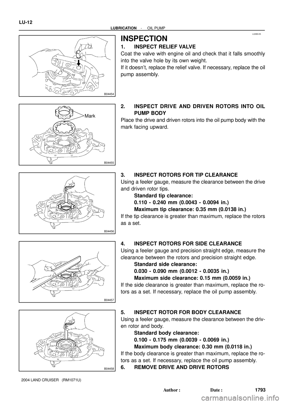
1. INSPECT RELIEF VALVE
Coat the valve with engine oil and check that it falls smoothly
into the valve hole by its own weight.
If it doesn't, replace the relief valve. If necessary, replace the oil
pump assembly.
2. INSPECT DRIVE AND DRIVEN ROTORS INTO OIL
PUMP BODY
Place the drive and driven rotors into the oil pump body with the
mark facing upward.
3. INSPECT ROTORS FOR TIP CLEARANCE
Using a feeler gauge, measure the clearance between the drive
and driven rotor tips.
Standard tip clearance:
0.110 - 0.240 mm (0.0043 - 0.0094 in.)
Maximum tip clearance: 0.35 mm (0.0138 in.)
If the tip clearance is greater than maximum, replace the rotors
as a set.
4. INSPECT ROTORS FOR SIDE CLEARANCE
Using a feeler gauge and precision straight edge, measure the
clearance between the rotors and precision straight edge.
Standard side clearance:
0.030 - 0.090 mm (0.0012 - 0.0035 in.)
Maximum side clearance: 0.15 mm (0.0059 in.)
If the side clearance is greater than maximum, replace the ro-
tors as a set. If necessary, replace the oil pump assembly.
5. INSPECT ROTOR FOR BODY CLEARANCE
Using a feeler gauge, measure the clearance between the driv-
en rotor and body.
Standard body clearance:
0.100 - 0.175 mm (0.0039 - 0.0069 in.)
Maximum body clearance: 0.30 mm (0.0118 in.)
If the body clearance is greater than maximum, replace the ro-
tors as a set. If necessary, replace the oil pump assembly.
6. REMOVE DRIVE AND DRIVE ROTORS
Page 2464 of 3115
B04486
Push New O-Ring
LU-18
- LUBRICATIONOIL PUMP
1799 Author�: Date�:
2004 LAND CRUISER (RM1071U)
�Parts must be assembled within 5 minutes of ap-
plication. Otherwise the material must be removed
and reapplied.
�Immediately remove nozzle from the tube and rein-
stall cap.
(c) Install the No.2 oil pan with the 20 bolts and 2 nuts. Uni-
formly tighten the bolts and nuts in several passes.
Torque: 7.5 N´m (80 kgf´cm, 66 in.´lbf)
HINT:
Use bolts 14 mm (0.55 in.) in length.
6. INSTALL CRANKSHAFT POSITION SENSOR
(See page IG-13)
7. INSTALL OIL FILTER, OIL COOLER AND FILTER
BRACKET ASSEMBLY
(a) Install the a new gasket to the oil filter bracket.
(b) Install the oil filter, oil cooler and filter bracket assembly
with the 2 bolts and nut.
Torque: 18 N´m (185 kgf´cm, 13 ft´lbf)
(c) Connect the oil pressure switch connector.
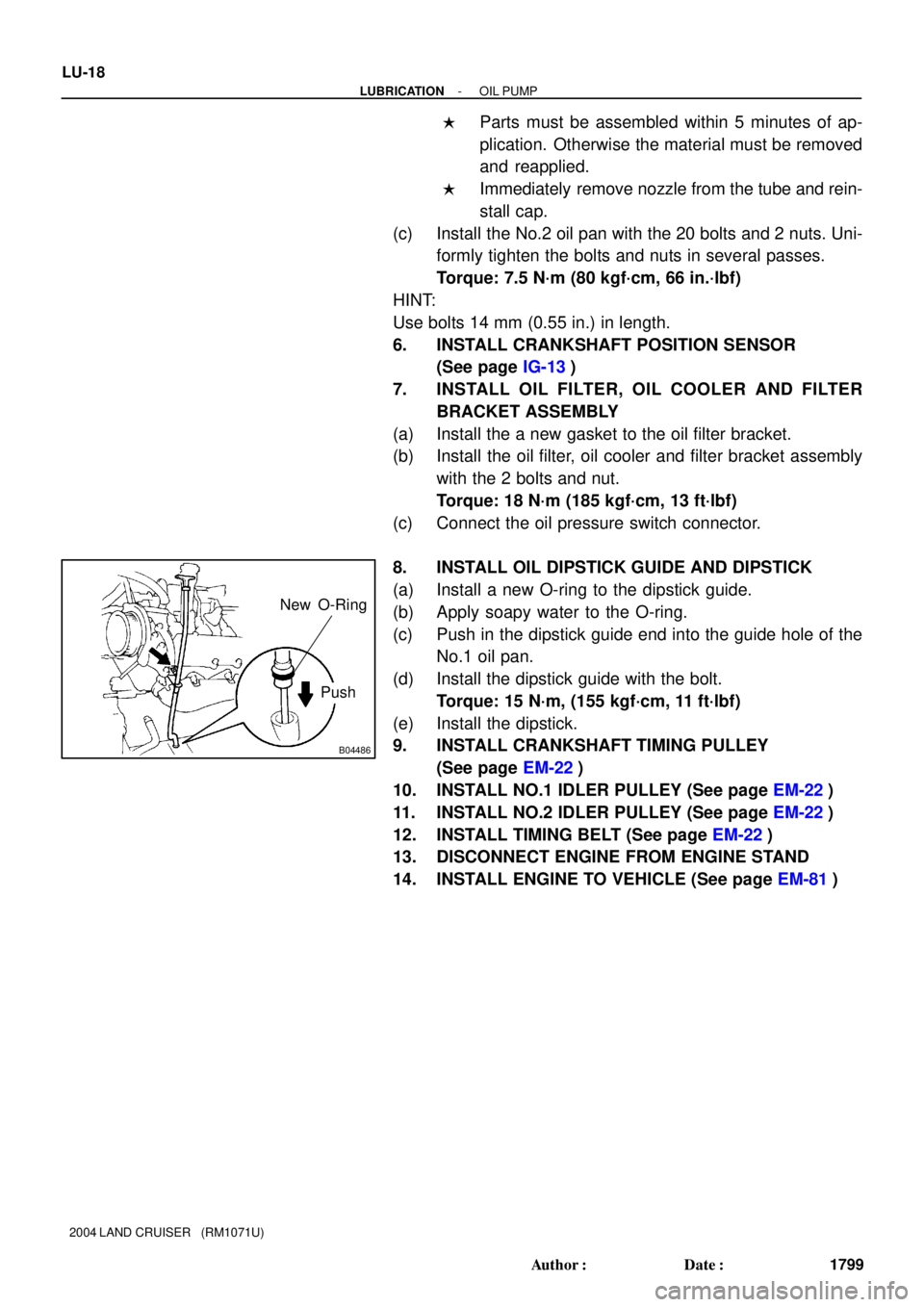
8. INSTALL OIL DIPSTICK GUIDE AND DIPSTICK
(a) Install a new O-ring to the dipstick guide.
(b) Apply soapy water to the O-ring.
(c) Push in the dipstick guide end into the guide hole of the
No.1 oil pan.
(d) Install the dipstick guide with the bolt.
Torque: 15 N´m, (155 kgf´cm, 11 ft´lbf)
(e) Install the dipstick.
9. INSTALL CRANKSHAFT TIMING PULLEY
(See page EM-22)
10. INSTALL NO.1 IDLER PULLEY (See page EM-22)
11. INSTALL NO.2 IDLER PULLEY (See page EM-22)
12. INSTALL TIMING BELT (See page EM-22)
13. DISCONNECT ENGINE FROM ENGINE STAND
14. INSTALL ENGINE TO VEHICLE (See page EM-81)
Page 2466 of 3115
LU08Q-08
B04486
Pull O-Ring
B03736
B04629
SST SST
LU-8
- LUBRICATIONOIL PUMP
1789 Author�: Date�:
2004 LAND CRUISER (RM1071U)
REMOVAL
HINT:
When repairing the oil pump, the oil pan and strainer should be
removed and cleaned.
1. REMOVE ENGINE FROM VEHICLE
(See page EM-77)
2. INSTALL ENGINE TO ENGINE STAND FOR DIS-
ASSEMBLY
3. REMOVE TIMING BELT (See page EM-15)
4. REMOVE NO.1 IDLER PULLEY (See page EM-15)
5. REMOVE NO.2 IDLER PULLEY (See page EM-15)
6. REMOVE CRANKSHAFT TIMING PULLEY
(See page EM-15)
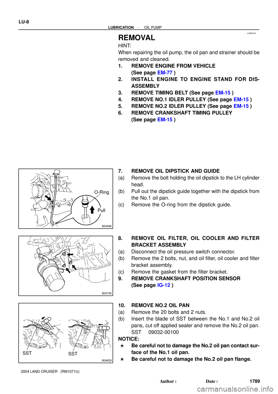
7. REMOVE OIL DIPSTICK AND GUIDE
(a) Remove the bolt holding the oil dipstick to the LH cylinder
head.
(b) Pull out the dipstick guide together with the dipstick from
the No.1 oil pan.
(c) Remove the O-ring from the dipstick guide.
8. REMOVE OIL FILTER, OIL COOLER AND FILTER
BRACKET ASSEMBLY
(a) Disconnect the oil pressure switch connector.
(b) Remove the 2 bolts, nut, and oil filter, oil cooler and filter
bracket assembly.
(c) Remove the gasket from the filter bracket.
9. REMOVE CRANKSHAFT POSITION SENSOR
(See page IG-12)
10. REMOVE NO.2 OIL PAN
(a) Remove the 20 bolts and 2 nuts.
(b) Insert the blade of SST between the No.1 and No.2 oil
pans, cut off applied sealer and remove the No.2 oil pan.
SST 09032-00100
NOTICE:
�Be careful not to damage the No.2 oil pan contact sur-
face of the No.1 oil pan.
�Be careful not to damage the No.2 oil pan flange.
Page 2475 of 3115
MA02S-01
MA-6
- MAINTENANCEENGINE
54 Author�: Date�:
2004 LAND CRUISER (RM1071U)
ENGINE
INSPECTION
HINT:
Inspect these items when the engine is cold.
1. REPLACE TIMING BELT (See page EM-15)
2. INSPECT VALVE CLEARANCE (See page EM-4)
3. INSPECT DRIVE BELT (See page CH-2)
4. REPLACE ENGINE OIL AND OIL FILTER (See page LU-2)
5. REPLACE ENGINE COOLANT (See page CO-2)
6. INSPECT EXHAUST PIPES AND MOUNTINGS
Visually inspect the pipes, hangers and connections for severe corrosion, leaks or damage.
7. REPLACE AIR CLEANER FILTER
Replace the air cleaner filter with a new one.
8. INSPECT FUEL LINES, CONNECTIONS AND FUEL VAPOR CONTROL VALVE (See page
EC-5)
Visually inspect the fuel lines for cracks, leakage loose connections, deformation or tank band looseness.
9. INSPECT GASKET IN FUEL TANK CAP (See page EC-5)
10. REPLACE SPARK PLUGS (See page IG-1)
11. California, Massachusetts and New York:
INSPECT CHARCOAL CANISTER (See page EC-5)
Page 2478 of 3115
MA02P-02
- MAINTENANCEOUTSIDE VEHICLE
MA-1
49 Author�: Date�:
2004 LAND CRUISER (RM1071U)
OUTSIDE VEHICLE
GENERAL MAINTENANCE
These are some maintenance and inspection items which are considered to be the owner's responsibility.
They can be done by the owner or they can have them done at a service shop. These items include those
which should be checked on a daily basis, those which, in most cases, do not require (special) tools and
those which are considered to be reasonable for the owner to do. Items and procedures for general mainte-
nance are as follows.
1. GENERAL NOTES
�Maintenance items may very from country and country. Check the owner's manual supplement in
which the maintenance schedule is shown.
�Every service items in the periodic maintenance schedule must be performed.
�Periodic maintenance service must be performed according to whichever interval in the periodic main-
tenance schedule occurs first, the odometer reading (miles) or the time interval (months).
�Maintenance service after the last period should be performed at the same time interval as before un-
less otherwise noted.
�Failure to do even one item an cause the engine to run poorly and increase exhaust emissions.
2. TIRES
(a) Check the pressure with a gauge. If necessary, adjust.
(b) Check for cuts, damage or excessive wear.
3. WHEEL NUTS
When checking the tires, check the nuts for looseness or for missing nuts. If necessary, tighten them.
4. TIRE ROTATION
Check the owner's manual supplement in which the maintenance schedule is shown.
5. WINDSHIELD WIPER BLADES
Check for wear or cracks whenever they do not wipe clean. If necessary, replace.
6. FLUID LEAKS
(a) Check underneath for leaking fuel, oil, water or other fluid.
(b) If you smell gasoline fumes or notice any leak, have the cause found and corrected.
7. DOORS AND ENGINE HOOD
(a) Check that all doors and the tailgate operate smoothly, and that all larches lock securely.
(b) Check that the engine hood secondary latch secures the hood from opening when the primary latch
is released.
Page 2479 of 3115
MA02R-05
MA-4
- MAINTENANCEUNDER HOOD
52 Author�: Date�:
2004 LAND CRUISER (RM1071U)
UNDER HOOD
GENERAL MAINTENANCE
1. GENERAL NOTICE
�Maintenance items may vary from country to country. Check the owner's manual supplement in which
the maintenance schedule is shown.
�Every service item in the periodic maintenance schedule must be performed.
�Periodic maintenance service must be performed according to whichever interval in the periodic main-
tenance schedule occurs first, the odometer reading (miles) or the time interval (months).
�Maintenance services after the last period should be performed at the same interval as before unless
otherwise noted.
�Failure to do even one item can cause the engine to run poorly and increase exhaust emissions.
2. WINDSHIELD WASHER FLUID
Check that there is sufficient fluid in the tank.
3. ENGINE COOLANT LEVEL
Check that the coolant level is between the LEVEL lines on the see-through reservoir at normal tem-
perature (20°C (68°F)).
4. RADIATOR AND HOSES
(a) Check that the front of the radiator is clean and not blocked with leaves, dirt or bugs.
(See page CO-14)
(b) Check the hoses for cracks, kinks, rot or loose connections.
5. BATTERY ELECTROLYTE LEVEL
�Check the indicator.
�When the indicator color is blue, the condition is satisfactory. A red color indicates that distilled water
must be added, and white indicates that charging is necessary.
6. BRAKE FLUID LEVELS
Check that the brake fluid level is near the upper level line on the see-through reservoir.
(See page BR-4)
7. ENGINE DRIVE BELTS
Check drive belt for fraying, cracks, wear or oiliness.
8. ENGINE OIL LEVEL
Check the level on the dipstick with the engine turned off.
9. POWER STEERING FLUID LEVEL
�Check the level on the dipstick.
�The level should be in the ºHOTº or ºCOLDº range depending on the fluid temperature.
10. AUTOMATIC TRANSMISSION FLUID LEVEL
Visually check the overflow plug and oil pan for fluid leaks or traces of fluid.