Page 125 of 3115

80 (820, 59)
80 (820, 59)
80 (820, 59)
Front Propeller Shaft
48 (490, 35)
Hole Plug
18 (")
AT080-04
D13664
Air Cleaner Cap
Radiator Reservoir
Fan and Fluid
Coupling Assembly
Fan Shroud
x6x4
80 (820, 59)
80 (820, 59)
80 (820, 59)
80 (820, 59)
Front Propeller Shaft
48 (490, 35)
Hole Plug
18 (185, 13)
Torque Converter
Clutch
50 (510, 37)
74 (750, 54)
50 (510, 37)
N´m (kgf´cm, ft´lbf) : Specified torque
� Non-reusable partTransfer Case Protector
Engine Mouting
Insulator RRx4 x6
37 (377, 27)
71 (724, 52)
�LH Front Exhaust Pipe
�
�
� Transmission
with Transfer
106 (1,080, 78)
106 (1,080, 78)
106 (1,080, 78)
Ground
Cable
Transmission
Shift Control Rod
Pin
Rear Propeller Shaft
�
��
� RH Front Exhaust Pipe
Transfer Shift
Lever Boot
Upper Console Panel Transfer Shift Lever Knob
5.4 (55, 48 in.´lbf)
Clip
Transfer Shift
Lever
Engine No. 1
Under Cover
Crossmember
12 (122, 9)
59 (600, 43)
29 (296, 21)
Engine No. 2
Under Cover �
20 (204, 15)
34 (347, 25)
Oil Cooler Pipe
29 (296, 21)29 (296, 21)
- AUTOMATIC TRANSMISSIONAUTOMATIC TRANSMISSION UNIT
AT-29
1883 Author�: Date�:
2004 LAND CRUISER (RM1071U)
AUTOMATIC TRANSMISSION UNIT
COMPONENTS
Page 127 of 3115

(b)
(b)
(c)
Lock
D12653
D12654
D12655
AT-30
- AUTOMATIC TRANSMISSIONAUTOMATIC TRANSMISSION UNIT
1884 Author�: Date�:
2004 LAND CRUISER (RM1071U)
REMOVAL
1. REMOVE BATTERY
2. REMO")
AT12V-01
D12652
(a)
(b)
(b)
(c)
Lock
D12653
D12654
D12655
AT-30
- AUTOMATIC TRANSMISSIONAUTOMATIC TRANSMISSION UNIT
1884 Author�: Date�:
2004 LAND CRUISER (RM1071U)
REMOVAL
1. REMOVE BATTERY
2. REMOVE AIR CLEANER CAP DRIVE BELT, FAN AND
FLUID COUPLING ASSEMBLY, FAN SHROUD AND
RADIATOR RESERVOIR
(See page CO-17)
3. DISCONNECT CONNECTORS
(a) Release the lock and disconnect the transmission wire
connector.
(b) Disconnect the 2 transmission wire connectors.
(c) Separate the connector clamp.
4. REMOVE TRANSFER SHIFT LEVER BOOT
(a) Remove the transfer shift lever knob.
(b) Remove upper console panel (See page BO-84).
(c) Remove the 4 bolts and the transfer shift lever boot.
Torque: 5.4 N´m (55 kgf´cm, 48 in.´lbf)
5. REMOVE ENGINE NO. 1 AND NO. 2 UNDER COVERS
6. REMOVE LH AND RH FRONT EXHAUST PIPES
(See page EM-1 15)
7. REMOVE FRONT AND REAR PROPELLER SHAFTS
(See page PR-4)
8. SEPARATE TRANSMISSION SHIFT CONTROL ROD
Remove the clip and pin and separate the shift control rod.
9. SEPARATE TRANSFER SHIFT LEVER
Remove the nut and separate the transfer shift lever rod assem-
bly.
Torque: 12 N´m (122 kgf´cm, 9 ft´lbf)
Page 530 of 3115
BR0JJ-06
F05025
11 (110, 8)
74 (750, 54)
Bleeder Plug
Brake Caliper
Inner Pad Clip
Boot Piston Seal
Piston
Set Ring
Axle Hub Disc
N´m (kgf´cm, ft´lbf): Specified torque
Lithium soap base glycol grease
Disc brake grease Non-reusable part
�
30 (310, 22)
� GasketOuter PadPad Retainer Pad Retainer Clip
Anti-squeal ShimPad Retainer
Anti-squeal Shim
123 (1,250, 90)
x5
� Outer Bearing
Thrust Washer
Adjusting Nut� Lock Washer
Lock Nut
� Gasket
Flange
� Snap Ring
� Grease Cap
x6
Plate Washer
33 (335, 24)
Cone WasherPin
64 (650, 47)
Outer Race
� Inner Bearing
Outer Race
� Oil seal
� BR-18
- BRAKEFRONT BRAKE CALIPER
2154 Author�: Date�:
2004 LAND CRUISER (RM1071U)
FRONT BRAKE CALIPER
COMPONENTS
Page 531 of 3115
BR0JL-03
F04972
Z09007
170mm
(6.70in)50mm
(1.97in)
30mm
(1.18in)
BR0213
F04973
BR-20
- BRAKEFRONT BRAKE CALIPER
2156 Author�: Date�:
2004 LAND CRUISER (RM1071U)
DISASSEMBLY
1. REMOVE CYLINDER BOOT SET RINGS AND CYL-
INDER BOOTS
Using a screwdriver, remove the 4 cylinder boot set rings and
4 cylinder boots from the caliper.
2. REMOVE PISTONS FROM CYLINDER
(a) Prepare the wooden plate to hold the pistons.
(b) Place the plate between the pistons and insert a pad at
one side.
(c) Use compressed air to remove the pistons alternately
from the cylinder.
CAUTION:
Do not place your fingers in front of the piston when using
compressed air.
3. REMOVE PISTON SEALS FROM BRAKE CYLINDER
Using a screwdriver, remove the 4 piston seals from the cylin-
der.
Page 543 of 3115
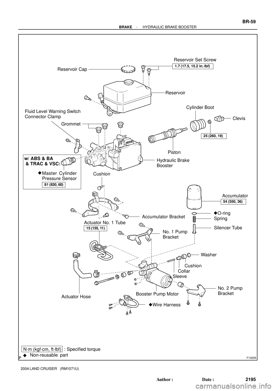
F13209
Reservoir Set Screw
Accumulator Bracket
No. 1 Pump
Bracket Actuator No. 1 TubeAccumulator
�O-ring
Silencer Tube Grommet
PistonCylinder Boot
Clevis Reservoir Cap
No. 2 Pump
Bracket SleeveCollar
Booster Pump MotorCushion
Actuator Hose
Non-reusable part N´m (kgf´cm, ft´lbf) : Specified torque
�
25 (260, 19)
Cushion Fluid Level Warning Switch
Connector Clamp
Hydraulic Brake
Booster
Spring
15 (155, 11)
�Wire Harness
Reservoir
1.7 (17.5, 15.2 in.´lbf)
54 (550, 36)
Washer
Master Cylinder
Pressure Sensor
81 (830, 60)
w/ ABS & BA
& TRAC & VSC:
�
- BRAKEHYDRAULIC BRAKE BOOSTER
BR-59
2195 Author�: Date�:
2004 LAND CRUISER (RM1071U)
Page 544 of 3115

DISASSEMBLY
1. PLACE HYDRAULIC BRAKE BOOSTER IN VI")
F04472
SST
SST
BR12D-05
F04473
SST
F13233
30 mm
Deeper
Socket BR-62
- BRAKEHYDRAULIC BRAKE BOOSTER
2198 Author�: Date�:
2004 LAND CRUISER (RM1071U)
DISASSEMBLY
1. PLACE HYDRAULIC BRAKE BOOSTER IN VISE
Using SST, set the hydraulic brake booster in vise.
SST 09630-00014 (09631-00142),
09950-60010 (09951-00180, 09951-00190)
2. REMOVE FLUID LEVEL WARNING SWITCH CONNEC-
TOR CLAMP
(a) Disconnect the connector.
(b) Remove the bolt and clamp.
3. REMOVE RESERVOIR AND GROMMETS
(a) Remove reservoir cap.
(b) Remove the 3 set screws and pull out the reservoir.
Torque: 1.7 N´m (17.5 kgf´cm, 15.2 in.´lbf)
(c) Remove the 3 grommets.
4. REMOVE CLEVIS AND CYLINDER BOOT
(a) Loosen the lock nut, then remove the clevis and lock nut.
Torque: 25 N´m (260 kgf´cm, 19 ft´lbf)
(b) Remove the cylinder boot.
5. REMOVE BRAKE ACTUATOR TUBE NO. 1
Using SST, remove the brake actuator tube No. 1.
SST 09023-00100
Torque: 15 N´m (155 kgf´cm, 11 ft´lbf)
6. REMOVE BOOSTER PUMP AND ASSEMBLY
(a) Remove the actuator hose.
(b) Remove the 4 screws and wire harness from the booster
and pump.
(c) Remove the 2 bolts, accumulator bracket.
(d) Remove the 2 bolts and booster pump motor assembly.
(e) Remove the bolt and No. 1 pump bracket.
(f) Remove the 2 washers, 2 cushions, 2 collars and sleeve.
(g) Remove the 2 bolts and No. 2 pump bracket.
(h) Remove the cushion from No. 2 pump bracket.
7. ABS & BA & TRAC & VSC only:
REMOVE MASTER CYLINDER PRESSURE SENSOR
Using 30 mm deeper socket wrench and remove the oil pres-
sure sensor.
Torque: 81 N´m (830 kgf´cm, 60 ft´lbf)
NOTICE:
If replacing the master cylinder pressuer sensor, since the
sensor is non-reusable, use a sensor of the supply part No
shown below.
PART NO: 89637-30050
Page 571 of 3115
BR0JX-05
F04970
ClipStopper Bolt
Bellcrank Bracket Parking Brake
Cable
PinTension Spring
Rear Shoe
Spring Return
Spring
Shoe StrutAdjuster
Cup
Shoe Hold-down Spring
Brake Disc Front Shoe Parking Brake
Shoe Lever
Parking Brake Cable No. 2� C-washer Rear Brake Caliper
Assembly
Tension
Spring
Cup
� C-washer
Shim
� C-washer
Pin
Bellcrank Boot
Tension Spring
Pin
Pin
Pin
N´m (kgf´cm, ft´lbf): Specified torque
Lithium soap base glycol grease
High temperature grease Non-reusable part
�Shoe Hold-down Spring
Cup
Clip
103 (1,050, 76)
Spring
13 (130, 9)
5.4 (55, 48 in.´lbf)
Bellcrank
- BRAKEPARKING BRAKE
BR-33
2169 Author�: Date�:
2004 LAND CRUISER (RM1071U)
PARKING BRAKE
COMPONENTS
Page 573 of 3115
F04976
F04977
F04978
F04979
- BRAKEPARKING BRAKE
BR-35
2171 Author�: Date�:
2004 LAND CRUISER (RM1071U)
8. REMOVE FRONT SHOE
(a) Slide out the front shoe.
(b) Disconnect the parking brake cable No. 2 from the park-
ing brake shoe lever.
(c) Remove the shoe hold-down spring, 2 cups and pin.
9. IF NECESSARY, REMOVE AND DISASSEMBLE
PARKING BRAKE BELLCRANK ASSEMBLY
(a) Using a screwdriver, remove the C-washer.
(b) Remove the pin and disconnect the parking brake cable
No. 2 from the bellcrank.
(c) Remove the clip and pin.
(d) Disconnect the parking brake cable and remove the clip.
(e) Remove the 2 tension springs.
(f) Remove the 2 bolts and parking brake bellcrank assem-
bly.
Torque: 13 N´m (130 kgf´cm, 9 ft´lbf)
(g) Turn the boot over from parking brake bellcrank bracket.
(h) Using a screwdriver, remove the C-washer and pin.
(i) Remove the parking brake bellcrank from the bellcrank
bracket.
(j) Remove the bellcrank boot from the bellcrank.

74 (750, 54)
Bleeder Plug
Brake Caliper
Inner Pad Clip
Boot Piston Seal
Piston
Set Ring
Axle Hub Disc
N´m (kgf´cm, ft´lbf): Specified torque
Lithium soap base glycol gre")