Page 2625 of 3115

TORQUE SPECIFICATION
Part tightenedN´mkgf´cmft´lbf
Crossmember x Frame5051037
Crossmember x Engine")
SS0ON-04
- SERVICE SPECIFICATIONSTRANSFER
SS-27
167 Author�: Date�:
2004 LAND CRUISER (RM1071U)
TORQUE SPECIFICATION
Part tightenedN´mkgf´cmft´lbf
Crossmember x Frame5051037
Crossmember x Engine rear mounting7475054
Transfer x Transmission6970051
Filler and drain plug3738027
Oil pump plate x Rear extension housing4.95043 in.´lbf
Oil pump cover x Rear extension housing4.95043 in.´lbf
Lever lock pin121209
Oil strainer x Rear case4.95043 in.´lbf
Oil receiver x Front case121209
Case cover x Rear case3738027
Rear extension housing x Rear case3738027
Front extension housing x Front case3738027
Transfer indicator switch (Center diff. lock)3738027
Transfer indicator switch (Low switch)3738027
Transfer indicator switch (Neutral switch)3738027
Screw plug x Front case1919014
Screw plug x Rear extension housing2930022
Motor actuator x Front case1818513
Differential front case x Differential rear caseSee page TR-31
Front case x Rear case3738027
Crossmember x Transfer case protector2829021
Speed sensor driven gear1111 58
Transfer shift lever rod assembly x Shift outer lever1414010
Transfer control shift lever retainer x Transmission1919014
Transfer x Front propeller shaft8082059
Front propeller shaft x Front differential8082059
Transfer x Rear propeller shaft1061,08078
Rear propeller shaft x Rear differential1061,08078
Rear extension housing x Retainer3940029
Page 2669 of 3115

SFI SYSTEM
PRECAUTION
1. BEFORE WORKING ON FUEL SYSTEM, DISCON-
NECT NEGATIVE (-) TERMINAL CABLE FROM BAT-
TERY
HINT:")
SF0XU-1 1
- SFISFI SYSTEM
SF-1
1700 Author�: Date�:
2004 LAND CRUISER (RM1071U)
SFI SYSTEM
PRECAUTION
1. BEFORE WORKING ON FUEL SYSTEM, DISCON-
NECT NEGATIVE (-) TERMINAL CABLE FROM BAT-
TERY
HINT:
Any diagnostic trouble code retained by the computer will be
erased when the negative (-) terminal cable is removed from
the battery.
Therefore, if necessary, read the diagnosis before removing the
negative (-) terminal cable from the battery.
2. DO NOT SMOKE OR WORK NEAR AN OPEN FLAME
WHEN WORKING ON THE FUEL SYSTEM
3. KEEP GASOLINE AWAY FROM RUBBER OR
LEATH-
ER PARTS
4. MAINTENANCE PRECAUTIONS
(a) Take following precautions to prevent the engine misfire.
(1) Check proper connection to battery terminals, etc.
(2) After repair work, check that the ignition coil termi-
nals and all other ignition system lines are recon-
nected securely.
(3) When cleaning the engine compartment, be espe-
cially careful to protect the electrical system from
water.
(b) Take following precautions to handle the oxygen sensor.
(1) Do not drop the oxygen sensor or hit against an ob-
ject.
(2) Do not allow the sensor to contact with water.
5. IF VEHICLE IS EQUIPPED WITH MOBILE RA-
DIO
SYSTEM (HAM, CB, ETC.)
If the vehicle is equipped with a mobile communication system,
refer to the precaution in the IN section.
6. AIR INDUCTION SYSTEM
(a) Separation of the engine oil dipstick, oil filler cap, PCV
hose, etc. may cause the engine to be out of tune.
(b) Disconnection, looseness or cracks in the parts of the air
induction system between the throttle body and cylinder
head will cause air suction, which makes the engine out
of tune.
7. ELECTRONIC CONTROL SYSTEM
(a) Disconnect the power by either turning the ignition switch
OFF or disconnecting the negative (-) terminal cable from
the battery before removing SFI wiring connectors, termi-
nals, etc.
HINT:
Always check the diagnostic trouble code before disconnecting
the negative (-) terminal cable from the battery.
(b) When installing the battery, be especially careful not to in-
correctly connect the positive (+) and negative (-) cables.
Page 2671 of 3115

(b)")
B04933
New Gasket
B04934
Fulcrum
Length
30 cm
SST
B04895
SST Fulcrum
Length
30 cm
B02714
CORRECT
WRONG
Delivery Pipe O-Ring
- SFISFI SYSTEM
SF-3
1702 Author�: Date�:
2004 LAND CRUISER (RM1071U)
(b) When connecting the union bolt (fuel pressure pulsation
damper) on the high pressure pipe union, follow the pro-
cedure below:
(1) Always use 2 new gaskets.
(2) Tighten the union bolt by hand.
(3) Using SST, tighten the union bolt to the specified
torque.
SST 09612-24014 (09617-24011)
Torque:
33 N´m (340 kgf´cm, 24 ft´lbf) for use with SST
39 N´m (400 kgf´cm, 29 ft´lbf)
HINT:
Use a torque wrench with a fulcrum length of 30 cm (11.81 in.).
(c) When connecting the flare nut on the high pressure pipe
union, follow the procedure below:
(1) Apply a light coat of engine oil to the flare nut, and
tighten the flare nut by hand.
(2) Using SST, tighten the flare nut to the specified
torque.
SST 09023-12700
NOTICE:
Do not rotate the fuel filter outlet when tightening the flare
nut.
Torque:
34 N´m (345 kgf´cm, 25 ft´lbf) for use with SST
38 N´m (380 kgf´cm, 28 ft´lbf)
HINT:
Use a torque wrench with a fulcrum length of 30 cm (11.81 in.).
(d) Take following precautions to remove and install the injec-
tors.
(1) Never reuse the O-ring.
(2) When placing a new O-ring on the injector, take
care not to damage it.
(3) Coat a new O-ring with spindle oil or gasoline be-
fore installing; never use engine, gear or brake oil.
Page 2673 of 3115

(4) Match the axis of the connector with that of the pipe,
and push")
B04897
Push
B04896
Pull
A07061
TOYOTA
Hand-Held
Tester
DLC3
- SFISFI SYSTEM
SF-5
1704 Author�: Date�:
2004 LAND CRUISER (RM1071U)
(4) Match the axis of the connector with that of the pipe,
and push in the connector until the connector
makes a ºclickº sound. In the joint part is too tight to
connect them, apply a little new engine oil on the tip
of the pipe.
(5) After finishing the connection, check if the pipe and
the connector are securely connected by pulling
them.
(6) Check if there is any fuel leakage.
(h) Take following precautions to handle the nylon tube.
(1) Pay attention not to turn the joint part of the nylon
tube and the quick connector by force when con-
necting them.
(2) Pay attention not to twist the nylon tube.
(3) Do not remove the EPDM protector on the outside
of the nylon tube.
(4) Do not connect them by bending the nylon tube.
(i) Check that there are no fuel leaks on the fuel system after
doing the maintenance.
(1) Connect the TOYOTA hand-held tester or OBD II
scan tool to the DLC3.
(2) Turn the ignition switch ON and press the TOYOTA
hand-held or OBD II scan tool tester main switch
ON.
NOTICE:
Do not start the engine.
(3) Select the ACTIVE TEST mode on the TOYOTA
hand-held tester or OBD II scan tool .
(4) Please refer to the TOYOTA hand-held tester or
OBD II scan tool operator's manual for further de-
tails.
(5) If you have no TOYOTA hand-held tester or OBD
II scan tool, connect the positive (+) and negative
(-) leads from the battery to the fuel pump connec-
tor (See page SF-7).
Page 2797 of 3115
B16458
EVAP Pipe
EVAP HoseRear Water
Bypass Joint
Injector Connector
VSV Connector
for EVAP
EVAP Hose
Starter Connector
V-Bank
Cover Bracket
Starter Intake Manifold AssemblyPS Air Hose Engine WireEVAP Hose
� Gasket
� Gasket
� Non-reusable part
39 (400, 29)
Engine Wire
Ignition Coil with
Igniter Connector
Water Bypass HoseEngine Wire
Engine Wire Protector
Fuel Return Hose
Engine Wire Protector
Engine Wire
V-Bank Cover Bracket
V-Bank
Cover Bracket
V-Bank
Cover Bracket
- STARTINGSTARTER
ST-3
1819 Author�: Date�:
2004 LAND CRUISER (RM1071U)
Page 2817 of 3115

or less
- STEERINGPOWER STEERING FLUID
SR-5
2214 Author�: Date�:
2004 LAND CRUISER (RM1071U)
INSPECTION
1. CH")
SR0LY-05
R00427
R11229
Normal
Abnormal
R11562Engine Idling
Engine Stopped 5 mm (0.2 in.)
or less
- STEERINGPOWER STEERING FLUID
SR-5
2214 Author�: Date�:
2004 LAND CRUISER (RM1071U)
INSPECTION
1. CHECK FLUID LEVEL
(a) Keep the vehicle level.
(b) With the engine stopped, check the fluid level in the oil
reservoir.
If necessary, add fluid.
Fluid: ATF DEXRON® II or III
HINT:
Check that the fluid level is within the HOT LEVEL range on the
reservoir.
If the fluid is cold, check that it is within the COLD LEVEL range.
(c) Start the engine and run it at idle.
(d) Turn the steering wheel from lock to lock several times to
boost fluid temperature.
Fluid temperature: 80°C (176°F)
(e) Check for foaming or emulsification.
If there is foaming or emulsification, bleed power steering sys-
tem (See page SR-4).
(f) With the engine idling, measure the fluid level in the oil
reservoir.
(g) Stop the engine.
(h) Wait a few minutes and remeasure the fluid level in the oil
reservoir.
Maximum fluid level rise: 5 mm (0.20 in.)
If a problem is found, bleed power steering system
(See page SR-4).
(i) Check the fluid level.
Page 2819 of 3115

Z15498
PS Gear
Closed
SSTPS Vane
Pump Oil
Reservoir
Z15499
PS Gear
SSTPS Vane
Pump Oil
Reservoir
Open
Z15500
PS Gear
SSTPS Vane
Pump Oil
Reservoir
Open Lock Position
- STEERINGPOWER STEERING FLUID
SR-7
2216 Author�: Date�:
2004 LAND CRUISER (RM1071U)
(g) With the engine idling, close the valve of the SST and ob-
serve the reading on the SST.
Minimum fluid pressure:
10,000 kPa (102 kgf/cm
2, 1,451 psi)
NOTICE:
�Do not keep the valve closed for more than 10 se-
conds.
�Do not let the fluid temperature become too high.
(h) With the engine idling, open the valve fully.
(i) Measure the fluid pressure at engine speeds of 1,000 rpm
and 3,000 rpm.
Difference fluid pressure:
490 kPa (5 kgf/cm
2, 71 psi) or less
NOTICE:
Do not turn the steering wheel.
(j) With the engine idling and valve fully opened, turn the
steering wheel to full lock.
Minimum fluid pressure:
10,000 kPa (102 kgf/cm
2, 1,451 psi)
NOTICE:
�Do not maintain lock position for more than 10 se-
conds.
�Do not let the fluid temperature become too high.
(k) Disconnect the SST.
SST 09640- 10010 (09641- 01010, 09641- 01030,
09641-01060)
(l) Connect the pressure feed tube (See page SR-47).
(m) Install the air cleaner assembly with air cleaner hose
(See page SR-47).
(n) Bleed the power steering system (See page SR-4).
Page 2820 of 3115
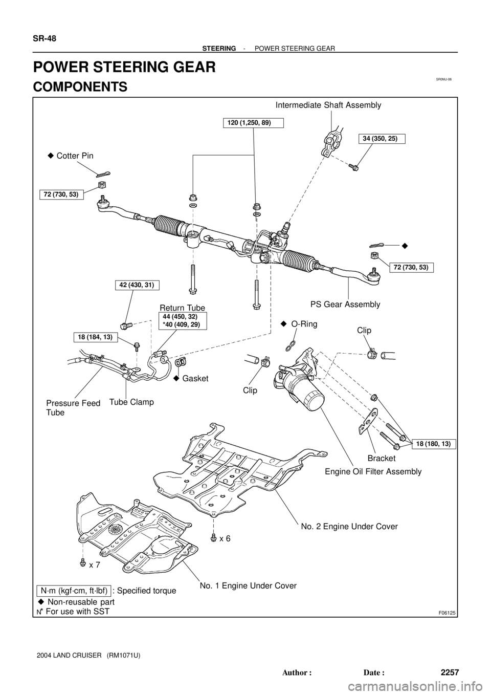
SR0MJ-06
F06125
� Cotter Pin
72 (730, 53)
Intermediate Shaft Assembly
34 (350, 25)
120 (1,250, 89)
18 (184, 13)
Tube ClampPressure Feed
Tube
44 (450, 32)
*40 (409, 29)
� Gasket�
72 (730, 53)
PS Gear Assembly
Return Tube
42 (430, 31)
Clip
Engine Oil Filter Assembly
No. 2 Engine Under Cover
x 6
x 7
No. 1 Engine Under CoverN´m (kgf´cm, ft´lbf) : Specified torque
� Non-reusable part
* For use with SST
Clip� O-Ring
18 (180, 13)
Bracket
SR-48
- STEERINGPOWER STEERING GEAR
2257 Author�: Date�:
2004 LAND CRUISER (RM1071U)
POWER STEERING GEAR
COMPONENTS