Page 24 of 3115

3. INSPECT IDLE-UP SPEED
(a) Warm up engine
(b) Inspect idle-up speed when following conditions are es")
- AIR CONDITIONINGAIR CONDITIONING SYSTEM
AC-9
2734 Author�: Date�:
2004 LAND CRUISER (RM1071U)
3. INSPECT IDLE-UP SPEED
(a) Warm up engine
(b) Inspect idle-up speed when following conditions are es-
tablished.
Test conditions:
�Fan speed selector at ºHIº position
�Temperature control dial at ºCOOLº position
�A/C switch ON
�Put gear shift in neutral
Magnetic clutch conditionIdle-up speed
Magnetic clutch not engaged700 ± 50 rpm
Magnetic clutch engaged780 ± 50 rpm
If idle speed is not as specified, check the idle control system.
4. INSPECT FOR LEAKAGE OF REFRIGERANT
(a) Stop engine.
(b) Secure good ventilation (The gas leak detector may not
react to volatile gases which are not refrigerant, such as
evaporated gasoline and exhaust gas)
(c) Repeat the test 2 or 3 times
(d) Make sure that there is some refrigerant remaining in the
refrigeration system.
When compressor is OFF: approx. 392 - 588 kPa (4 - 6
kgf´cm
2, 57 - 85 psi)
(e) Bring the gas leak detector close to the drain hose before
performing the test.
HINT:
�After the blower motor stops, leave the cooling for more
than 15 minutes.
�Expose the gas leak detector sensor under the drain
hose.
�When bring the gas leak detector close to the drain hose,
make sure that the gas leak detector does not react to the
volatile gases.
If gas leaks are detected, lift up the vehicle.
(f) If gas leaks are not detected on the drain hose, remove
the blower resistor from the cooling unit. Then insert the
gas leak detector sensor into the unit to perform the test.
(g) Disconnect the connector and leave the pressure switch
for approx. 20 minutes. Then bring the gas leak detector
close to the pressure switch to perform the test.
(h) Bring the gas leak detector close to the refrigerant lines.
Page 131 of 3115
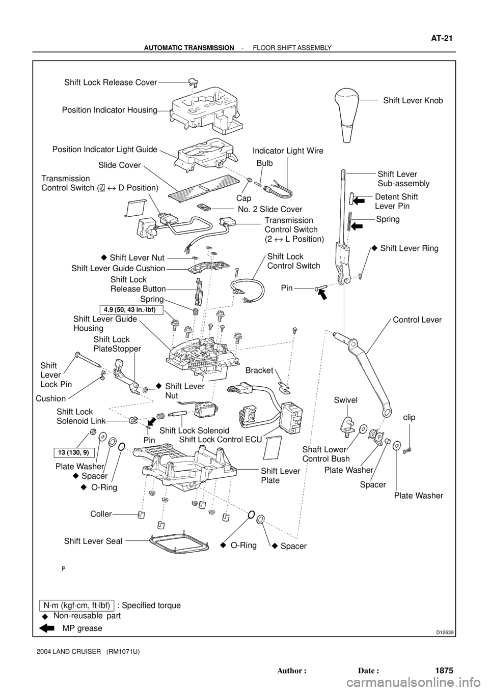
D12639
Position Indicator Housing
Position Indicator Light Guide
Slide Cover
No. 2 Slide Cover
� Shift Lever Nut
Shift Lever Guide Cushion
Shift Lever Guide
Housing
Bracket
Shift Lock Control ECU
Coller
13 (130, 9)
Plate Washer
� Spacer � O-Ring Shift Lever Seal� O-Ring � SpacerSwivel
Plate Washer
Spacer Shaft Lower
Control Bushclip
Plate Washer Control Lever
�
Pin
� Shift Lever Ring Spring Detent Shift
Lever PinShift Lever
Sub-assembly
Shift Lock Solenoid
Shift Lever
NutPinShift Lever Knob
Transmission
Control Switch (
e D Position)
Shift Lock
Control Switch CapBulb Indicator Light Wire
Shift Lock
Release Button
Spring
N´m (kgf´cm, ft´lbf) : Specified torque
�
MP grease Non-reusable partShift Lever
PlateTransmission
Control Switch
(2 e L Position)
Shift Lock
Solenoid Link
Shift
Lever
Lock Pin
4.9 (50, 43 in.´lbf)
Shift Lock Release Cover
Cushion
Shift Lock
PlateStopper
- AUTOMATIC TRANSMISSIONFLOOR SHIFT ASSEMBLY
AT-21
1875 Author�: Date�:
2004 LAND CRUISER (RM1071U)
Page 132 of 3115

DISASSEMBLY
1. REMOVE SHIFT LEVER KNOB
2. REMOVE POSITION INDICATOR HOUSING")
AT114-01
D12642
D12643
- AUTOMATIC TRANSMISSIONFLOOR SHIFT ASSEMBLY
AT-23
1877 Author�: Date�:
2004 LAND CRUISER (RM1071U)
DISASSEMBLY
1. REMOVE SHIFT LEVER KNOB
2. REMOVE POSITION INDICATOR HOUSING
(a) Using a small screwdriver, remove the shift lock release
cover from the position indicator housing.
(b) Remove the position indicator housing assembly.
3. REMOVE POSITION INDICATOR LIGHT GUIDE
(a) Disconnect the indicator lamp wire from the position indi-
cator light guide.
(b) Remove the position indicator light guide.
4. REMOVE SLIDE COVER AND NO. 2 SLIDE COVER
5. REMOVE SHIFT LEVER GUIDE HOUSING
(a) Disconnect the shift lock control ECU connector from the
shift lever plate.
(b) Disconnect the 2 transmission control switches and the
shift lock control switch from the shift lever guide housing.
(c) Remove the 4 bolts, nuts and the shift lever guide housing
assembly.
6. DISASSEMBLE SHIFT LEVER GUIDE HOUSING
(a) Using a screwdriver, pry up the 3 shift lever nuts.
(b) Using nippers, cut the 3 shift lever nuts off then.
HINT:
Remove the shift lever lock pin of the shift lever nut in the same
way.
(c) Remove the shift lever guide cushion.
(d) Remove the 3 screws, the shift lock control ECU and the
shift lock solenoid.
(e) Remove the shift lock control ECU bracket from the shift
lock control ECU.
(f) Disconnect the transmission control switch connector
from the shift lever guide housing.
(g) Remove the shift lock release button and the spring.
Page 133 of 3115

(h) Using a screwdriver, pry up the shift lever nut.
(i) Using nipper,")
D12644
D04836
D04855
D12645
AT-24
- AUTOMATIC TRANSMISSIONFLOOR SHIFT ASSEMBLY
1878 Author�: Date�:
2004 LAND CRUISER (RM1071U)
(h) Using a screwdriver, pry up the shift lever nut.
(i) Using nipper, cut the shift lever nut off then.
(j) Remove the shift lever lock pin, the shift lock plate stopper
and the cushion.
7. DISCONNECT SHIFT LOCK CONTROL ECU, SHIFT
LOCK SOLENOID, SHIFT LOCK CONTROL SWITCH
AND TRANSMISSION CONTROL SWITCH
(a) Disengage the secondary locking device of the shift lock
solenoid.
(b) Release the locking lug of the terminal 4 and 5, and pull
the terminals out from the rear.
HINT:
Remove the transmission control switch in the same way.
(c) Remove the shift lock solenoid.
(d) Using 2 mm dia. steel wire, remove the pin and the shift
lock solenoid link from the shift lock solenoid plunger.
(e) Disengage the secondary locking device of the shift lock
control ECU.
(f) Release the locking lag of the terminal 1, 2 and 8 pull the
terminals out from the rear.
(g) Remove the transmission control switch. (De 4)
(h) Release the locking lag of the terminal 5, 6 and 12 and pull
the terminals out from the rear.
(i) Remove the transmission control switch. (2eL)
(j) Release the locking lag of the terminal 7 and 14 and pull
the terminals out from the rear.
Page 137 of 3115

4. CONNECT SHIFT LOCK CONTROL ECU, SHIFT LOCK
SOLENOID, SHIFT LOCK CONTROL SWITCH, INDI-
CA")
D12642
- AUTOMATIC TRANSMISSIONFLOOR SHIFT ASSEMBLY
AT-27
1881 Author�: Date�:
2004 LAND CRUISER (RM1071U)
4. CONNECT SHIFT LOCK CONTROL ECU, SHIFT LOCK
SOLENOID, SHIFT LOCK CONTROL SWITCH, INDI-
CATOR LAMP WIRE AND 2 TRANSMISSION CON-
TROL SWITCH
5. REASSEMBLE SHIFT LEVER GUIDE HOUSING
(a) Apply MP grease to the shift lever lock pin.
(b) Install the shift lever lock pin, the shift lock plate stopper
and the cushion to the shift lever guide housing.
(c) Install a new shift lever nut to the shift lever lock pin by
knocking them lightly via the 10 mm seated nut.
HINT:
Install the shift lever guide cushion of the shift lever nut in the
same way.
(d) Apply MP grease to the shift lock release button.
(e) Install the spring and the shift lock release button.
(f) Connect the transmission control switch connector to the
shift lever guide housing.
(g) Install the shift lock control ECU bracket to the shift lock
control ECU.
(h) Install the shift lock control ECU and the shift lock sole-
noid with the 3 screws to the shift lever guide housing.
(i) Install the shift lever guide cushion with 3 new shift lever
nuts.
6. INSTALL SHIFT LEVER GUIDE HOUSING
(a) Install the shift lever guide housing assembly with the 4
bolts and nuts to the shift lever plate.
Torque: 4.9 N´m (50 kgf´cm, 43 in.´lbf)
(b) Install the 2 transmission control switches and the shift
lock control switch to the shift lever guide housing.
(c) Connect the shift lock control ECU connector to the shift
lever plate.
7. INSTALL SLIDE COVER AND NO. 2 SLIDE COVER
8. INSTALL POSITION INDICATOR LIGHT GUIDE
(a) Install the position indicator light guide.
(b) Connect the indicator lamp wire to the position indicator
light guide.
9. INSTALL POSITION INDICATOR HOUSING
(a) Install the position indicator housing.
(b) Install the shift lock release cover to the position indicator
housing.
10. INSTALL SHIFT LEVER KNOB
Page 141 of 3115

INSPECT")
AT07R-03
D12730
Connector A
Connector BIG
ACC
KLS
+
E STPP
P2SLS-
P1
SLS
+
11
3 4
9
10
D12731
AT-14
- AUTOMATIC TRANSMISSIONSHIFT LOCK SYSTEM
1868 Author�: Date�:
2004 LAND CRUISER (RM1071U)
INSPECTION
1. INSPECT SHIFT LOCK CONTROL ECU
Using a voltmeter, measure the voltage at each terminal.
HINT:
Do not disconnect the ECU connector.
TerminalMeasuring ConditionVoltage (V)
Connector A
3 - 10 (ACC - E)Ignition switch ACC10 - 14
4 - 10 (IG - E)Ignition switch ON10 - 14
10 - 11 (E - STP)Depress brake pedal10 - 14
9 - 10 (KLS+ - E)
(1) Ignition switch ACC and P position
(2) Ignition switch ACC and except P position
(3) (After approx. 1 second)0
7.5 - 10.5
6 - 9
Connector B
1 - 2 (SLS+ - SLS-)
(1) Ignition switch ON and P position
(2) Depress brake pedal
(3) Shift except P position under conditions above0
8.5 - 13.5
0
3 - 4 (P1 - P)(1) Ignition switch ON, P position and depress brake pedal
(2) Shift except P position under condition above0
9 - 13.5
4 - 5 (P - P2)(1) Ignition switch ACC and P position
(2) Shift except P position under condition above9 - 13.5
0
2. INSPECT SHIFT LOCK SOLENOID
(a) Disconnect the solenoid connector.
(b) Using an ohmmeter, measure the resistance between ter-
minal 1 and 2.
Standard resistance: 21 - 27 W
If the resistance value is not as specified, replace the solenoid.
(c) Apply the battery positive voltage between terminals.
Check that the operation noise can be heard from the so-
lenoid.
If the solenoid does not operate, replace the solenoid.
3. INSPECT SHIFT LOCK CONTROL SWITCH
Inspect that continuity exists between each terminal.
Shift positionTester connectionSpecified value
P position (Release
button is not pushed)3 - 4 (P - P1)Continuity
P position (Release
button is pushed)3 - 4 (P - P1)
4 - 5 (P - P2)Continuity
R, N, D, 2, L position4 - 5 (P - P2)Continuity
If continuity is not as specified, replace the switch.
Page 143 of 3115
AT07Q-03
D12729
Key Interlock Solenoid
Stop Light Switch
Shift Lock Control ECU
Shift Lock Solenoid Bracket
- AUTOMATIC TRANSMISSIONSHIFT LOCK SYSTEM
AT-13
1867 Author�: Date�:
2004 LAND CRUISER (RM1071U)
SHIFT LOCK SYSTEM
LOCATION
Page 164 of 3115
BE0GD-23
I25523
Cowl SIde J/B RH
� RADIO Fuse
TweeterRadio Assembly
Ignition Switch
Engine Room R/B
� AMP Fuse
Woofer SpeakersSpeakers
Power Amplifier Steering Pad Switch
RSA
Antenna Assembly
� Motor Antenna
Cowl Side J/B LH
� ECU IG1 Fuse
� IG Fuse
BE-170
- BODY ELECTRICALAUDIO SYSTEM
2543 Author�: Date�:
2004 LAND CRUISER (RM1071U)
LOCATION