Page 1895 of 3115

A04330
A04329
A04331
EM-26
- ENGINE MECHANICALTIMING BELT
1599 Author�: Date�:
2004 LAND CRUISER (RM1071U)
20. INSTALL NO.2 TIMING BELT COVER
Install the No.2 timing belt cover with the 2 bolts.
Torque: 16 N´m (160 kgf´cm, 12 ft´lbf)
21. INSTALL RH NO.3 TIMING BELT COVER
(a) Fit the RH No.3 timing belt cover, matching it with the fan
bracket.
(b) Install the RH No.3 timing belt cover with the 3 bolts and
nut.
Torque: 7.5 N´m (80 kgf´cm, 66 in.´lbf)
22. INSTALL LH NO.3 TIMING BELT COVER
(a) Install the oil cooler pipe and the bolt.
(b) Run the camshaft position sensor wire through the LH
No.3 timing belt cover hole.
(c) Fit the LH No.3 timing belt cover, matching it with the fan
bracket.
(d) Install the LH No.3 timing belt cover with the 4 bolts and
the nut.
Torque: 7.5 N´m (80 kgf´cm, 66 in.´lbf)
(e) Install the wire grommet to the LH No.3 timing belt cover.
(f) Install the sensor connector to the connector bracket.
(g) Connect the sensor connector.
(h) Install the sensor wire to the wire clamp on the LH No.3
timing belt cover.
(i) Install the engine wire to the 2 wire clamps on the LH No.3
timing belt cover.
23. INSTALL DRIVE BELT IDLER PULLEY
Install the idler pulley and the cover plate with the bolt.
Torque: 37 N´m (380 kgf´cm, 27 ft´lbf)
24. INSTALL RADIATOR ASSEMBLY
(See page CO-19)
Page 1896 of 3115
A02247
- ENGINE MECHANICALTIMING BELT
EM-27
1600 Author�: Date�:
2004 LAND CRUISER (RM1071U)
25. INSTALL FAN PULLEY, FAN, FLUID COUPLING
AND DRIVE BELT
(a) Temporarily install the fan pulley, the fan, fluid coupling
assembly with the 4 nuts.
(b) Install the generator drive belt.
(See page CH-16)
(c) Tighten the 4 nuts holding the fluid coupling to the fan
bracket.
Torque: 21 N´m (215 kgf´cm, 16 ft´lbf)
26. INSTALL AIR CLEANER AND INTAKE AIR
CONNECTOR ASSEMBLY
27. INSTALL V-BANK COVER
28. FILL WITH ENGINE COOLANT
29. START ENGINE AND CHECK FOR LEAKS
30. RECHECK ENGINE COOLANT LEVEL
31. INSTALL BATTERY CLAMP COVER
32. INSTALL ENGINE UNDER COVER
33. INSTALL OIL PAN PROTECTOR
Page 1897 of 3115
EM1VA-01
A02247
A04329
- ENGINE MECHANICALTIMING BELT
EM-15
1588 Author�: Date�:
2004 LAND CRUISER (RM1071U)
REMOVAL
1. REMOVE OIL PAN PROTECTOR
2. REMOVE ENGINE UNDER COVER
3. DRAIN ENGINE COOLANT
4. REMOVE BATTERY CLAMP COVER
5. REMOVE V-BANK COVER
(a) Remove the fuel return hose from the V-bank cover.
(b) Remove the 2 bolt, 2 cap nuts and V-bank cover.
6. REMOVE AIR CLEANER AND INTAKE AIR CONNEC-
TOR ASSEMBLY
7. REMOVE DRIVE BELT, FAN, FLUID COUPLING AND
FAN PULLEY
(a) Loosen the 4 nuts holding the fluid coupling to the fan
bracket.
(b) Remove the generator drive belt.
(See page CH-7)
(c) Remove the 4 nuts, the fan, the fluid coupling assembly
and the fan pulley.
8. REMOVE RADIATOR ASSEMBLY
(See page CO-17)
9. REMOVE DRIVE BELT IDLER PULLEY
Remove the pulley bolt, the cover plate and the idler pulley.
10. REMOVE RH NO.3 TIMING BELT COVER
Remove the 3 bolts, the nut and the RH No.3 timing belt cover.
Page 1898 of 3115

A04331
A04330
A04455
A04332
EM-16
- ENGINE MECHANICALTIMING BELT
1589 Author�: Date�:
2004 LAND CRUISER (RM1071U)
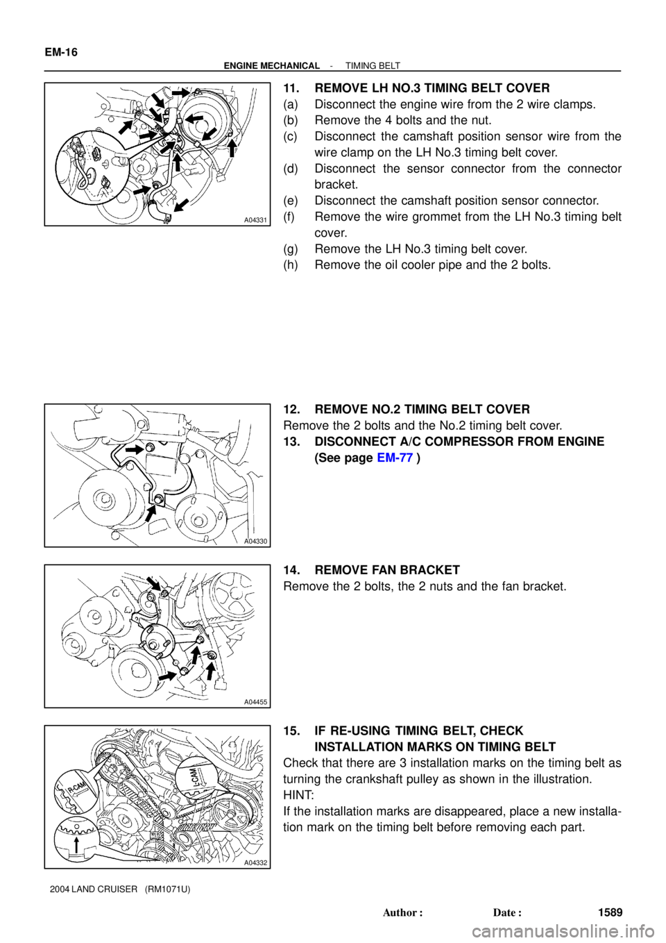
11. REMOVE LH NO.3 TIMING BELT COVER
(a) Disconnect the engine wire from the 2 wire clamps.
(b) Remove the 4 bolts and the nut.
(c) Disconnect the camshaft position sensor wire from the
wire clamp on the LH No.3 timing belt cover.
(d) Disconnect the sensor connector from the connector
bracket.
(e) Disconnect the camshaft position sensor connector.
(f) Remove the wire grommet from the LH No.3 timing belt
cover.
(g) Remove the LH No.3 timing belt cover.
(h) Remove the oil cooler pipe and the 2 bolts.
12. REMOVE NO.2 TIMING BELT COVER
Remove the 2 bolts and the No.2 timing belt cover.
13. DISCONNECT A/C COMPRESSOR FROM ENGINE
(See page EM-77)
14. REMOVE FAN BRACKET
Remove the 2 bolts, the 2 nuts and the fan bracket.
15. IF RE-USING TIMING BELT, CHECK
INSTALLATION MARKS ON TIMING BELT
Check that there are 3 installation marks on the timing belt as
turning the crankshaft pulley as shown in the illustration.
HINT:
If the installation marks are disappeared, place a new installa-
tion mark on the timing belt before removing each part.
Page 1902 of 3115

EM0KS-08
A04324
A04325
EM-4
- ENGINE MECHANICALVALVE CLEARANCE
1577 Author�: Date�:
2004 LAND CRUISER (RM1071U)
VALVE CLEARANCE
INSPECTION
HINT:
Inspect and adjust the valve clearance when the engine is cold.
1. DRAIN ENGINE COOLANT
2. REMOVE BATTERY CLAMP COVER
3. REMOVE V-BANK COVER
4. REMOVE AIR CLEANER AND INTAKE AIR CONNEC-
TOR ASSEMBLY
5. REMOVE NO.3 TIMING BELT COVERS
(See page EM-15)
6. REMOVE IGNITION COILS (See page IG-6)
7. REMOVE RH CYLINDER HEAD COVER
Remove the 9 bolts, the 9 seal washers and the cylinder head
cover.
8. REMOVE LH CYLINDER HEAD COVER
(a) Remove the oil dipstick for the transmission.
(b) Disconnect the PCV hose.
(c) Disconnect the engine wire clamp from the wire bracket
on the cylinder head cover.
(d) Remove the 9 bolts, the 9 seal washers and the cylinder
head cover.
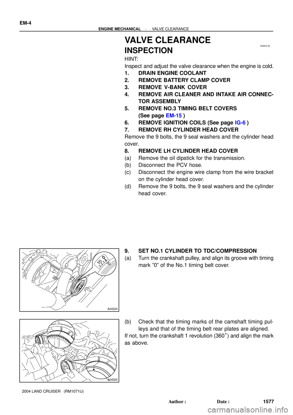
9. SET NO.1 CYLINDER TO TDC/COMPRESSION
(a) Turn the crankshaft pulley, and align its groove with timing
mark º0º of the No.1 timing belt cover.
(b) Check that the timing marks of the camshaft timing pul-
leys and that of the timing belt rear plates are aligned.
If not, turn the crankshaft 1 revolution (360°) and align the mark
as above.
Page 1904 of 3115
EM-6
- ENGINE MECHANICALVALVE CLEARANCE
1579 Author�: Date�:
2004 LAND CRUISER (RM1071U)
Intake:
N = T + (A - 0.20 mm (0.008 in.))
Exhaust:
N = T + (A - 0.30 mm (0.012 in.))
�Select a new shim with the closest thickness as
close as possible to the calculated value.
HINT:
Shims are available in 41 increments of 0.020 mm (0.0008 in.),
from 2.00 mm (0.0787 in.) to 2.80 mm (0.1102 in.).
(e) Place a new adjusting shim on the valve.
(f) Place the valve lifter.
(g) Reinstall the camshafts (See page EM-57).
(h) Reinstall the timing belt (See page EM-22).
(i) Recheck the valve clearance.
12. REINSTALL CYLINDER HEAD COVERS
13. REINSTALL IGNITION COILS
14. REINSTALL NO.3 TIMING BELT COVERS (See page
EM-22)
15. REINSTALL AIR CLEANER AND INTAKE AIR CON-
NECTOR ASSEMBLY
16. REFILL WITH ENGINE COOLANT
17. START ENGINE AND CHECK FOR LEAKS
18. RECHECK ENGINE COOLANT LEVEL
19. REINSTALL V-BANK COVER
20. REINSTALL BATTERY CLAMP COVER
Page 1950 of 3115

2004 LAND CRUISER (EWD548U)
69 G
Position of Parts in Engine Compartment
H 1 Headlight LH (High)
H 2 Headlight LH (Low)
H 3 Headlight RH (High)
H 4 Headlight RH (Low)
H 5 Heated Oxygen Sensor (Bank 1 Sensor 1)
H 6 Heated Oxygen Sensor (Bank 1 Sensor 2)
H 7 Heated Oxygen Sensor (Bank 2 Sensor 1)
H 8 Heated Oxygen Sensor (Bank 2 Sensor 2)
H 9 Horn LH
H 10 Horn RH
I 1 Ignition Coil and Igniter No.1
I 2 Ignition Coil and Igniter No.2
I 3 Ignition Coil and Igniter No.3
I 4 Ignition Coil and Igniter No.4
I 5 Ignition Coil and Igniter No.5
I 6 Ignition Coil and Igniter No.6
I 7 Ignition Coil and Igniter No.7
I 8 Ignition Coil and Igniter No.8
I 9 Injector No.1
I 10 Injector No.2
I 11 Injector No.3
I 12 Injector No.4
I 13 Injector No.5
I 14 Injector No.6
I 15 Injector No.7
I 16 Injector No.8K 1 Knock Sensor 1
K 2 Knock Sensor 2
M 1 Mass Air Flow Meter
M 4 Master Cylinder Pressure Sensor
N 1 Noise Filter (Ignition)
O 2 Oil Pressure Sender
P 1 Park/Neutral Position SW
P 2 Parking Light LH
P 3 Parking Light RH
S 1 Starter
S 2 Starter
T 1 Theft Deterrent Horn
T 16 Throttle Control Motor and Sensor
T 17 Turbine Speed Sensor
V 2 Vehicle Speed Sensor (Combination Meter)
V 3 Vehicle Speed Sensor
(Electronically Controlled Transmission)
V 4 VSV (EVAP)
V 9 VSV (Canister Closed Valve)
W 1 Washer Motor
Page 1963 of 3115
2004 LAND CRUISER (EWD548U)
380I GROUND POINT
5
Engine
Control
Module E 9
ECE10 5
IH2
IX18E10 E10 Ignition Coil and
Igniter No. 1
Ignition Coil and
Igniter No. 2
Ignition Coil and
Igniter No. 3
Ignition Coil and
Igniter No. 4
Data Link
Connector 3
Combination
SWIgnition Coil and
Igniter No. 5
Ignition Coil and
Igniter No. 6
Ignition Coil and
Igniter No. 7
Ignition Coil and
Igniter No. 8
Center Diff. Lock
Control Motor
Detection SW
(
Transfer Neutral
Position)
EB1
Detection SW
(
Center Diff. Lock)
(
E01)
(
E02)
(
E03)
(
ME01)
Combination
MeterED
IX2 5
E10W- B
W- B
W- B
W- B
W- B
W- B
W- B BR SB BR
BR
SB
W- BBR SB
BR
W- B
W- B
W- B
W- B
W- BW- BW- B
W- B
W- B
W- B
W- B
BR
E10
E10Vehicle Speed
Sensor
(
Combination Meter) BR
BR BR
BR
(
SG)
A/C Magnetic Clutch
A/C Lock SensorEB1 9
W- BIX1 9 3Q53
3E10
W- B
W- B
Noise Filter
(
Ignition) (
ECC)
BR
(
E1)
E10 BR BR
BR
BR