Page 1847 of 3115
A05504Front
A05505
Push
A04469
A
B
C
C
E
E
D
D
E
E
A04469
10
1
256789
1112 13
141516
1718
19
2022
3
4
21
EM-64
- ENGINE MECHANICALCYLINDER HEAD
1637 Author�: Date�:
2004 LAND CRUISER (RM1071U)
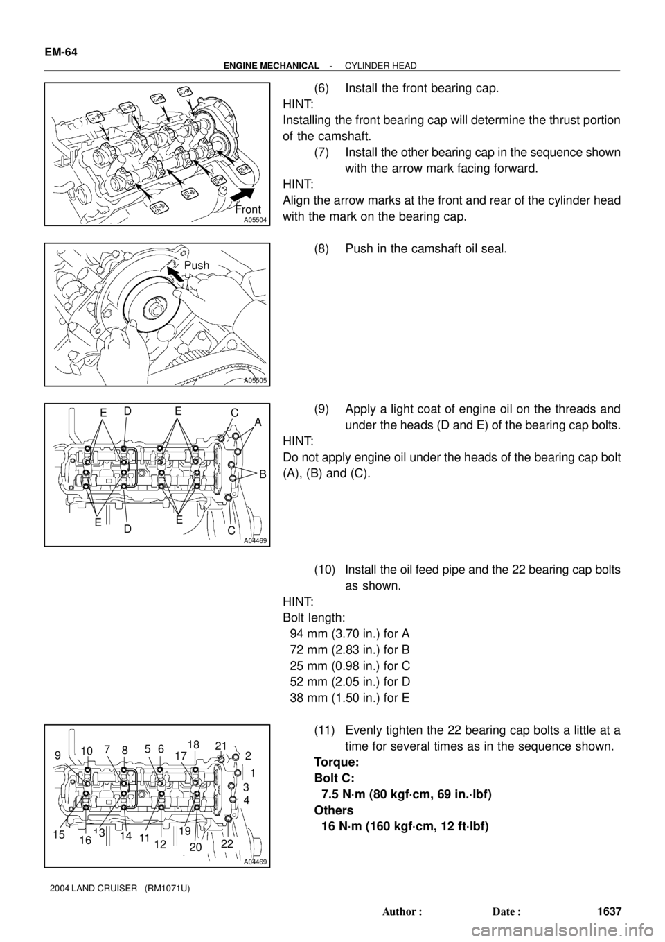
(6) Install the front bearing cap.
HINT:
Installing the front bearing cap will determine the thrust portion
of the camshaft.
(7) Install the other bearing cap in the sequence shown
with the arrow mark facing forward.
HINT:
Align the arrow marks at the front and rear of the cylinder head
with the mark on the bearing cap.
(8) Push in the camshaft oil seal.
(9) Apply a light coat of engine oil on the threads and
under the heads (D and E) of the bearing cap bolts.
HINT:
Do not apply engine oil under the heads of the bearing cap bolt
(A), (B) and (C).
(10) Install the oil feed pipe and the 22 bearing cap bolts
as shown.
HINT:
Bolt length:
94 mm (3.70 in.) for A
72 mm (2.83 in.) for B
25 mm (0.98 in.) for C
52 mm (2.05 in.) for D
38 mm (1.50 in.) for E
(11) Evenly tighten the 22 bearing cap bolts a little at a
time for several times as in the sequence shown.
Torque:
Bolt C:
7.5 N´m (80 kgf´cm, 69 in.´lbf)
Others
16 N´m (160 kgf´cm, 12 ft´lbf)
Page 1849 of 3115
A05507
Push
A04470
E D E
C
A
E D
E C B
A04470
10
1
2
56789
111213
141516
17 18
19
2022
3
4
21
A02856
Service
Bolt
EM-66
- ENGINE MECHANICALCYLINDER HEAD
1639 Author�: Date�:
2004 LAND CRUISER (RM1071U)
(8) Push in the camshaft oil seal.
(9) Apply a light coat of engine oil on the threads and
under the heads (D and E) of the bearing cap bolts.
HINT:
Do not apply engine oil under the heads of the bearing cap bolt
(A), (B) and (C).
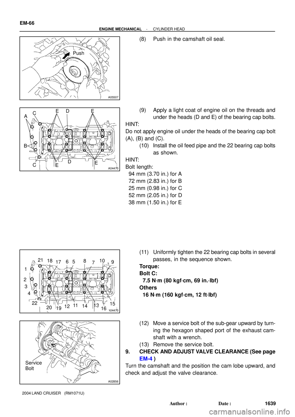
(10) Install the oil feed pipe and the 22 bearing cap bolts
as shown.
HINT:
Bolt length:
94 mm (3.70 in.) for A
72 mm (2.83 in.) for B
25 mm (0.98 in.) for C
52 mm (2.05 in.) for D
38 mm (1.50 in.) for E
(11) Uniformly tighten the 22 bearing cap bolts in several
passes, in the sequence shown.
Torque:
Bolt C:
7.5 N´m (80 kgf´cm, 69 in.´lbf)
Others
16 N´m (160 kgf´cm, 12 ft´lbf)
(12) Move a service bolt of the sub-gear upward by turn-
ing the hexagon shaped port of the exhaust cam-
shaft with a wrench.
(13) Remove the service bolt.
9. CHECK AND ADJUST VALVE CLEARANCE (See page
EM-4)
Turn the camshaft and the position the cam lobe upward, and
check and adjust the valve clearance.
Page 1850 of 3115
EM7143
Seal Packing
A07250
RH Cylinder Head
LH Cylinder Head
A05509
RH Cylinder Head
LH Cylinder HeadApply Seal Packing
Apply Seal Packing
- ENGINE MECHANICALCYLINDER HEAD
EM-67
1640 Author�: Date�:
2004 LAND CRUISER (RM1071U)
10. INSTALL SEMI-CIRCULAR PLUGS
(a) Remove any old packing (FIPG) material.
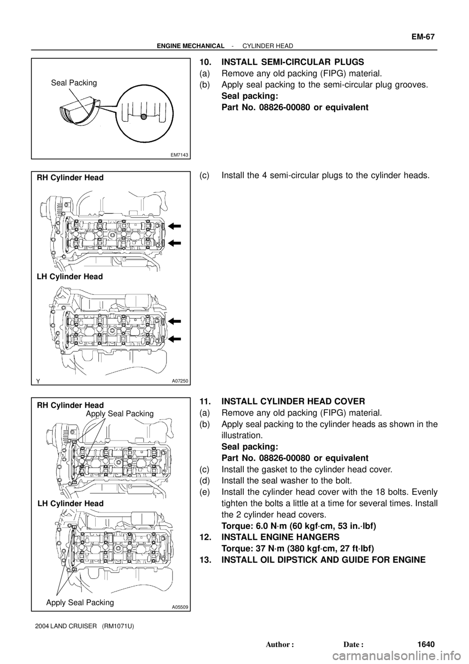
(b) Apply seal packing to the semi-circular plug grooves.
Seal packing:
Part No. 08826-00080 or equivalent
(c) Install the 4 semi-circular plugs to the cylinder heads.
11. INSTALL CYLINDER HEAD COVER
(a) Remove any old packing (FIPG) material.
(b) Apply seal packing to the cylinder heads as shown in the
illustration.
Seal packing:
Part No. 08826-00080 or equivalent
(c) Install the gasket to the cylinder head cover.
(d) Install the seal washer to the bolt.
(e) Install the cylinder head cover with the 18 bolts. Evenly
tighten the bolts a little at a time for several times. Install
the 2 cylinder head covers.
Torque: 6.0 N´m (60 kgf´cm, 53 in.´lbf)
12. INSTALL ENGINE HANGERS
Torque: 37 N´m (380 kgf´cm, 27 ft´lbf)
13. INSTALL OIL DIPSTICK AND GUIDE FOR ENGINE
Page 1853 of 3115
B15320B16469No. 1 Water Bypass Hose
EM-70
- ENGINE MECHANICALCYLINDER HEAD
1643 Author�: Date�:
2004 LAND CRUISER (RM1071U)
(r) Connect the PS air hose to intake manifold.
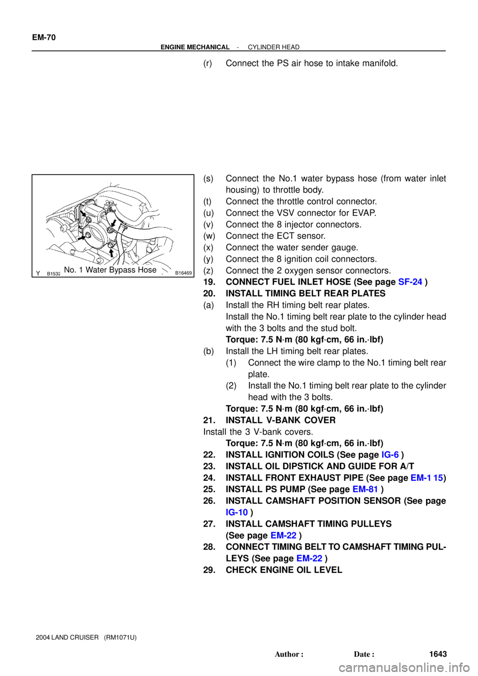
(s) Connect the No.1 water bypass hose (from water inlet
housing) to throttle body.
(t) Connect the throttle control connector.
(u) Connect the VSV connector for EVAP.
(v) Connect the 8 injector connectors.
(w) Connect the ECT sensor.
(x) Connect the water sender gauge.
(y) Connect the 8 ignition coil connectors.
(z) Connect the 2 oxygen sensor connectors.
19. CONNECT FUEL INLET HOSE (See page SF-24)
20. INSTALL TIMING BELT REAR PLATES
(a) Install the RH timing belt rear plates.
Install the No.1 timing belt rear plate to the cylinder head
with the 3 bolts and the stud bolt.
Torque: 7.5 N´m (80 kgf´cm, 66 in.´lbf)
(b) Install the LH timing belt rear plates.
(1) Connect the wire clamp to the No.1 timing belt rear
plate.
(2) Install the No.1 timing belt rear plate to the cylinder
head with the 3 bolts.
Torque: 7.5 N´m (80 kgf´cm, 66 in.´lbf)
21. INSTALL V-BANK COVER
Install the 3 V-bank covers.
Torque: 7.5 N´m (80 kgf´cm, 66 in.´lbf)
22. INSTALL IGNITION COILS (See page IG-6)
23. INSTALL OIL DIPSTICK AND GUIDE FOR A/T
24. INSTALL FRONT EXHAUST PIPE (See page EM-1 15)
25. INSTALL PS PUMP (See page EM-81)
26. INSTALL CAMSHAFT POSITION SENSOR (See page
IG-10)
27. INSTALL CAMSHAFT TIMING PULLEYS
(See page EM-22)
28. CONNECT TIMING BELT TO CAMSHAFT TIMING PUL-
LEYS (See page EM-22)
29. CHECK ENGINE OIL LEVEL
Page 1854 of 3115
EM0L4-08
P08885
Adhesive
15 mm (0.59 in.)
A03212
Protrusion
A05710
SST
A05711
(1)(2)(3)(4)
- ENGINE MECHANICALCYLINDER HEAD
EM-57
1630 Author�: Date�:
2004 LAND CRUISER (RM1071U)
REASSEMBLY
HINT:
�Thoroughly clean all parts to be assembled.
�Before installing the parts, apply new engine oil to all slid-
ing and rotating surfaces.
�Replace all gaskets and oil seals with new ones.
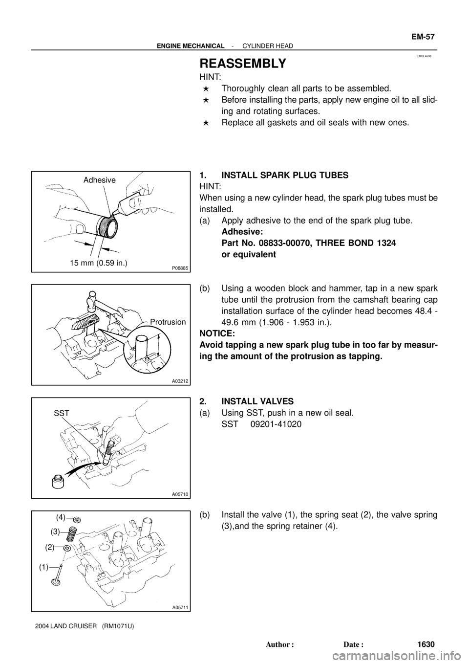
1. INSTALL SPARK PLUG TUBES
HINT:
When using a new cylinder head, the spark plug tubes must be
installed.
(a) Apply adhesive to the end of the spark plug tube.
Adhesive:
Part No. 08833-00070, THREE BOND 1324
or equivalent
(b) Using a wooden block and hammer, tap in a new spark
tube until the protrusion from the camshaft bearing cap
installation surface of the cylinder head becomes 48.4 -
49.6 mm (1.906 - 1.953 in.).
NOTICE:
Avoid tapping a new spark plug tube in too far by measur-
ing the amount of the protrusion as tapping.
2. INSTALL VALVES
(a) Using SST, push in a new oil seal.
SST 09201-41020
(b) Install the valve (1), the spring seat (2), the valve spring
(3),and the spring retainer (4).
Page 1856 of 3115
EM1V8-01
A02844
- ENGINE MECHANICALCYLINDER HEAD
EM-35
1608 Author�: Date�:
2004 LAND CRUISER (RM1071U)
REMOVAL
1. DRAIN ENGINE COOLANT
2. REMOVE V-BANK COVER
Remove the V-bank covers.
3. DISCONNECT TIMING BELT FROM CAMSHAFT TIM-
ING PULLEYS (See page EM-15)
4. REMOVE CAMSHAFT TIMING PULLEYS (See page
EM-15)
5. REMOVE CAMSHAFT POSITION SENSOR (See page
IG-9)
6. DISCONNECT PS PUMP FROM ENGINE
(See page EM-77)
7. REMOVE FRONT EXHAUST PIPE (See page EM-1 15)
8. REMOVE OIL DIPSTICK AND GUIDE FOR A/T
9. REMOVE IGNITION COILS (See page IG-6)
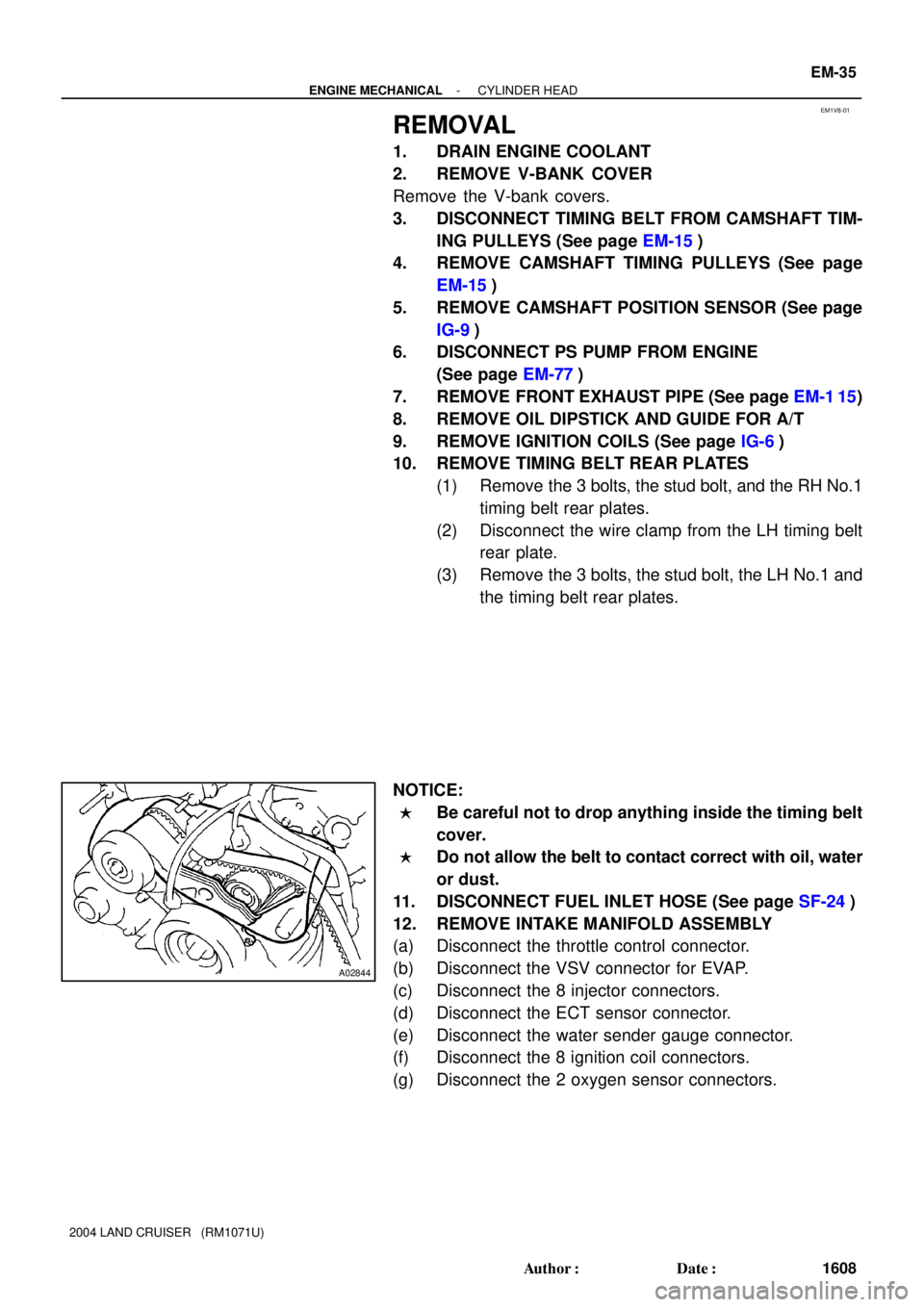
10. REMOVE TIMING BELT REAR PLATES
(1) Remove the 3 bolts, the stud bolt, and the RH No.1
timing belt rear plates.
(2) Disconnect the wire clamp from the LH timing belt
rear plate.
(3) Remove the 3 bolts, the stud bolt, the LH No.1 and
the timing belt rear plates.
NOTICE:
�Be careful not to drop anything inside the timing belt
cover.
�Do not allow the belt to contact correct with oil, water
or dust.
11. DISCONNECT FUEL INLET HOSE (See page SF-24)
12. REMOVE INTAKE MANIFOLD ASSEMBLY
(a) Disconnect the throttle control connector.
(b) Disconnect the VSV connector for EVAP.
(c) Disconnect the 8 injector connectors.
(d) Disconnect the ECT sensor connector.
(e) Disconnect the water sender gauge connector.
(f) Disconnect the 8 ignition coil connectors.
(g) Disconnect the 2 oxygen sensor connectors.
Page 1859 of 3115
A05516
A05517
A05564
EM-38
- ENGINE MECHANICALCYLINDER HEAD
1611 Author�: Date�:
2004 LAND CRUISER (RM1071U)
14. REMOVE WATER INLET AND INLET HOUSING AS-
SEMBLY (See page CO-6)
15. REMOVE FRONT WATER BYPASS JOINT
Remove the 4 nuts, the water bypass joint and the 2 gaskets.
16. REMOVE REAR WATER BYPASS JOINT
Remove the 4 nuts, the water bypass joint and the 2 gaskets.
17. REMOVE ENGINE HANGERS
18. REMOVE OIL DIPSTICK AND GUIDE FOR A/T
19. REMOVE CYLINDER HEAD COVERS
Remove the 18 bolts, the 18 seal washers, the cylinder head
cover and gasket. Remove the 2 cylinder head covers.
20. IF NECESSARY, REMOVE SEMI-CIRCULAR PLUGS
AND CAMSHAFT HOUSING PLUGS
21. REMOVE CAMSHAFTS
NOTICE:
Since the thrust clearance of the camshaft is small, the
camshaft must be kept level while it is being removed.
Otherwise, excessive pressure is put on the cylinder head
journal thrust, causing a burr on the journal and damage on
the camshaft. To avoid this, follow the steps below.
Page 1860 of 3115
A04456
No. 2 Idler
Pulley Bolt
Crankshaft
Pulley BoltTiming
Mark
A04467Service Bolt
A04468
A04469
8101241
14161862
19
2021
22
1315175
79113
- ENGINE MECHANICALCYLINDER HEAD
EM-39
1612 Author�: Date�:
2004 LAND CRUISER (RM1071U)
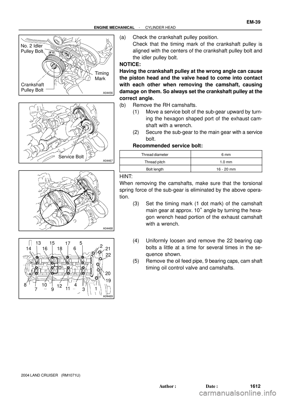
(a) Check the crankshaft pulley position.
Check that the timing mark of the crankshaft pulley is
aligned with the centers of the crankshaft pulley bolt and
the idler pulley bolt.
NOTICE:
Having the crankshaft pulley at the wrong angle can cause
the piston head and the valve head to come into contact
with each other when removing the camshaft, causing
damage on them. So always set the crankshaft pulley at the
correct angle.
(b) Remove the RH camshafts.
(1) Move a service bolt of the sub-gear upward by turn-
ing the hexagon shaped port of the exhaust cam-
shaft with a wrench.
(2) Secure the sub-gear to the main gear with a service
bolt.
Recommended service bolt:
Thread diameter6 mm
Thread pitch1.0 mm
Bolt length16 - 20 mm
HINT:
When removing the camshafts, make sure that the torsional
spring force of the sub-gear is eliminated by the above opera-
tion.
(3) Set the timing mark (1 dot mark) of the camshaft
main gear at approx. 10° angle by turning the hexa-
gon wrench head portion of the exhaust camshaft
with a wrench.
(4) Uniformly loosen and remove the 22 bearing cap
bolts a little at a time for several times in the se-
quence shown.
(5) Remove the oil feed pipe, 9 bearing caps, cam shaft
timing oil control valve and camshafts.