Page 1861 of 3115

A02856Service Bolt
A02857
Align
A04470
4
6
108
1
16
12
18 2
19 20 2221
15
3
5
97
14
1713
11
A02859
A02850
SST
Service Bolt
Turn EM-40
- ENGINE MECHANICALCYLINDER HEAD
1613 Author�: Date�:
2004 LAND CRUISER (RM1071U)
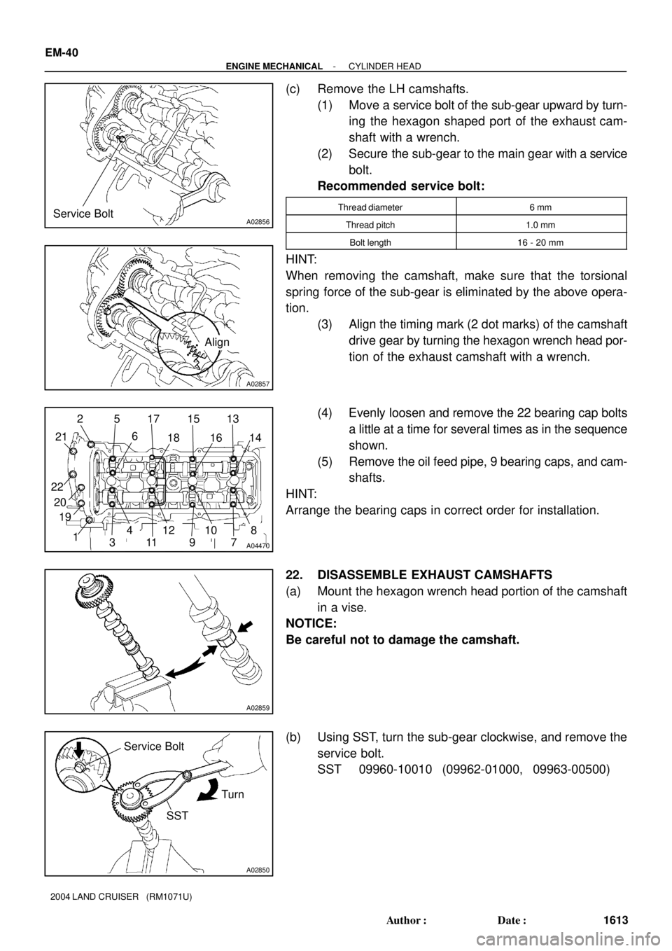
(c) Remove the LH camshafts.
(1) Move a service bolt of the sub-gear upward by turn-
ing the hexagon shaped port of the exhaust cam-
shaft with a wrench.
(2) Secure the sub-gear to the main gear with a service
bolt.
Recommended service bolt:
Thread diameter6 mm
Thread pitch1.0 mm
Bolt length16 - 20 mm
HINT:
When removing the camshaft, make sure that the torsional
spring force of the sub-gear is eliminated by the above opera-
tion.
(3) Align the timing mark (2 dot marks) of the camshaft
drive gear by turning the hexagon wrench head por-
tion of the exhaust camshaft with a wrench.
(4) Evenly loosen and remove the 22 bearing cap bolts
a little at a time for several times as in the sequence
shown.
(5) Remove the oil feed pipe, 9 bearing caps, and cam-
shafts.
HINT:
Arrange the bearing caps in correct order for installation.
22. DISASSEMBLE EXHAUST CAMSHAFTS
(a) Mount the hexagon wrench head portion of the camshaft
in a vise.
NOTICE:
Be careful not to damage the camshaft.
(b) Using SST, turn the sub-gear clockwise, and remove the
service bolt.
SST 09960-10010 (09962-01000, 09963-00500)
Page 1862 of 3115
A02861
A04471
Oil Seal
A04472
RH Cylinder Head
LH Cylinder HeadFront
19
108
76
5
4
32
1
351082
4697
- ENGINE MECHANICALCYLINDER HEAD
EM-41
1614 Author�: Date�:
2004 LAND CRUISER (RM1071U)
(c) Using snap ring pliers, remove the snap ring.
(d) Remove the wave washer.
(e) Remove the camshaft sub-gear.
(f) Remove the camshaft gear spring.
HINT:
Arrange the camshaft sub-gears and gear spring (RH and LH
sides).
NOTICE:
Be careful not to damage the camshaft timing tube.
23. REMOVE OIL SEAL FROM INTAKE CAMSHAFT
24. REMOVE SPARK PLUGS
25. REMOVE CYLINDER HEAD AND EXHAUST MAN-
IFOLD ASSEMBLIES
(a) Uniformly loosen the 10 cylinder head bolts on one side
of each cylinder head in a little at a time for several times
as in the sequence shown, then do the other side as
shown. Remove the 20 cylinder head bolts and the plate
washers.
NOTICE:
�Removing the bolts in incorrect order could cause a
warp or cracks in the cylinder head.
Page 1863 of 3115
A04473
RH Cylinder Head
LH Cylinder HeadA
A
A02871
A05498
EM-42
- ENGINE MECHANICALCYLINDER HEAD
1615 Author�: Date�:
2004 LAND CRUISER (RM1071U)
�Do not drop the plate washer of the cylinder head bolt
into A area in the illustration. It will fall down to the oil
pan through the cylinder head and the cylinder block.
(b) Lift the cylinder head from the dowels on the cylinder
block, and place the 2 cylinder heads on wooden blocks.
HINT:
After lifting off the cylinder head, pry off the cylinder head and
the cylinder block with a screwdriver.
NOTICE:
�Be careful not to damage the contact surfaces of the
cylinder head and the cylinder block.
�The cylinder head should not be tilted so to secure the
valve lifter. If the cylinder head is tilted, remove the
valve lifter and check that the adjusting shim is set
correctly.
26. REMOVE RH EXHAUST MANIFOLD FROM CYLINDER
HEAD
(a) Remove the 4 bolts and the heat insulator.
(b) Remove the 8 nuts, the exhaust manifold and the gasket.
Page 1868 of 3115
A07248
A/C Discharge Tube
ClampRadiator Reservoir Hose
Radiator
Reservoir
Grommet
Fan Shroud
A/T Oil
Cooler Hose
Lower
Radiator
Hose
Fan Pulley RadiatorSupport CollarBracket
Clamp
Generator Drive Belt
Wire
Upper
Radiator
Hose Bracket
Clamp
Fan w/ Fluid Coupling Assembly
Charge Valve
EM-72
- ENGINE MECHANICALENGINE UNIT
1645 Author�: Date�:
2004 LAND CRUISER (RM1071U)
Page 1872 of 3115
A21821
Oil Cooler Pipe
for Transmission
Transmission (w/ Torque
Converter Clutch)
Engine
Front Spacer
Flywheel Housing Under CoverRear Spacer
Drive Plate x 10
37 (380, 27) for 14 mm Head
72 (730, 53) for 17 mm Head
48 (490, 35)
x 8
x 6
N´m (kgf´cm, ft´lbf) : Specified torque
� Non-reusable part
� Precoated part� �
Clamp
Connector
Connector
Stay
StayStay
See page EM-81
1st 49 (500, 36)
2nd Turn 90°
EM-76
- ENGINE MECHANICALENGINE UNIT
1649 Author�: Date�:
2004 LAND CRUISER (RM1071U)
Page 1874 of 3115

P18747
Adhesive
A05084
A07245
A05171
Lower
Up
A05170
EM-82
- ENGINE MECHANICALENGINE UNIT
1655 Author�: Date�:
2004 LAND CRUISER (RM1071U)
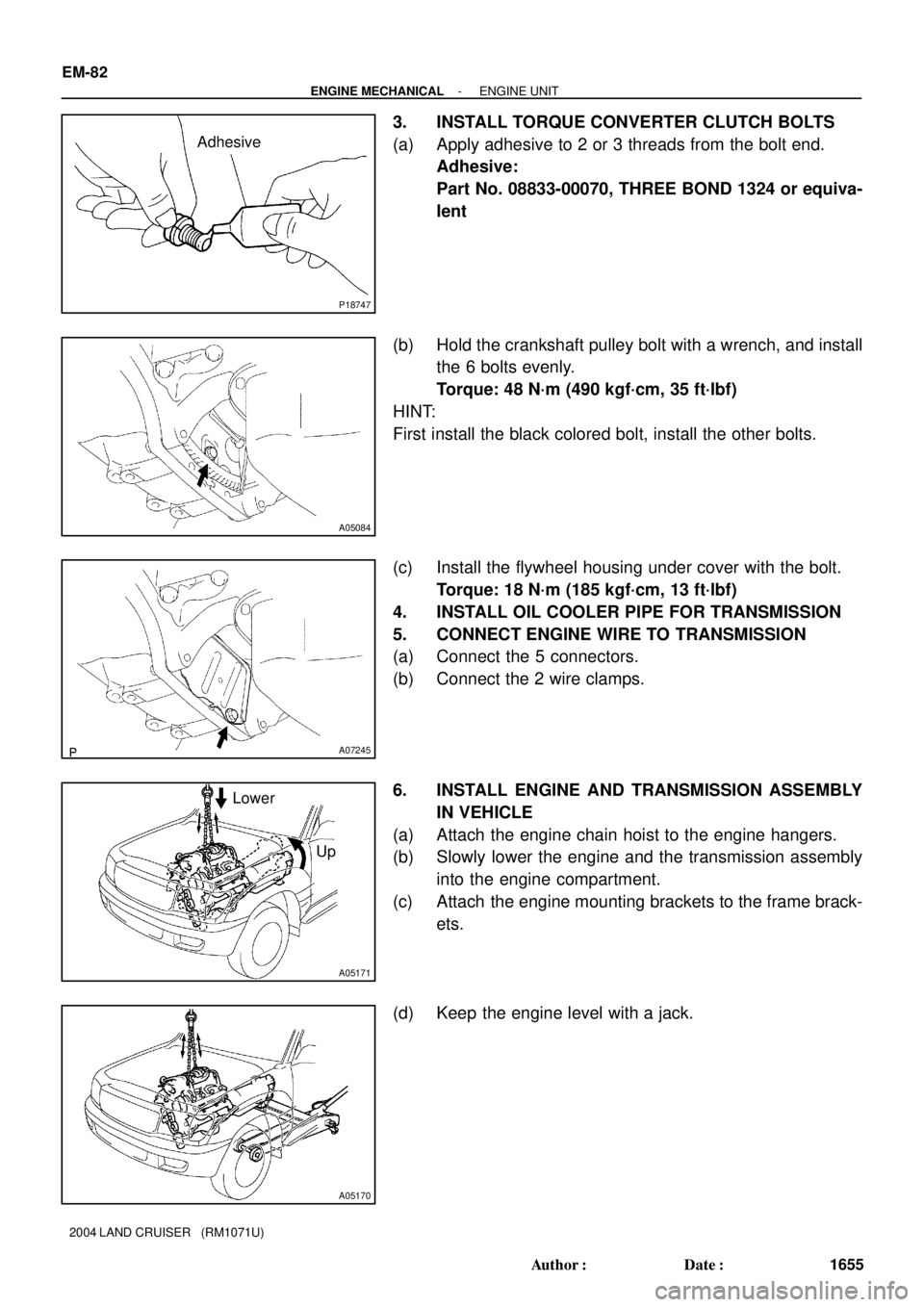
3. INSTALL TORQUE CONVERTER CLUTCH BOLTS
(a) Apply adhesive to 2 or 3 threads from the bolt end.
Adhesive:
Part No. 08833-00070, THREE BOND 1324 or equiva-
lent
(b) Hold the crankshaft pulley bolt with a wrench, and install
the 6 bolts evenly.
Torque: 48 N´m (490 kgf´cm, 35 ft´lbf)
HINT:
First install the black colored bolt, install the other bolts.
(c) Install the flywheel housing under cover with the bolt.
Torque: 18 N´m (185 kgf´cm, 13 ft´lbf)
4. INSTALL OIL COOLER PIPE FOR TRANSMISSION
5. CONNECT ENGINE WIRE TO TRANSMISSION
(a) Connect the 5 connectors.
(b) Connect the 2 wire clamps.
6. INSTALL ENGINE AND TRANSMISSION ASSEMBLY
IN VEHICLE
(a) Attach the engine chain hoist to the engine hangers.
(b) Slowly lower the engine and the transmission assembly
into the engine compartment.
(c) Attach the engine mounting brackets to the frame brack-
ets.
(d) Keep the engine level with a jack.
Page 1876 of 3115

EM-84
- ENGINE MECHANICALENGINE UNIT
1657 Author�: Date�:
2004 LAND CRUISER (RM1071U)
13. CONNECT HOSES, WIRES, CONNECTORS, CLAMPS,
GROMMET AND CABLES
(a) Connect the 2 PS air hoses to the hose clamp on the No.3
RH timing belt cover.
(b) Connect the generator wire.
(c) Connect the generator connector.
(d) Connect the hose clamp for the PS air hose.
(e) Connect the PS air hose to upper intake manifold.
(f) Connect the 2 heater hoses.
(g) Connect the engine wire clamp to the bracket on the cowl
panel.
(h) Connect the engine wire grommet to the cowl panel.
(i) Connect the ground strap connector.
(j) Connect the fuel main hose and the clamps.
(k) Connect the fuel return hose and the clamp.
(l) Connect the air inlet hose to the charcoal canister.
(m) Connect the EVAP hose to the charcoal canister.
(n) Connect the engine wire to the clamp on the right fender
apron.
(o) Connect the clamp on battery negative (-) cable to the
relay box.
(p) Connect the battery negative (-) cable to the right fender
apron.
(q) Connect the battery positive (+) terminal cable.
14. CONNECT ENGINE WIRE TO CABIN
(a) Connect the 3 wire harness connectors.
(b) Install the ECM with the 3 screws.
(c) Connect the 3 connectors to the ECM.
(d) Install the glove compartment door.
(e) Install the lower No.2 panel.
15. INSTALL FAN PULLEY, FAN, FLUID COUPLING AND
GENERATOR DRIVE BELT
(a) Temporarily install the fan pulley, the fan and the fluid cou-
pling assembly with the 4 nuts.
(b) Install the generator drive belt. (See page CH-16)
(c) Tighten the 4 nuts holding the fluid coupling to the fan
bracket.
16. INSTALL RADIATOR AND FAN SHROUD
(a) Place the fan shroud in the installation position.
(b) Install the radiator with the 2 support collars, the 2 nuts
and the 2 bolts.
(c) Connect the 2 A/T oil cooler hoses to the radiator.
(d) Install the lower radiator hose.
(e) Attach the lower side of the fan shroud to the brackets of
the radiator, and install the fan shroud with the 2 bolts.
(f) Install the 2 brackets on the wire to the radiator with the
2 bolts.
(g) Install the 2 clamps on the A/C discharge tube to the
brackets on the wire with the 2 nuts.
Page 1877 of 3115
- ENGINE MECHANICALENGINE UNIT
EM-85
1658 Author�: Date�:
2004 LAND CRUISER (RM1071U)
(h) Connect the upper radiator hose to the front water bypass
joint.
17. INSTALL RADIATOR RESERVOIR
(a) Install the grommet to the reservoir.
(b) Attach the lower side of the reservoir to the fan shroud.
(c) Install the reservoir with the 2 bolts.
(d) Connect the reservoir hose to the radiator.
(e) Install the clamp on the wire to the reservoir.
18. INSTALL AIR CLEANER CAP AND INTAKE AIR CON-
NECTOR PIPE ASSEMBLY
19. INSTALL BATTERY
20. FILL WITH ENGINE COOLANT (See page CO-2)
21. FILL WITH ENGINE OIL (See page LU-2)
22. START ENGINE AND CHECK FOR LEAKS
23. INSTALL V-BANK COVER
24. INSTALL ENGINE UNDER COVERS
25. INSTALL HOOD
26. PERFORM ROAD TEST
Check for abnormal noise, shock, slippage, and make sure the
shift points is correct and operation is smooth.
27. RECHECK ENGINE COOLANT AND OIL LEVELS