Page 1831 of 3115
EM0L1-08
A03191
SST
A03192
EM-44
- ENGINE MECHANICALCYLINDER HEAD
1617 Author�: Date�:
2004 LAND CRUISER (RM1071U)
DISASSEMBLY
1. REMOVE VALVE LIFTERS AND SHIMS
HINT:
Arrange the valve lifters and the shims in correct order.
2. REMOVE VALVES
(a) Using SST, compress the valve spring and remove the 2
keepers.
SST 09202-70020
(b) Remove the spring retainer.
(c) Remove the valve spring.
(d) Remove the valve.
(e) Remove the spring seat.
HINT:
Arrange the valves, the valve springs, the spring seats and the
spring retainers incorrect order.
(f) Using needle-nose pliers, remove the oil seal.
Page 1832 of 3115
EM0L2-07
A03194
A03193
EM6323
EM6324
P21861
- ENGINE MECHANICALCYLINDER HEAD
EM-45
1618 Author�: Date�:
2004 LAND CRUISER (RM1071U)
INSPECTION
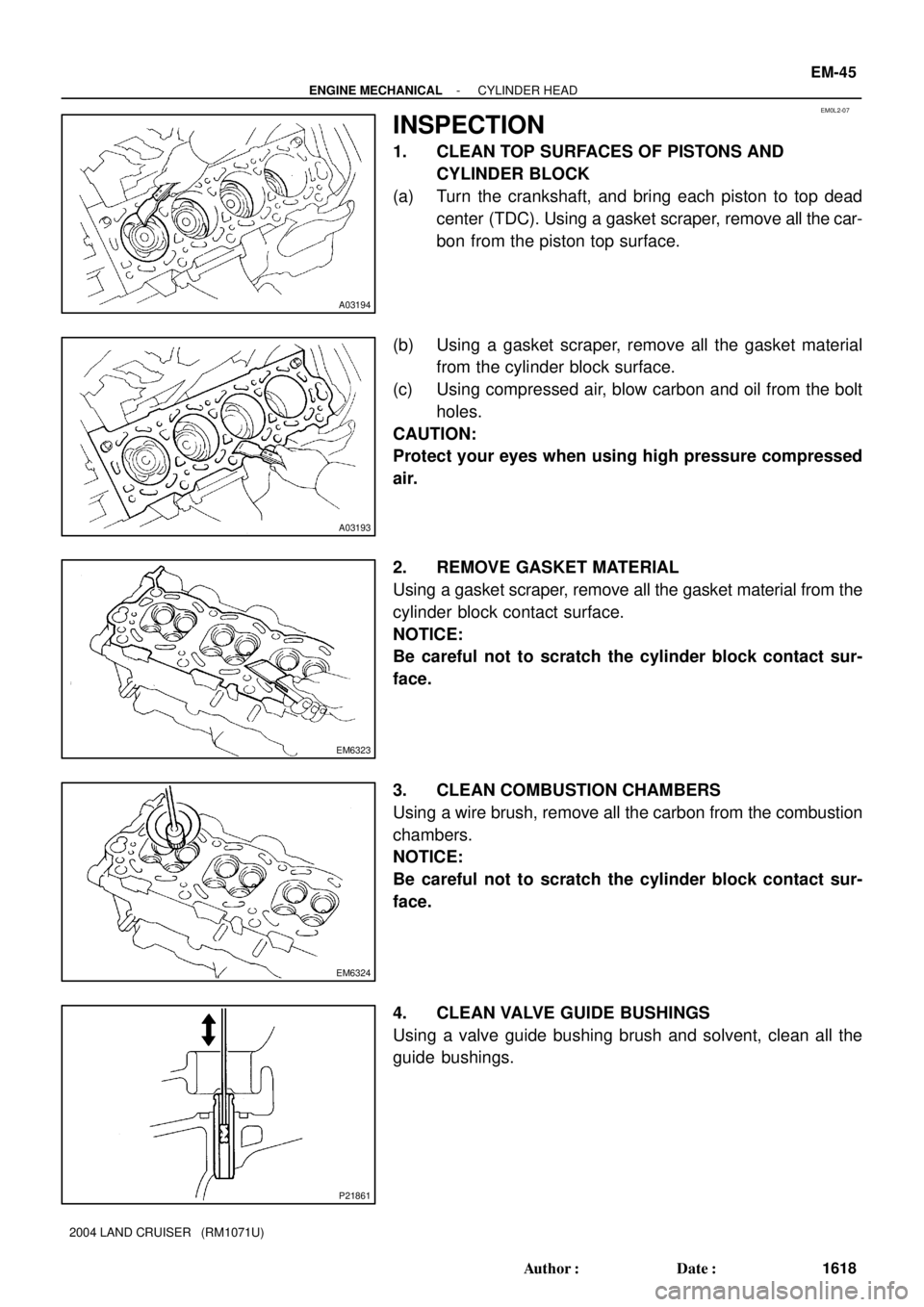
1. CLEAN TOP SURFACES OF PISTONS AND
CYLINDER BLOCK
(a) Turn the crankshaft, and bring each piston to top dead
center (TDC). Using a gasket scraper, remove all the car-
bon from the piston top surface.
(b) Using a gasket scraper, remove all the gasket material
from the cylinder block surface.
(c) Using compressed air, blow carbon and oil from the bolt
holes.
CAUTION:
Protect your eyes when using high pressure compressed
air.
2. REMOVE GASKET MATERIAL
Using a gasket scraper, remove all the gasket material from the
cylinder block contact surface.
NOTICE:
Be careful not to scratch the cylinder block contact sur-
face.
3. CLEAN COMBUSTION CHAMBERS
Using a wire brush, remove all the carbon from the combustion
chambers.
NOTICE:
Be careful not to scratch the cylinder block contact sur-
face.
4. CLEAN VALVE GUIDE BUSHINGS
Using a valve guide bushing brush and solvent, clean all the
guide bushings.
Page 1834 of 3115
P21862
Z00052
Z00054
- ENGINE MECHANICALCYLINDER HEAD
EM-47
1620 Author�: Date�:
2004 LAND CRUISER (RM1071U)
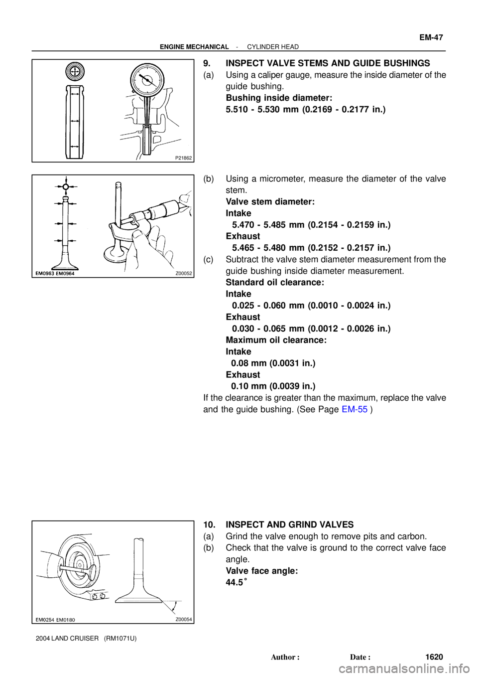
9. INSPECT VALVE STEMS AND GUIDE BUSHINGS
(a) Using a caliper gauge, measure the inside diameter of the
guide bushing.
Bushing inside diameter:
5.510 - 5.530 mm (0.2169 - 0.2177 in.)
(b) Using a micrometer, measure the diameter of the valve
stem.
Valve stem diameter:
Intake
5.470 - 5.485 mm (0.2154 - 0.2159 in.)
Exhaust
5.465 - 5.480 mm (0.2152 - 0.2157 in.)
(c) Subtract the valve stem diameter measurement from the
guide bushing inside diameter measurement.
Standard oil clearance:
Intake
0.025 - 0.060 mm (0.0010 - 0.0024 in.)
Exhaust
0.030 - 0.065 mm (0.0012 - 0.0026 in.)
Maximum oil clearance:
Intake
0.08 mm (0.0031 in.)
Exhaust
0.10 mm (0.0039 in.)
If the clearance is greater than the maximum, replace the valve
and the guide bushing. (See Page EM-55)
10. INSPECT AND GRIND VALVES
(a) Grind the valve enough to remove pits and carbon.
(b) Check that the valve is ground to the correct valve face
angle.
Valve face angle:
44.5°
Page 1838 of 3115
A05519
EM3322
A05520
Plastigage
A05522
- ENGINE MECHANICALCYLINDER HEAD
EM-51
1624 Author�: Date�:
2004 LAND CRUISER (RM1071U)
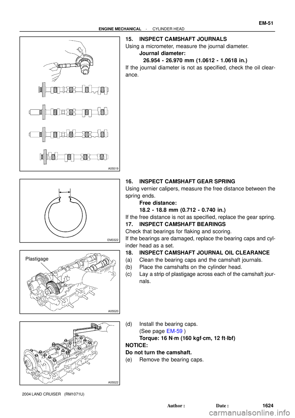
15. INSPECT CAMSHAFT JOURNALS
Using a micrometer, measure the journal diameter.
Journal diameter:
26.954 - 26.970 mm (1.0612 - 1.0618 in.)
If the journal diameter is not as specified, check the oil clear-
ance.
16. INSPECT CAMSHAFT GEAR SPRING
Using vernier calipers, measure the free distance between the
spring ends.
Free distance:
18.2 - 18.8 mm (0.712 - 0.740 in.)
If the free distance is not as specified, replace the gear spring.
17. INSPECT CAMSHAFT BEARINGS
Check that bearings for flaking and scoring.
If the bearings are damaged, replace the bearing caps and cyl-
inder head as a set.
18. INSPECT CAMSHAFT JOURNAL OIL CLEARANCE
(a) Clean the bearing caps and the camshaft journals.
(b) Place the camshafts on the cylinder head.
(c) Lay a strip of plastigage across each of the camshaft jour-
nals.
(d) Install the bearing caps.
(See page EM-59)
Torque: 16 N´m (160 kgf´cm, 12 ft´lbf)
NOTICE:
Do not turn the camshaft.
(e) Remove the bearing caps.
Page 1839 of 3115
A05521
A05523
A05524
EM-52
- ENGINE MECHANICALCYLINDER HEAD
1625 Author�: Date�:
2004 LAND CRUISER (RM1071U)
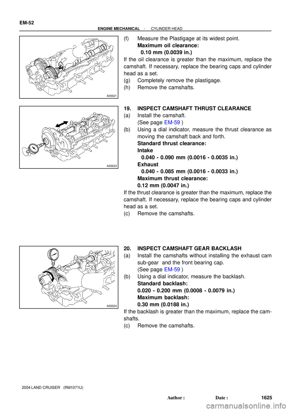
(f) Measure the Plastigage at its widest point.
Maximum oil clearance:
0.10 mm (0.0039 in.)
If the oil clearance is greater than the maximum, replace the
camshaft. If necessary, replace the bearing caps and cylinder
head as a set.
(g) Completely remove the plastigage.
(h) Remove the camshafts.
19. INSPECT CAMSHAFT THRUST CLEARANCE
(a) Install the camshaft.
(See page EM-59)
(b) Using a dial indicator, measure the thrust clearance as
moving the camshaft back and forth.
Standard thrust clearance:
Intake
0.040 - 0.090 mm (0.0016 - 0.0035 in.)
Exhaust
0.040 - 0.085 mm (0.0016 - 0.0033 in.)
Maximum thrust clearance:
0.12 mm (0.0047 in.)
If the thrust clearance is greater than the maximum, replace the
camshaft. If necessary, replace the bearing caps and cylinder
head as a set.
(c) Remove the camshafts.
20. INSPECT CAMSHAFT GEAR BACKLASH
(a) Install the camshafts without installing the exhaust cam
sub-gear and the front bearing cap.
(See page EM-59)
(b) Using a dial indicator, measure the backlash.
Standard backlash:
0.020 - 0.200 mm (0.0008 - 0.0079 in.)
Maximum backlash:
0.30 mm (0.0188 in.)
If the backlash is greater than the maximum, replace the cam-
shafts.
(c) Remove the camshafts.
Page 1840 of 3115
A03209
A03201
12.3 - 12.7 mm
A05499
- ENGINE MECHANICALCYLINDER HEAD
EM-53
1626 Author�: Date�:
2004 LAND CRUISER (RM1071U)
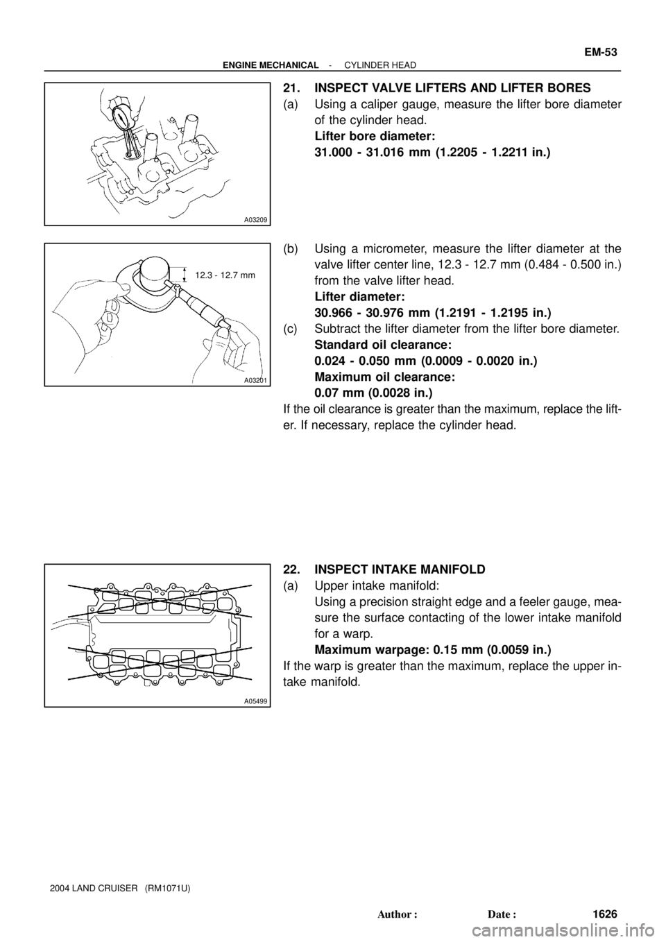
21. INSPECT VALVE LIFTERS AND LIFTER BORES
(a) Using a caliper gauge, measure the lifter bore diameter
of the cylinder head.
Lifter bore diameter:
31.000 - 31.016 mm (1.2205 - 1.2211 in.)
(b) Using a micrometer, measure the lifter diameter at the
valve lifter center line, 12.3 - 12.7 mm (0.484 - 0.500 in.)
from the valve lifter head.
Lifter diameter:
30.966 - 30.976 mm (1.2191 - 1.2195 in.)
(c) Subtract the lifter diameter from the lifter bore diameter.
Standard oil clearance:
0.024 - 0.050 mm (0.0009 - 0.0020 in.)
Maximum oil clearance:
0.07 mm (0.0028 in.)
If the oil clearance is greater than the maximum, replace the lift-
er. If necessary, replace the cylinder head.
22. INSPECT INTAKE MANIFOLD
(a) Upper intake manifold:
Using a precision straight edge and a feeler gauge, mea-
sure the surface contacting of the lower intake manifold
for a warp.
Maximum warpage: 0.15 mm (0.0059 in.)
If the warp is greater than the maximum, replace the upper in-
take manifold.
Page 1843 of 3115
A05563
RH Cylinder Head
LH Cylinder Head 2UR
2UL
A05714
RH Cylinder Head
LH Cylinder Head
179
4
6
5
3
10
8
217
96
5
3
10
8
2
1
4
Front EM-60
- ENGINE MECHANICALCYLINDER HEAD
1633 Author�: Date�:
2004 LAND CRUISER (RM1071U)
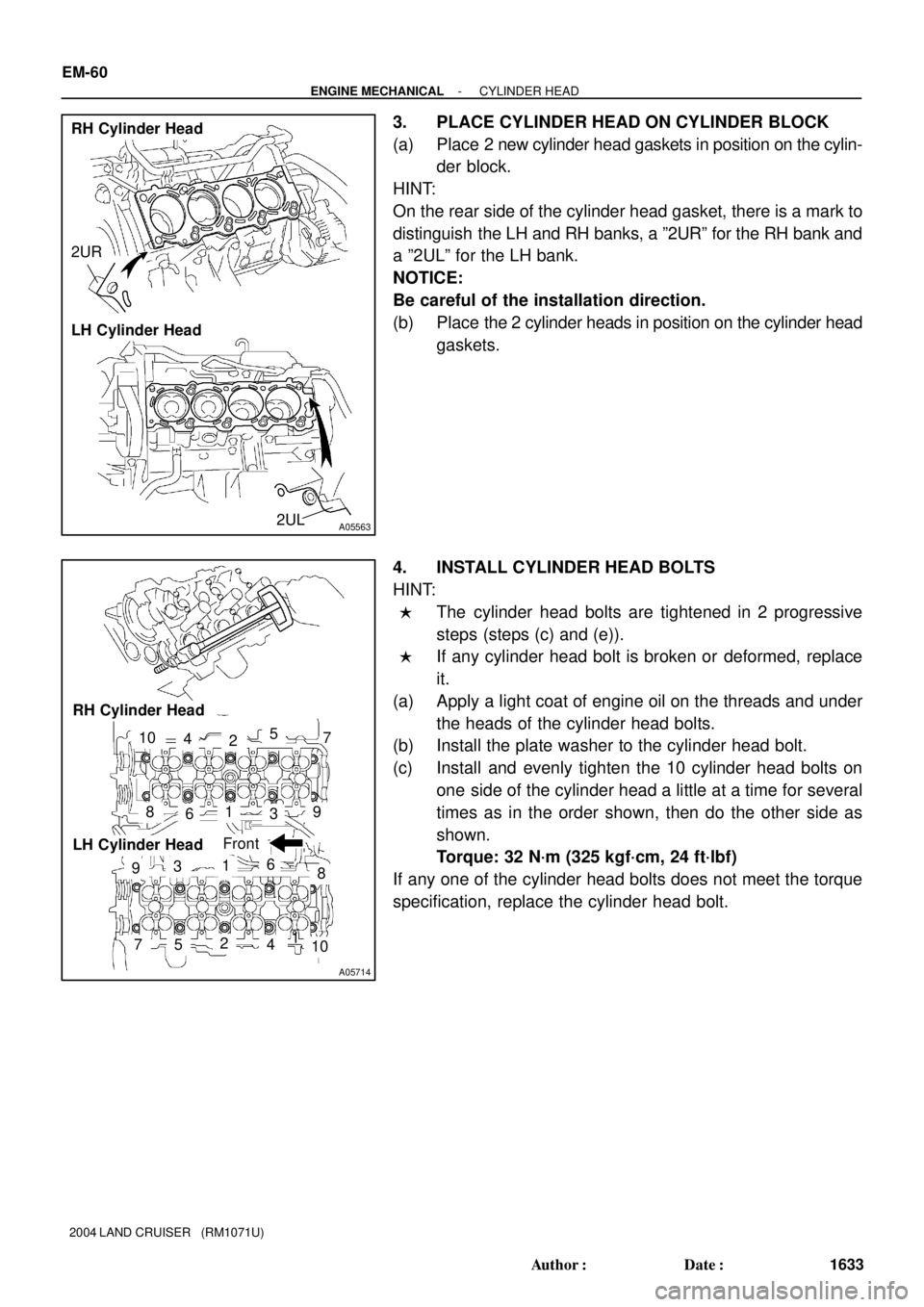
3. PLACE CYLINDER HEAD ON CYLINDER BLOCK
(a) Place 2 new cylinder head gaskets in position on the cylin-
der block.
HINT:
On the rear side of the cylinder head gasket, there is a mark to
distinguish the LH and RH banks, a º2URº for the RH bank and
a º2ULº for the LH bank.
NOTICE:
Be careful of the installation direction.
(b) Place the 2 cylinder heads in position on the cylinder head
gaskets.
4. INSTALL CYLINDER HEAD BOLTS
HINT:
�The cylinder head bolts are tightened in 2 progressive
steps (steps (c) and (e)).
�If any cylinder head bolt is broken or deformed, replace
it.
(a) Apply a light coat of engine oil on the threads and under
the heads of the cylinder head bolts.
(b) Install the plate washer to the cylinder head bolt.
(c) Install and evenly tighten the 10 cylinder head bolts on
one side of the cylinder head a little at a time for several
times as in the order shown, then do the other side as
shown.
Torque: 32 N´m (325 kgf´cm, 24 ft´lbf)
If any one of the cylinder head bolts does not meet the torque
specification, replace the cylinder head bolt.
Page 1844 of 3115
A04473
RH Cylinder Head
LH Cylinder HeadA
A
A11159
Painted Mark90°
180°
A02888
A02861
- ENGINE MECHANICALCYLINDER HEAD
EM-61
1634 Author�: Date�:
2004 LAND CRUISER (RM1071U)
NOTICE:
Do not drop the plate washer of the cylinder head bolt into
A area in the illustration. It will fall down to the oil pan
through the cylinder head and the cylinder block.
(d) Mark the front of the cylinder head bolt head with paint.
(e) Retighten the cylinder head bolts by 90° only for the first
time.
(f) Then retighten them by 90° further for the second time.
(g) Check that the painted mark is now at a 180° angle to the
front.
5. INSTALL SPARK PLUGS
6. ASSEMBLE EXHAUST CAMSHAFT
(a) Install the camshaft gear spring, the camshaft sub-gear
and the wave washer.
HINT:
Attach the pins on the gears to the gear spring ends.
(b) Using snap ring pliers, install the snap ring.