Page 2852 of 3115
F04867
Tilt Steering
ShaftBolt
Plate Washer
SST
F08835
Screw
Extractor
F04863
- STEERINGPOWER TILT AND POWER TELESCOPIC STEERING
COLUMNSR-31
2240 Author�: Date�:
2004 LAND CRUISER (RM1071U)
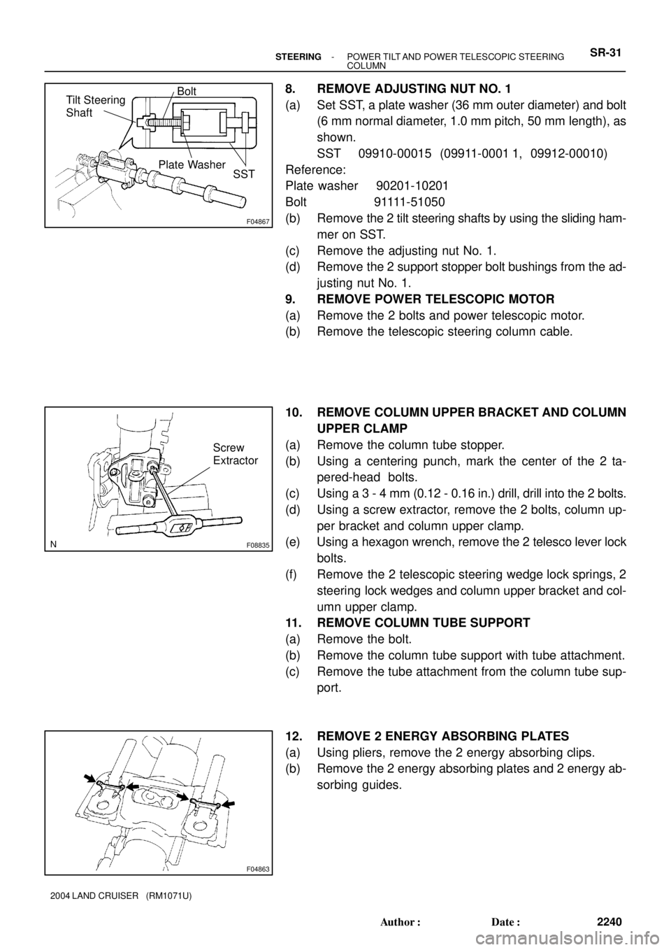
8. REMOVE ADJUSTING NUT NO. 1
(a) Set SST, a plate washer (36 mm outer diameter) and bolt
(6 mm normal diameter, 1.0 mm pitch, 50 mm length), as
shown.
SST 09910-00015 (09911-0001 1, 09912-00010)
Reference:
Plate washer 90201-10201
Bolt 91111-51050
(b) Remove the 2 tilt steering shafts by using the sliding ham-
mer on SST.
(c) Remove the adjusting nut No. 1.
(d) Remove the 2 support stopper bolt bushings from the ad-
justing nut No. 1.
9. REMOVE POWER TELESCOPIC MOTOR
(a) Remove the 2 bolts and power telescopic motor.
(b) Remove the telescopic steering column cable.
10. REMOVE COLUMN UPPER BRACKET AND COLUMN
UPPER CLAMP
(a) Remove the column tube stopper.
(b) Using a centering punch, mark the center of the 2 ta-
pered-head bolts.
(c) Using a 3 - 4 mm (0.12 - 0.16 in.) drill, drill into the 2 bolts.
(d) Using a screw extractor, remove the 2 bolts, column up-
per bracket and column upper clamp.
(e) Using a hexagon wrench, remove the 2 telesco lever lock
bolts.
(f) Remove the 2 telescopic steering wedge lock springs, 2
steering lock wedges and column upper bracket and col-
umn upper clamp.
11. REMOVE COLUMN TUBE SUPPORT
(a) Remove the bolt.
(b) Remove the column tube support with tube attachment.
(c) Remove the tube attachment from the column tube sup-
port.
12. REMOVE 2 ENERGY ABSORBING PLATES
(a) Using pliers, remove the 2 energy absorbing clips.
(b) Remove the 2 energy absorbing plates and 2 energy ab-
sorbing guides.
Page 2863 of 3115
F16017
Steering Column
Upper Cover
New Marked
Line
Steering Wheel
R00429
Marked Line
F16018
- STEERINGSTEERING WHEEL
SR-1 1
2220 Author�: Date�:
2004 LAND CRUISER (RM1071U)
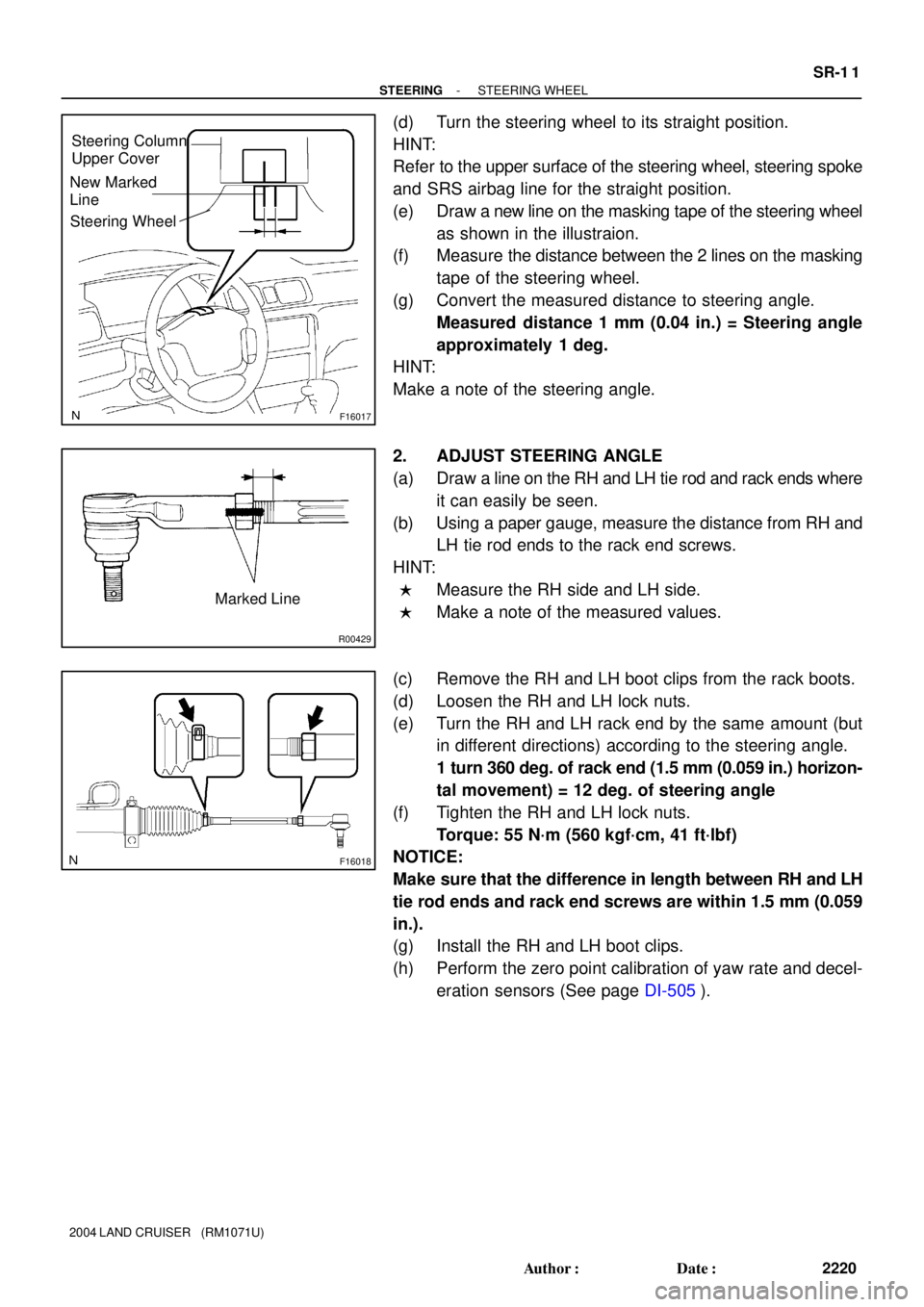
(d) Turn the steering wheel to its straight position.
HINT:
Refer to the upper surface of the steering wheel, steering spoke
and SRS airbag line for the straight position.
(e) Draw a new line on the masking tape of the steering wheel
as shown in the illustraion.
(f) Measure the distance between the 2 lines on the masking
tape of the steering wheel.
(g) Convert the measured distance to steering angle.
Measured distance 1 mm (0.04 in.) = Steering angle
approximately 1 deg.
HINT:
Make a note of the steering angle.
2. ADJUST STEERING ANGLE
(a) Draw a line on the RH and LH tie rod and rack ends where
it can easily be seen.
(b) Using a paper gauge, measure the distance from RH and
LH tie rod ends to the rack end screws.
HINT:
�Measure the RH side and LH side.
�Make a note of the measured values.
(c) Remove the RH and LH boot clips from the rack boots.
(d) Loosen the RH and LH lock nuts.
(e) Turn the RH and LH rack end by the same amount (but
in different directions) according to the steering angle.
1 turn 360 deg. of rack end (1.5 mm (0.059 in.) horizon-
tal movement) = 12 deg. of steering angle
(f) Tighten the RH and LH lock nuts.
Torque: 55 N´m (560 kgf´cm, 41 ft´lbf)
NOTICE:
Make sure that the difference in length between RH and LH
tie rod ends and rack end screws are within 1.5 mm (0.059
in.).
(g) Install the RH and LH boot clips.
(h) Perform the zero point calibration of yaw rate and decel-
eration sensors (See page DI-505).
Page 2931 of 3115
R10354
Clearance
SST
F05099
Outboard
Joint Side
F05237
SA-32
- SUSPENSION AND AXLEFRONT DRIVE SHAFT
1982 Author�: Date�:
2004 LAND CRUISER (RM1071U)
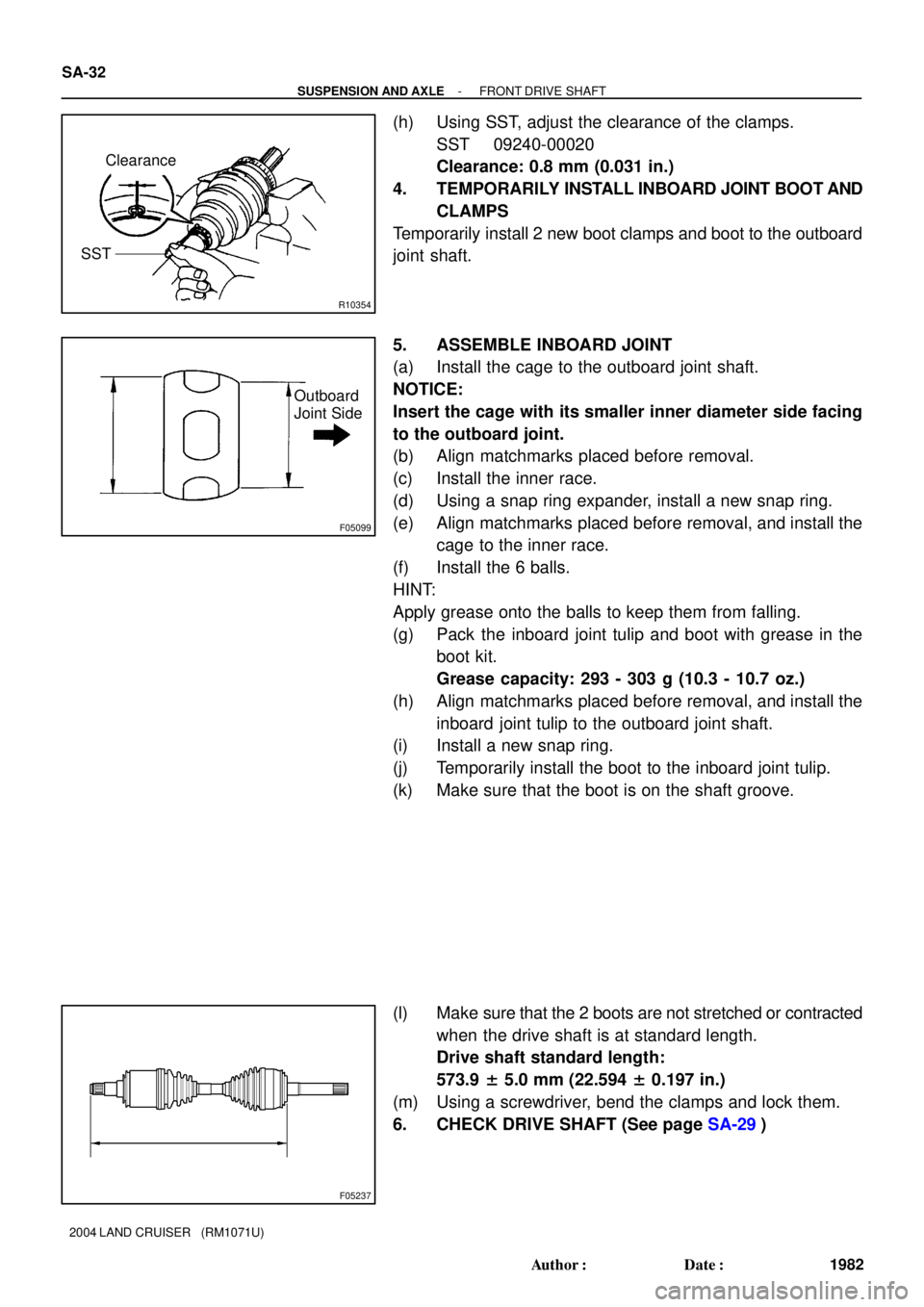
(h) Using SST, adjust the clearance of the clamps.
SST 09240-00020
Clearance: 0.8 mm (0.031 in.)
4. TEMPORARILY INSTALL INBOARD JOINT BOOT AND
CLAMPS
Temporarily install 2 new boot clamps and boot to the outboard
joint shaft.
5. ASSEMBLE INBOARD JOINT
(a) Install the cage to the outboard joint shaft.
NOTICE:
Insert the cage with its smaller inner diameter side facing
to the outboard joint.
(b) Align matchmarks placed before removal.
(c) Install the inner race.
(d) Using a snap ring expander, install a new snap ring.
(e) Align matchmarks placed before removal, and install the
cage to the inner race.
(f) Install the 6 balls.
HINT:
Apply grease onto the balls to keep them from falling.
(g) Pack the inboard joint tulip and boot with grease in the
boot kit.
Grease capacity: 293 - 303 g (10.3 - 10.7 oz.)
(h) Align matchmarks placed before removal, and install the
inboard joint tulip to the outboard joint shaft.
(i) Install a new snap ring.
(j) Temporarily install the boot to the inboard joint tulip.
(k) Make sure that the boot is on the shaft groove.
(l) Make sure that the 2 boots are not stretched or contracted
when the drive shaft is at standard length.
Drive shaft standard length:
573.9 ± 5.0 mm (22.594 ± 0.197 in.)
(m) Using a screwdriver, bend the clamps and lock them.
6. CHECK DRIVE SHAFT (See page SA-29)
Page 2952 of 3115
SA14Y-02
F05244
F05245
B
F05246
A
- SUSPENSION AND AXLEFRONT TORSION BAR SPRING
SA-67
2017 Author�: Date�:
2004 LAND CRUISER (RM1071U)
INSTALLATION
1. INSTALL TORQUE ARM
Install the bolt, torque arm and 2 nuts.
Torque: 225 N´m (2,300 kgf´cm, 166 ft´lbf)
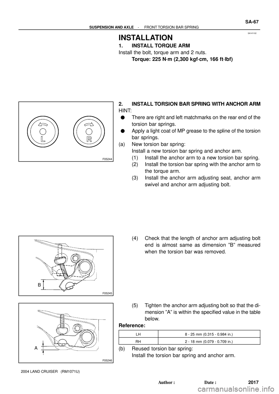
2. INSTALL TORSION BAR SPRING WITH ANCHOR ARM
HINT:
�There are right and left matchmarks on the rear end of the
torsion bar springs.
�Apply a light coat of MP grease to the spline of the torsion
bar springs.
(a) New torsion bar spring:
Install a new torsion bar spring and anchor arm.
(1) Install the anchor arm to a new torsion bar spring.
(2) Install the torsion bar spring with the anchor arm to
the torque arm.
(3) Install the anchor arm adjusting seat, anchor arm
swivel and anchor arm adjusting bolt.
(4) Check that the length of anchor arm adjusting bolt
end is almost same as dimension ºBº measured
when the torsion bar was removed.
(5) Tighten the anchor arm adjusting bolt so that the di-
mension ºAº is within the specified value in the table
below.
Reference:
LH8 - 25 mm (0.315 - 0.984 in.)
RH2 - 18 mm (0.079 - 0.709 in.)
(b) Reused torsion bar spring:
Install the torsion bar spring and anchor arm.
Page 2963 of 3115
SA3213
AB
CD
Front
F05208
- SUSPENSION AND AXLEFRONT WHEEL ALIGNMENT
SA-9
1959 Author�: Date�:
2004 LAND CRUISER (RM1071U)
(d) Torque the front and/or rear adjusting cam nuts.
Torque: 98 N´m (1,000 kgf´cm, 72 ft´lbf)
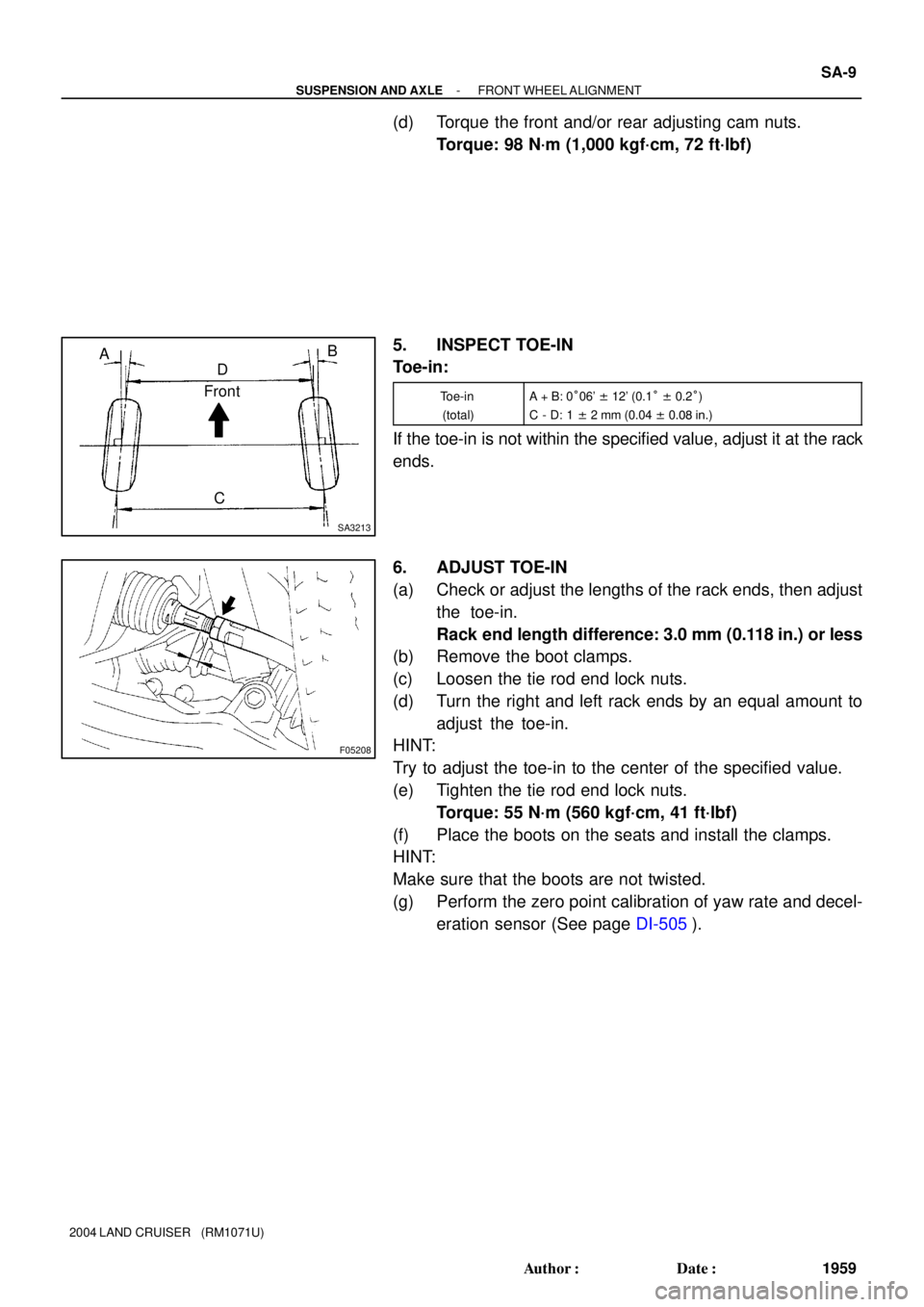
5. INSPECT TOE-IN
Toe-in:
Toe-in
(total)A + B: 0°06' ± 12' (0.1° ± 0.2°)
C - D: 1 ± 2 mm (0.04 ± 0.08 in.)
If the toe-in is not within the specified value, adjust it at the rack
ends.
6. ADJUST TOE-IN
(a) Check or adjust the lengths of the rack ends, then adjust
the toe-in.
Rack end length difference: 3.0 mm (0.118 in.) or less
(b) Remove the boot clamps.
(c) Loosen the tie rod end lock nuts.
(d) Turn the right and left rack ends by an equal amount to
adjust the toe-in.
HINT:
Try to adjust the toe-in to the center of the specified value.
(e) Tighten the tie rod end lock nuts.
Torque: 55 N´m (560 kgf´cm, 41 ft´lbf)
(f) Place the boots on the seats and install the clamps.
HINT:
Make sure that the boots are not twisted.
(g) Perform the zero point calibration of yaw rate and decel-
eration sensor (See page DI-505).
Page 2964 of 3115
SA0028
AB
FrontBA
A: Inside
B: Outside
F05200
SA-10
- SUSPENSION AND AXLEFRONT WHEEL ALIGNMENT
1960 Author�: Date�:
2004 LAND CRUISER (RM1071U)
7. INSPECT AND ADJUST WHEEL ANGLE
(a) Turn the steering wheel fully, and measure the turning
angle.
Wheel turning angle:
Inside wheel36°42' (33°42' - 36°42')
36.7° (33.7° - 36.7°)
Outside wheel: Reference32°36'
32.6°
If the right and left inside wheel angles differ from the specified
value, check the right and left rack end lengths.
(b) When toe-in is normal after inspection, adjust wheel
angle with the knuckle stopper bolt of the lower suspen-
sion arm.
Torque: 44 N´m (450 kgf´cm, 32 ft´lbf)
Page 2972 of 3115
F05114
SST
SST
- SUSPENSION AND AXLEREAR AXLE SHAFT
SA-91
2041 Author�: Date�:
2004 LAND CRUISER (RM1071U)
7. INSTALL ABS SPEED SENSOR ROTOR AND BEAR-
ING RETAINER
Using SST and a press, install a new ABS speed sensor rotor
and bearing retainer.
SST 09631-12090, 09950-60020 (09951-01030)
Standard length: 170.7 ± 1.0 mm (6.720 ± 0.039 in.)
Page 3024 of 3115
SA161-04
RA0225
Z15288
R13849
RA0192
SA-148
- SUSPENSION AND AXLEREAR DIFFERENTIAL CARRIER (w/ LSD)
2098 Author�: Date�:
2004 LAND CRUISER (RM1071U)
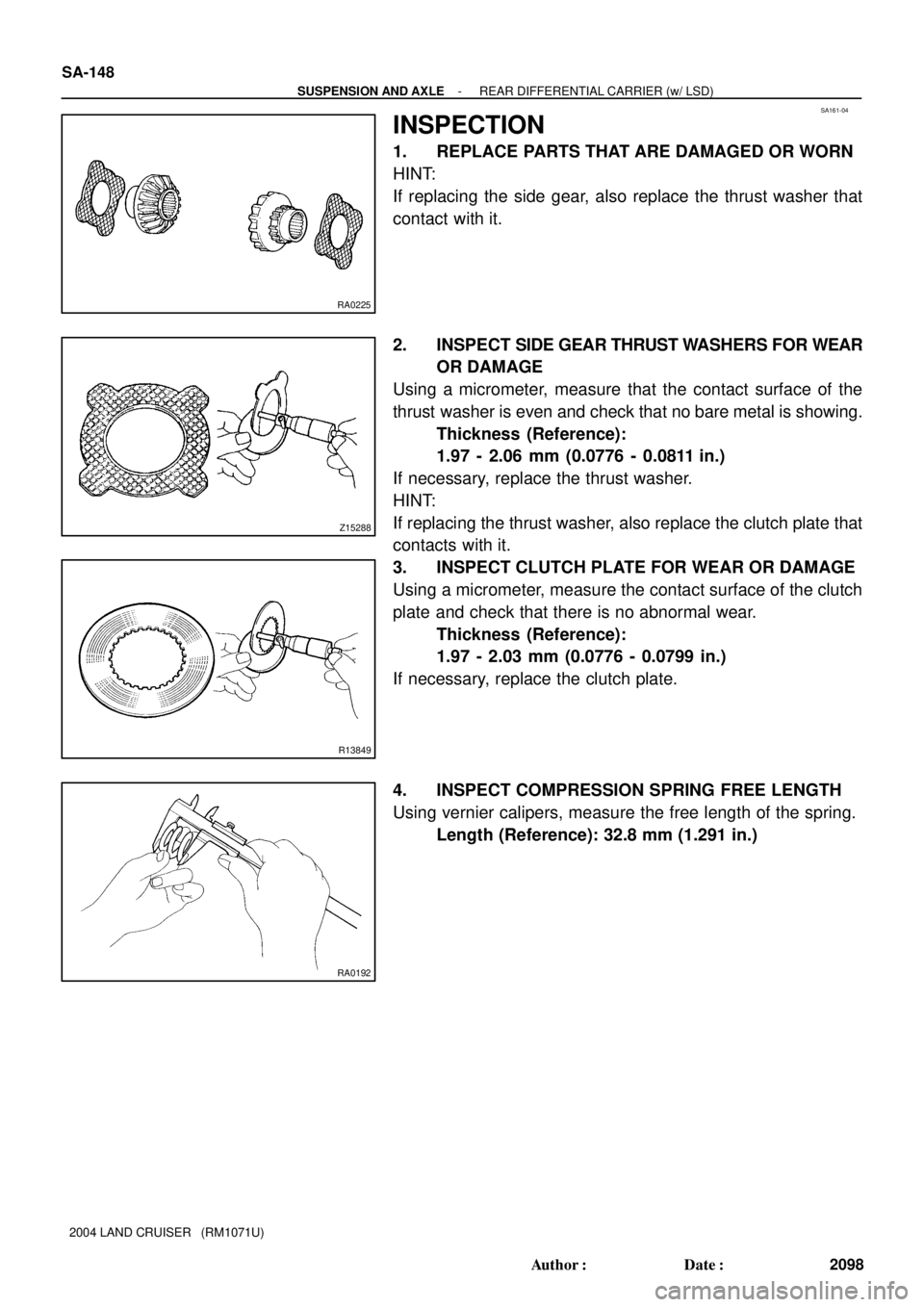
INSPECTION
1. REPLACE PARTS THAT ARE DAMAGED OR WORN
HINT:
If replacing the side gear, also replace the thrust washer that
contact with it.
2. INSPECT SIDE GEAR THRUST WASHERS FOR WEAR
OR DAMAGE
Using a micrometer, measure that the contact surface of the
thrust washer is even and check that no bare metal is showing.
Thickness (Reference):
1.97 - 2.06 mm (0.0776 - 0.0811 in.)
If necessary, replace the thrust washer.
HINT:
If replacing the thrust washer, also replace the clutch plate that
contacts with it.
3. INSPECT CLUTCH PLATE FOR WEAR OR DAMAGE
Using a micrometer, measure the contact surface of the clutch
plate and check that there is no abnormal wear.
Thickness (Reference):
1.97 - 2.03 mm (0.0776 - 0.0799 in.)
If necessary, replace the clutch plate.
4. INSPECT COMPRESSION SPRING FREE LENGTH
Using vernier calipers, measure the free length of the spring.
Length (Reference): 32.8 mm (1.291 in.)