Page 2671 of 3115

B04933
New Gasket
B04934
Fulcrum
Length
30 cm
SST
B04895
SST Fulcrum
Length
30 cm
B02714
CORRECT
WRONG
Delivery Pipe O-Ring
- SFISFI SYSTEM
SF-3
1702 Author�: Date�:
2004 LAND CRUISER (RM1071U)
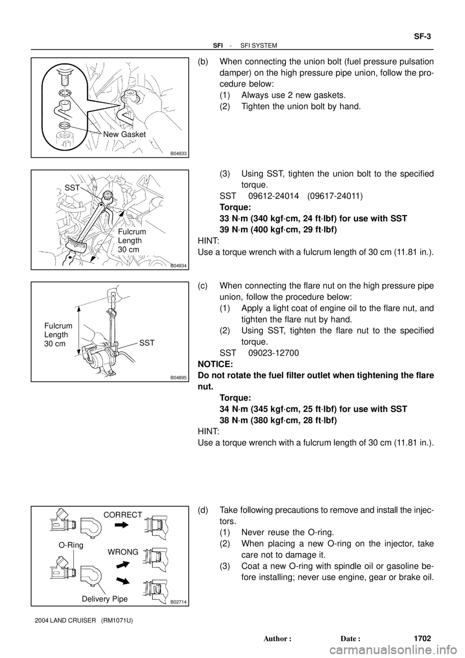
(b) When connecting the union bolt (fuel pressure pulsation
damper) on the high pressure pipe union, follow the pro-
cedure below:
(1) Always use 2 new gaskets.
(2) Tighten the union bolt by hand.
(3) Using SST, tighten the union bolt to the specified
torque.
SST 09612-24014 (09617-24011)
Torque:
33 N´m (340 kgf´cm, 24 ft´lbf) for use with SST
39 N´m (400 kgf´cm, 29 ft´lbf)
HINT:
Use a torque wrench with a fulcrum length of 30 cm (11.81 in.).
(c) When connecting the flare nut on the high pressure pipe
union, follow the procedure below:
(1) Apply a light coat of engine oil to the flare nut, and
tighten the flare nut by hand.
(2) Using SST, tighten the flare nut to the specified
torque.
SST 09023-12700
NOTICE:
Do not rotate the fuel filter outlet when tightening the flare
nut.
Torque:
34 N´m (345 kgf´cm, 25 ft´lbf) for use with SST
38 N´m (380 kgf´cm, 28 ft´lbf)
HINT:
Use a torque wrench with a fulcrum length of 30 cm (11.81 in.).
(d) Take following precautions to remove and install the injec-
tors.
(1) Never reuse the O-ring.
(2) When placing a new O-ring on the injector, take
care not to damage it.
(3) Coat a new O-ring with spindle oil or gasoline be-
fore installing; never use engine, gear or brake oil.
Page 2802 of 3115

P10588
Ohmmeter
Continuity
S02267
Ohmmeter
(A)(B)
Z00037
ST0019
P21088
Ohmmeter
No Continuity
- STARTINGSTARTER
ST-9
1825 Author�: Date�:
2004 LAND CRUISER (RM1071U)
7. INSPECT FIELD COIL FOR OPEN CIRCUIT
Using an ohmmeter, check that there is continuity between the
lead wire and field coil brush lead.
If there is no continuity, replace the field frame.
8. INSPECT SHUNT COIL FOR OPEN CIRCUIT
Using an ohmmeter, measure the resistance between shunt
coil terminals (A) and (B).
Resistance:
1.5 - 1.9 W at 20°C (68°F)
If the resistance is not as specified, replace the field frame.
9. INSPECT BRUSH LENGTH
Using vernier calipers, measure the brush length.
Standard length:
15.0 mm (0.591 in.)
Minimum length:
9.0 mm (0.354 in.)
If the length is less than minimum, replace the brush holder and
field frame.
10. INSPECT BRUSH SPRING LOAD
Using a pull scale, measure the spring load by pulling the spring
from the brush until they are separated.
Standard spring installed load:
21.5 - 27.5 N (2.2 - 2.8 kgf, 4.8 - 6.2 lbf)
Minimum spring installed load:
12.7 N (1.3 kgf, 2.9 lbf)
If the installed load is less than minimum, replace the brush
springs.
11. INSPECT BRUSH HOLDER INSULATION
Using an ohmmeter, check that there is no continuity between
the positive (+) and negative (-) brush holders.
If there is continuity, repair or replace the brush holder.
12. INSPECT GEAR TEETH
Check the gear teeth on the pinion gear, idle gear and the clutch
assembly for wear or damage.
If any damage is found, replace the gear or clutch assembly,
and also check the drive plate ring gear for wear or damage.
Page 2827 of 3115

F17185
SR0MO-08
F12855
SST
Fulcrum
Length
F04791
Stopper
- STEERINGPOWER STEERING GEAR
SR-65
2274 Author�: Date�:
2004 LAND CRUISER (RM1071U)
INSTALLATION
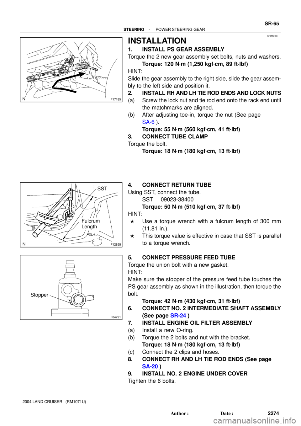
1. INSTALL PS GEAR ASSEMBLY
Torque the 2 new gear assembly set bolts, nuts and washers.
Torque: 120 N´m (1,250 kgf´cm, 89 ft´lbf)
HINT:
Slide the gear assembly to the right side, slide the gear assem-
bly to the left side and position it.
2. INSTALL RH AND LH TIE ROD ENDS AND LOCK NUTS
(a) Screw the lock nut and tie rod end onto the rack end until
the matchmarks are aligned.
(b) After adjusting toe-in, torque the nut (See page
SA-6).
Torque: 55 N´m (560 kgf´cm, 41 ft´lbf)
3. CONNECT TUBE CLAMP
Torque the bolt.
Torque: 18 N´m (180 kgf´cm, 13 ft´lbf)
4. CONNECT RETURN TUBE
Using SST, connect the tube.
SST 09023-38400
Torque: 50 N´m (510 kgf´cm, 37 ft´lbf)
HINT:
�Use a torque wrench with a fulcrum length of 300 mm
(11.81 in.).
�This torque value is effective in case that SST is parallel
to a torque wrench.
5. CONNECT PRESSURE FEED TUBE
Torque the union bolt with a new gasket.
HINT:
Make sure the stopper of the pressure feed tube touches the
PS gear assembly as shown in the illustration, then torque the
bolt.
Torque: 42 N´m (430 kgf´cm, 31 ft´lbf)
6. CONNECT NO. 2 INTERMEDIATE SHAFT ASSEMBLY
(See page SR-24)
7. INSTALL ENGINE OIL FILTER ASSEMBLY
(a) Install a new O-ring.
(b) Torque the 2 bolts and nut with the bracket.
Torque: 18 N´m (180 kgf´cm, 13 ft´lbf)
(c) Connect the 2 clips and hoses.
8. CONNECT RH AND LH TIE ROD ENDS (See page
SA-20)
9. INSTALL NO. 2 ENGINE UNDER COVER
Tighten the 6 bolts.
Page 2830 of 3115

F04837
Fulcrum
Length
SST
F10803
SST
F04832
Vinyl Tape
F04824
SST
F04823
- STEERINGPOWER STEERING GEAR
SR-61
2270 Author�: Date�:
2004 LAND CRUISER (RM1071U)
(d) Using SST, torque the stopper.
SST 09922-10010
Torque: 110 N´m (1,122 kgf´cm, 81 ft´lbf)
NOTICE:
Use SST 09922-10010 in the direction shown in the illustra-
tion.
HINT:
Use a torque wrench with a fulcrum length of 380 mm (14.97
in.).
5. AIR TIGHTNESS TEST
(a) Install SST to the unions of the rack housing.
SST 09631-12071
(b) Apply 53 kPa (400 mmHg, 15.75 in.Hg) of vacuum for
about 30 seconds.
(c) Check that there is no change in the vacuum.
If there is change in the vacuum, check the installation of the oil
seals.
6. INSTALL CONTROL VALVE ASSEMBLY
(a) Coat the teflon rings with power steering fluid.
(b) To prevent oil seal lip damage, wind vinyl tape on the ser-
rated part of the control valve shaft.
(c) Push the valve assembly into the control valve housing.
NOTICE:
Be careful not to damage the teflon rings and oil seal lip.
(d) Coat a new O-ring with power steering fluid, and install
it to the bearing guide nut.
(e) Using SST, torque the nut.
SST 09631-20060
Torque: 24.5 N´m (250 kgf´cm, 18 ft´lbf)
NOTICE:
Be careful not to damage the oil seal lip.
(f) Using a punch, stake the nut.
Page 2832 of 3115

F04836
SSTFulcrum
Length
F05047
Rack Groove
F17183
Fulcrum Length
SST
- STEERINGPOWER STEERING GEAR
SR-63
2272 Author�: Date�:
2004 LAND CRUISER (RM1071U)
11. INSTALL RACK GUIDE SPRING CAP LOCK NUT
(a) Apply sealant to 2 or 3 threads of the nut.
Sealant:
Part No.08833-00080, THREE BOND 1344,
LOCTITE 242 or equivalent
(b) Holding the rack guide spring cap rotating, and using
SST, torque the nut.
SST 09922-10010
Torque: 52 N´m (520 kgf´cm, 38 ft´lbf)
NOTICE:
Use SST 09922-10010 in the direction shown in the illustra-
tion.
HINT:
Use a torque wrench with a fulcrum length of 345 mm (14.97
in.).
(c) Recheck the total preload.
Preload (turning):
Center Area
1.8 - 2.2 N´m (18.4 - 22.4 kgf´cm, 16.0 - 19.5 in.´lbf)
End Area
1.3 - 1.7 N´m (13.3 - 17.3 kgf´cm, 11.5 - 15.0 in.´lbf)
(d) Remove the RH and LH rack ends.
12. INSTALL RH AND LH CLAW WASHERS AND RACK
ENDS
(a) Install a new washer, and temporarily tighten the rack
end.
HINT:
Align the claws of the washer with the steering rack grooves.
(b) Using a spanner to hold the steering rack steady, and us-
ing SST, torque the rack end.
SST 09922-10010
Torque: 99 N´m (1,014 kgf´cm, 74 ft´lbf)
NOTICE:
Use SST 09922-10010 in the direction shown in the illustra-
tion.
HINT:
Use a torque wrench with a fulcrum length of 380 mm (13.58
in.).
Page 2833 of 3115

F17184
Brass Bar
F17596
F05049
F17597
SST
Fulcrum
Length
SR-64
- STEERINGPOWER STEERING GEAR
2273 Author�: Date�:
2004 LAND CRUISER (RM1071U)
(c) Using a brass bar and hammer, stake the washer.
NOTICE:
Avoid any impact to the rack.
(d) Employ the same manner described above to the other
side.
13. INSTALL RH AND LH RACK BOOTS, CLAMPS AND
CLIPS
(a) Ensure that the tube hole is not clogged with grease.
HINT:
If the tube hole is clogged, the pressure inside the boot will
change after it is assembled and the steering wheel is turned.
(b) Install the boot.
NOTICE:
Be careful not to damage or twist the boot.
(c) Using pliers tighten a new clamp, as shown in the illustra-
tion.
(d) Employ the same manner described above to the other
side.
14. INSTALL 2 TURN PRESSURE TUBES
Using SST, install the tube.
SST 09023-38200
Torque: 23 N´m (230 kgf´cm, 17 ft´lbf)
HINT:
�Use a torque wrench with a fulcrum length of 300 mm
(11.81 in.).
�This torque value is effective in case that SST is parallel
to a torque wrench.
Page 2842 of 3115

SR1IL-01
F17217
Vane Pump Shaft
Front HousingBushing
Bushing
F17573
Thickness
R10282
Feeler Gauge
F17219
SR-42
- STEERINGPOWER STEERING VANE PUMP
2251 Author�: Date�:
2004 LAND CRUISER (RM1071U)
INSPECTION
1. CHECK OIL CLEARANCE BETWEEN VANE PUMP
SHAFT AND BUSHING OF FRONT HOUSING AND
REAR HOUSING
Using a micrometer and caliper gauge, measure the oil clear-
ance.
Standard clearance:
Front housing and shaft
0.020 - 0.077 mm (0.00079 - 0.00303 in.)
Rear housing and shaft
0.020 - 0.077 mm (0.00079 - 0.00303 in.)
Maximum clearance:
Front housing and shaft
0.070 mm (0.00276 in.)
Rear housing and shaft
0.080 mm (0.00315 in.)
If it is more than the maximum, replace a new vane pump as-
sembly.
2. INSPECT VANE PUMP ROTOR AND VANE PLATES
(a) Using a micrometer, measure the height, thickness and
length of the 10 plates.
Minimum thickness: 1.405 mm (0.05531 in.)
(b) Using a feeler gauge, measure the clearance between
the rotor groove and plate.
Maximum clearance: 0.03 mm (0.0012 in.)
If it is more than the maximum, replace a new vane pump as-
sembly.
3. INSPECT FLOW CONTROL VALVE
(a) Coat the valve with power steering fluid and check that it
falls smoothly into the valve hole by its own weight.
Page 2843 of 3115
F04865
Compressed Air
R08702
Calipers
- STEERINGPOWER STEERING VANE PUMP
SR-43
2252 Author�: Date�:
2004 LAND CRUISER (RM1071U)
(b) Check the flow control valve for leakage.
Close one of the holes and apply compressed air
392-490 kPa (4-5 kgf/cm
2, 57-71 psi) into the opposite
side hole, and confirm that air does not come out from the
end holes.
If necessary, replace a new vane pump assembly.
4. INSPECT SPRING
Using calipers, measure the free length of the spring.
Minimum free length: 31.3 mm (1.2323 in.)
If it is not within the specification, replace a new vane pump as-
sembly.