Page 1266 of 3115
- DIAGNOSTICSENGINE
DI-217
410 Author�: Date�:
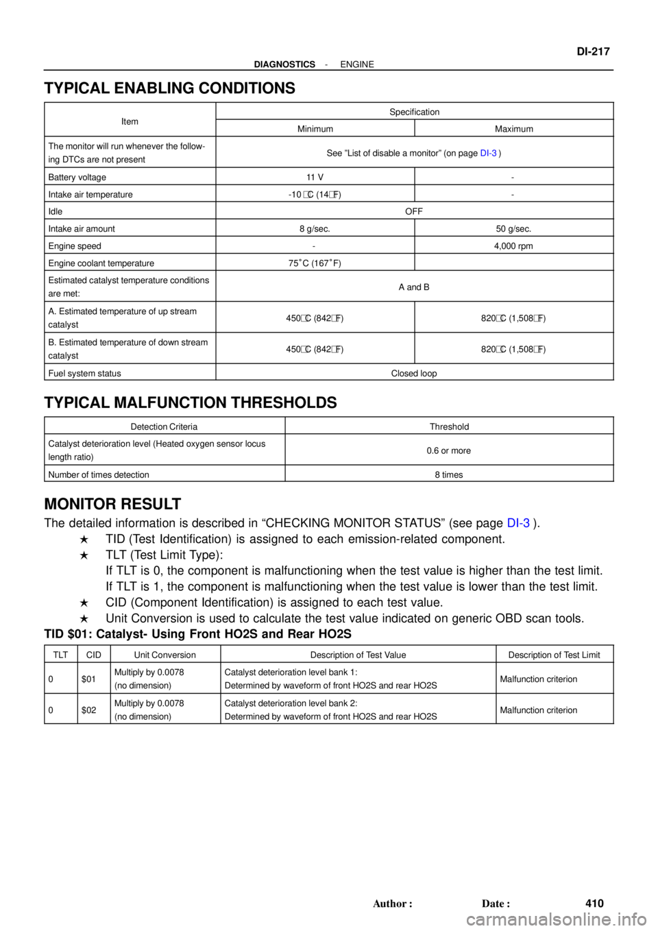
TYPICAL ENABLING CONDITIONS
ItSpecificationItemMinimumMaximum
The monitor will run whenever the follow-
ing DTCs are not presentSee ºList of disable a monitorº (on page DI-3)
Battery voltage11 V-
Intake air temperature-10�C (14�F)-
IdleOFF
Intake air amount8 g/sec.50 g/sec.
Engine speed-4,000 rpm
Engine coolant temperature75°C (167°F)
Estimated catalyst temperature conditions
are met:A and B
A. Estimated temperature of up stream
catalyst450�C (842�F)820�C (1,508�F)
B. Estimated temperature of down stream
catalyst450�C (842�F)820�C (1,508�F)
Fuel system statusClosed loop
TYPICAL MALFUNCTION THRESHOLDS
Detection CriteriaThreshold
Catalyst deterioration level (Heated oxygen sensor locus
length ratio)0.6 or more
Number of times detection8 times
MONITOR RESULT
The detailed information is described in CHECKING MONITOR STATUSº (see page DI-3).
�TID (Test Identification) is assigned to each emission-related component.
�TLT (Test Limit Type):
If TLT is 0, the component is malfunctioning when the test value is higher than the test limit.
If TLT is 1, the component is malfunctioning when the test value is lower than the test limit.
�CID (Component Identification) is assigned to each test value.
�Unit Conversion is used to calculate the test value indicated on generic OBD scan tools.
TID $01: Catalyst- Using Front HO2S and Rear HO2S
TLTCIDUnit ConversionDescription of Test ValueDescription of Test Limit
0$01Multiply by 0.0078
(no dimension)Catalyst deterioration level bank 1:
Determined by waveform of front HO2S and rear HO2SMalfunction criterion
0$02Multiply by 0.0078
(no dimension)Catalyst deterioration level bank 2:
Determined by waveform of front HO2S and rear HO2SMalfunction criterion
Page 1475 of 3115
F03704
ON
TOYOTA
Hand-held
TesterExtend
Contract
F05991
Telescopic Motor
Tilt Motor
Connector Telescopic
Motor
Connector
- DIAGNOSTICSPOWER TILT AND POWER TELESCOPIC STEERING
COLUMNDI-685
878 Author�: Date�:
2004 LAND CRUISER (RM1071U)
INSPECTION PROCEDURE
In case of using TOYOTA hand-held tester, start inspection from step 1.
In case of not using TOYOTA hand-held tester, start inspection from step 2.
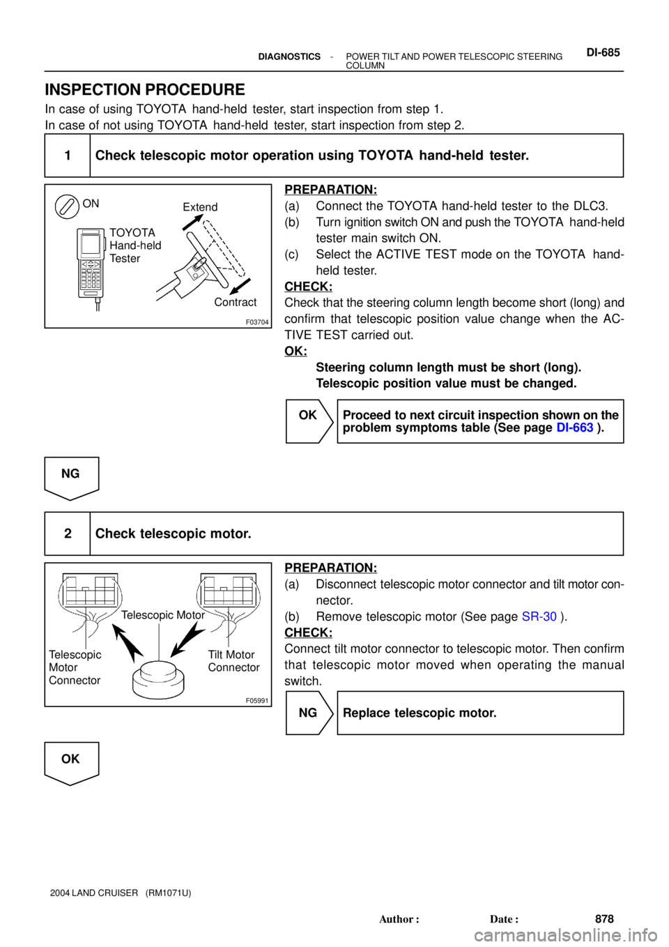
1 Check telescopic motor operation using TOYOTA hand-held tester.
PREPARATION:
(a) Connect the TOYOTA hand-held tester to the DLC3.
(b) Turn ignition switch ON and push the TOYOTA hand-held
tester main switch ON.
(c) Select the ACTIVE TEST mode on the TOYOTA hand-
held tester.
CHECK:
Check that the steering column length become short (long) and
confirm that telescopic position value change when the AC-
TIVE TEST carried out.
OK:
Steering column length must be short (long).
Telescopic position value must be changed.
OK Proceed to next circuit inspection shown on the
problem symptoms table (See page DI-663).
NG
2 Check telescopic motor.
PREPARATION:
(a) Disconnect telescopic motor connector and tilt motor con-
nector.
(b) Remove telescopic motor (See page SR-30).
CHECK:
Connect tilt motor connector to telescopic motor. Then confirm
that telescopic motor moved when operating the manual
switch.
NG Replace telescopic motor.
OK
Page 1835 of 3115

EM0181
Margin Thickness
EM2534
Overall Length
EM0255
EM6330
45° Carbide Cutter EM-48
- ENGINE MECHANICALCYLINDER HEAD
1621 Author�: Date�:
2004 LAND CRUISER (RM1071U)
(c) Check the valve head margin thickness.
Standard margin thickness:
IN 1.25 mm (0.049 in.)
EX 1.40 mm (0.055 in.)
Minimum margin thickness:
0.5 mm (0.020 in.)
If the margin thickness is less than the minimum, replace the
valve.
(d) Check the valve overall length.
Standard overall length:
Intake: 95.05 mm (3.7421 in.)
Exhaust: 95.10 mm (3.7441 in.)
Minimum overall length:
Intake: 94.55 mm (3.7224 in.)
Exhaust: 94.60 mm (3.7244 in.)
If the overall length is less than the minimum, replace the valve.
(e) Check the surface of the valve stem tip for wear.
If the valve stem tip is worn, resurface the tip with a grinder or
replace the valve.
NOTICE:
Do not grind off to below the minimum.
11. INSPECT AND CLEAN VALVE SEATS
(a) Using a 45° carbide cutter, resurface the valve seats. Re-
move just enough metal to clean the seats.
Page 1837 of 3115

EM0801
EM0281
A05912
EM2011
EM-50
- ENGINE MECHANICALCYLINDER HEAD
1623 Author�: Date�:
2004 LAND CRUISER (RM1071U)
(b) Using vernier calipers, measure the free length of the
valve spring.
Free length:
54.1 mm (2.130 in.)
If the free length is not as specified, replace the valve spring.
(c) Using a spring tester, measure the tension of the valve
spring at the installed length.
Installed tension:
204 - 226 N (20.8 - 23.0 kgf, 45.9 - 50.7 lbf)
at 35.0 mm (1.378 in.)
If the installed tension is not as specified, replace the valve
spring.
13. INSPECT CAMSHAFT FOR RUNOUT
(a) Place the camshaft on V-blocks.
(b) Using a dial indicator, measure the circle runout at the
center journal.
Maximum circle runout:
0.08 mm (0.0031 in.)
If the circle runout is greater than the maximum, replace the
camshaft.
14. INSPECT CAM LOBES
Using a micrometer, measure the cam lobe height.
Standard cam lobe height:
Intake:
41.94 - 42.04 mm (1.6512 - 1.6551 in.)
Exhaust:
41.96 - 42.06 mm (1.6520 - 1.6559 in.)
Minimum cam lobe height:
Intake:
41.79 mm (1.6453 in.)
Exhaust:
41.81 mm (1.6461 in.)
If the cam lobe height is less than the minimum, replace the
camshaft.
Page 1847 of 3115
A05504Front
A05505
Push
A04469
A
B
C
C
E
E
D
D
E
E
A04469
10
1
256789
1112 13
141516
1718
19
2022
3
4
21
EM-64
- ENGINE MECHANICALCYLINDER HEAD
1637 Author�: Date�:
2004 LAND CRUISER (RM1071U)
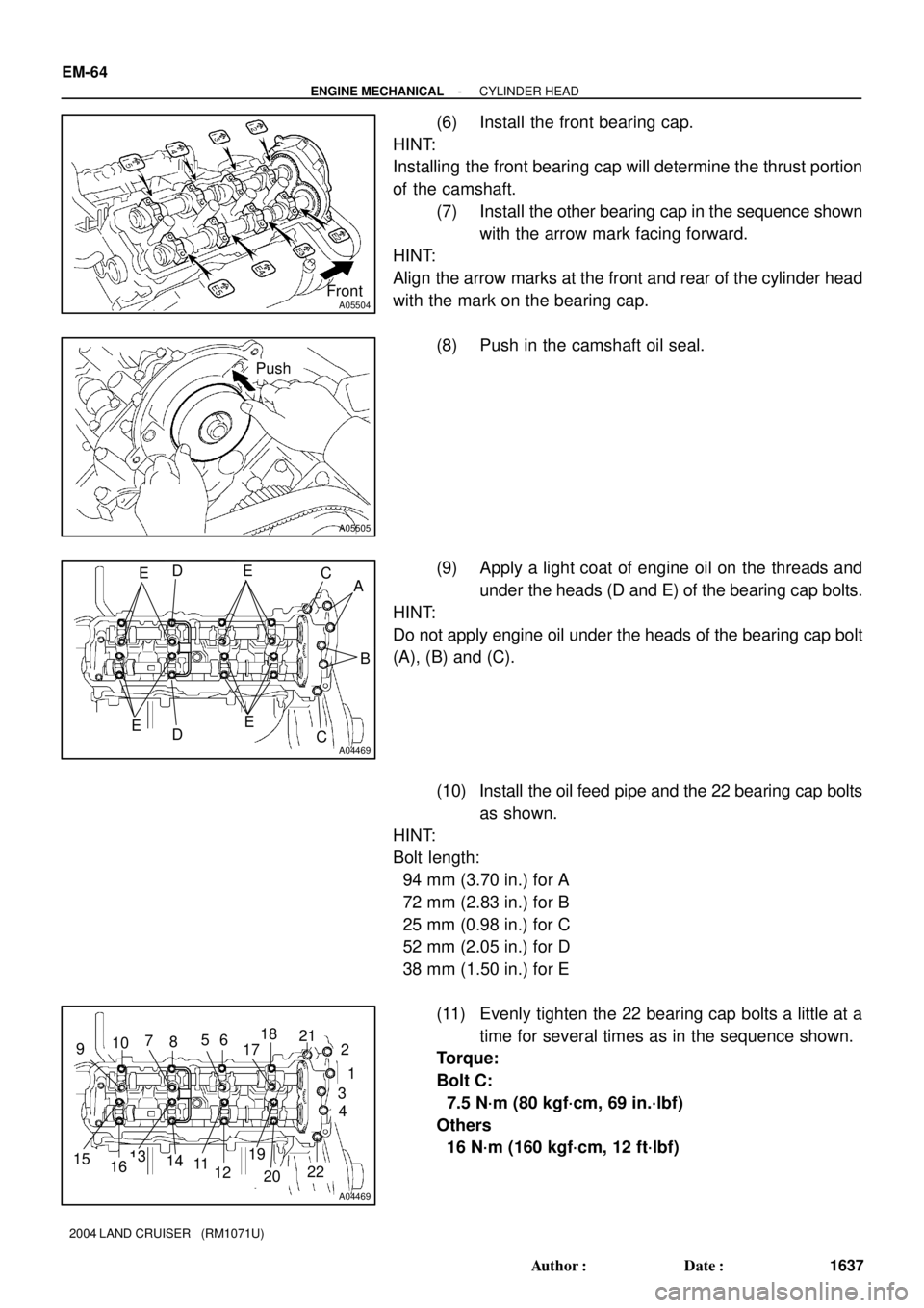
(6) Install the front bearing cap.
HINT:
Installing the front bearing cap will determine the thrust portion
of the camshaft.
(7) Install the other bearing cap in the sequence shown
with the arrow mark facing forward.
HINT:
Align the arrow marks at the front and rear of the cylinder head
with the mark on the bearing cap.
(8) Push in the camshaft oil seal.
(9) Apply a light coat of engine oil on the threads and
under the heads (D and E) of the bearing cap bolts.
HINT:
Do not apply engine oil under the heads of the bearing cap bolt
(A), (B) and (C).
(10) Install the oil feed pipe and the 22 bearing cap bolts
as shown.
HINT:
Bolt length:
94 mm (3.70 in.) for A
72 mm (2.83 in.) for B
25 mm (0.98 in.) for C
52 mm (2.05 in.) for D
38 mm (1.50 in.) for E
(11) Evenly tighten the 22 bearing cap bolts a little at a
time for several times as in the sequence shown.
Torque:
Bolt C:
7.5 N´m (80 kgf´cm, 69 in.´lbf)
Others
16 N´m (160 kgf´cm, 12 ft´lbf)
Page 1849 of 3115
A05507
Push
A04470
E D E
C
A
E D
E C B
A04470
10
1
2
56789
111213
141516
17 18
19
2022
3
4
21
A02856
Service
Bolt
EM-66
- ENGINE MECHANICALCYLINDER HEAD
1639 Author�: Date�:
2004 LAND CRUISER (RM1071U)
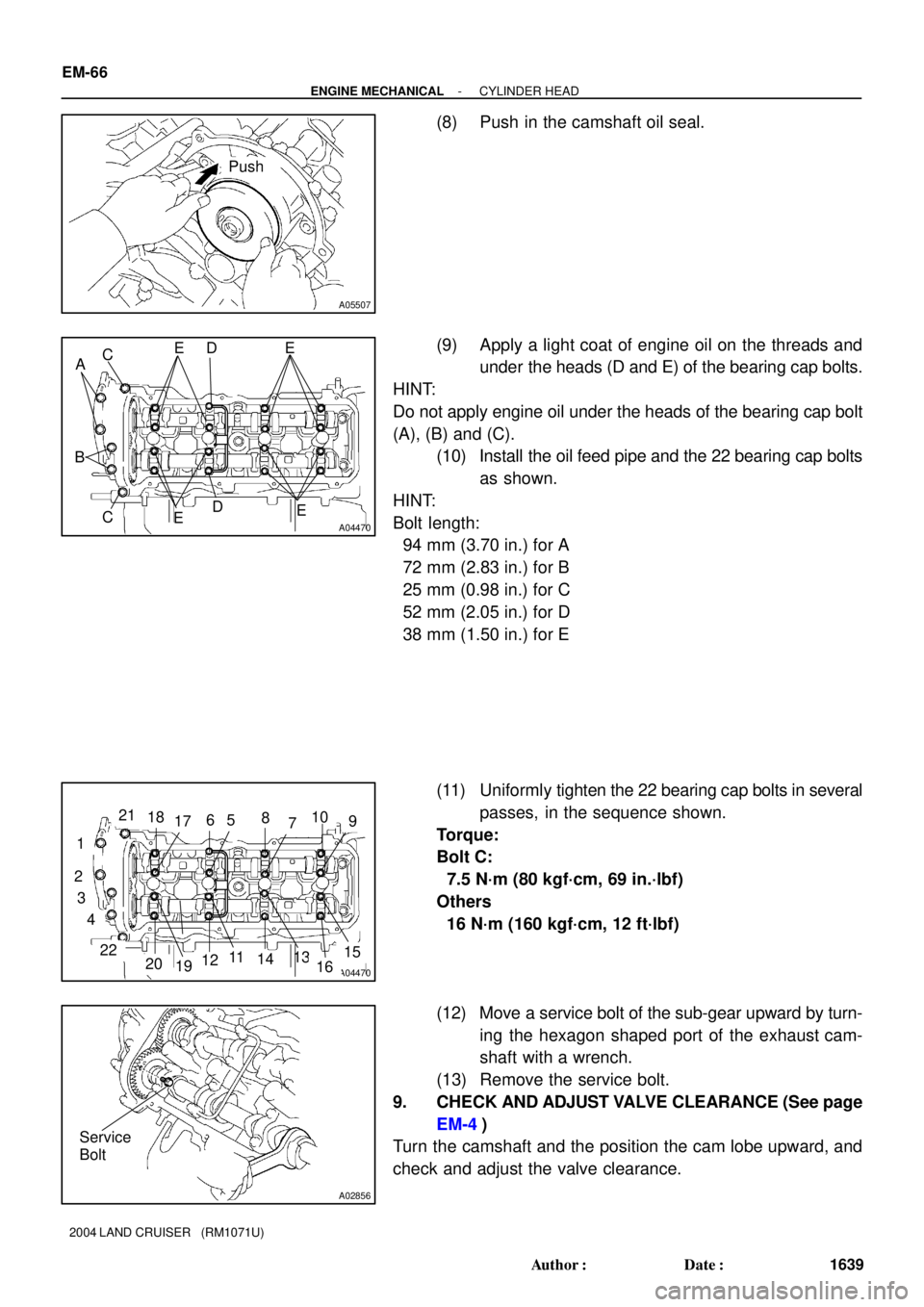
(8) Push in the camshaft oil seal.
(9) Apply a light coat of engine oil on the threads and
under the heads (D and E) of the bearing cap bolts.
HINT:
Do not apply engine oil under the heads of the bearing cap bolt
(A), (B) and (C).
(10) Install the oil feed pipe and the 22 bearing cap bolts
as shown.
HINT:
Bolt length:
94 mm (3.70 in.) for A
72 mm (2.83 in.) for B
25 mm (0.98 in.) for C
52 mm (2.05 in.) for D
38 mm (1.50 in.) for E
(11) Uniformly tighten the 22 bearing cap bolts in several
passes, in the sequence shown.
Torque:
Bolt C:
7.5 N´m (80 kgf´cm, 69 in.´lbf)
Others
16 N´m (160 kgf´cm, 12 ft´lbf)
(12) Move a service bolt of the sub-gear upward by turn-
ing the hexagon shaped port of the exhaust cam-
shaft with a wrench.
(13) Remove the service bolt.
9. CHECK AND ADJUST VALVE CLEARANCE (See page
EM-4)
Turn the camshaft and the position the cam lobe upward, and
check and adjust the valve clearance.
Page 1860 of 3115
A04456
No. 2 Idler
Pulley Bolt
Crankshaft
Pulley BoltTiming
Mark
A04467Service Bolt
A04468
A04469
8101241
14161862
19
2021
22
1315175
79113
- ENGINE MECHANICALCYLINDER HEAD
EM-39
1612 Author�: Date�:
2004 LAND CRUISER (RM1071U)
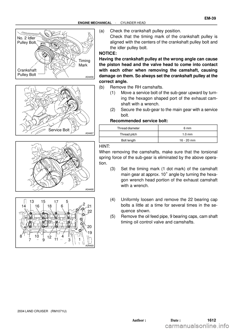
(a) Check the crankshaft pulley position.
Check that the timing mark of the crankshaft pulley is
aligned with the centers of the crankshaft pulley bolt and
the idler pulley bolt.
NOTICE:
Having the crankshaft pulley at the wrong angle can cause
the piston head and the valve head to come into contact
with each other when removing the camshaft, causing
damage on them. So always set the crankshaft pulley at the
correct angle.
(b) Remove the RH camshafts.
(1) Move a service bolt of the sub-gear upward by turn-
ing the hexagon shaped port of the exhaust cam-
shaft with a wrench.
(2) Secure the sub-gear to the main gear with a service
bolt.
Recommended service bolt:
Thread diameter6 mm
Thread pitch1.0 mm
Bolt length16 - 20 mm
HINT:
When removing the camshafts, make sure that the torsional
spring force of the sub-gear is eliminated by the above opera-
tion.
(3) Set the timing mark (1 dot mark) of the camshaft
main gear at approx. 10° angle by turning the hexa-
gon wrench head portion of the exhaust camshaft
with a wrench.
(4) Uniformly loosen and remove the 22 bearing cap
bolts a little at a time for several times in the se-
quence shown.
(5) Remove the oil feed pipe, 9 bearing caps, cam shaft
timing oil control valve and camshafts.
Page 1861 of 3115
A02856Service Bolt
A02857
Align
A04470
4
6
108
1
16
12
18 2
19 20 2221
15
3
5
97
14
1713
11
A02859
A02850
SST
Service Bolt
Turn EM-40
- ENGINE MECHANICALCYLINDER HEAD
1613 Author�: Date�:
2004 LAND CRUISER (RM1071U)
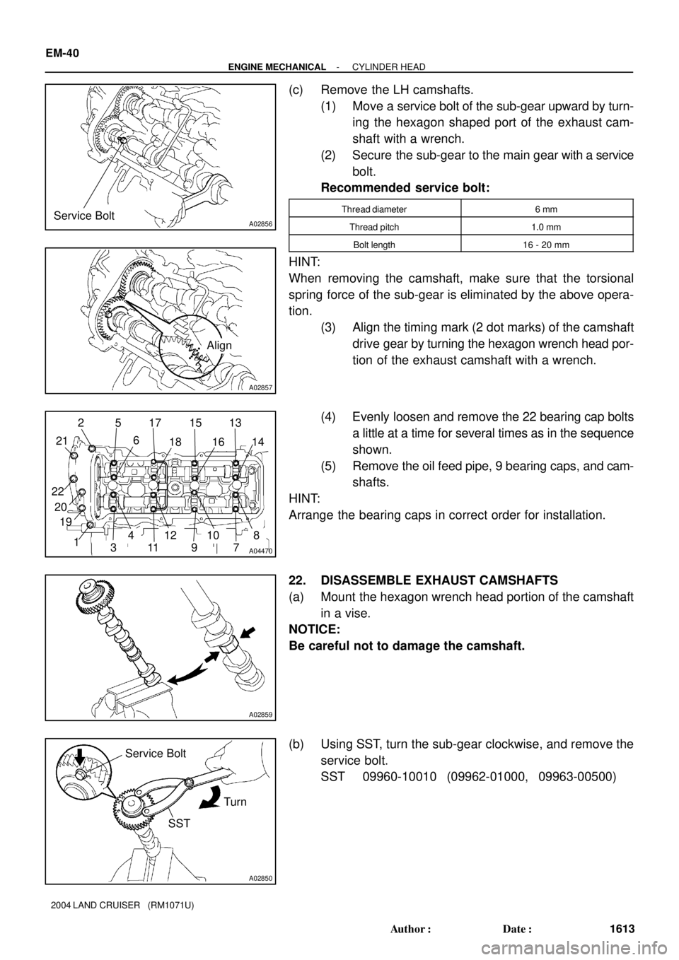
(c) Remove the LH camshafts.
(1) Move a service bolt of the sub-gear upward by turn-
ing the hexagon shaped port of the exhaust cam-
shaft with a wrench.
(2) Secure the sub-gear to the main gear with a service
bolt.
Recommended service bolt:
Thread diameter6 mm
Thread pitch1.0 mm
Bolt length16 - 20 mm
HINT:
When removing the camshaft, make sure that the torsional
spring force of the sub-gear is eliminated by the above opera-
tion.
(3) Align the timing mark (2 dot marks) of the camshaft
drive gear by turning the hexagon wrench head por-
tion of the exhaust camshaft with a wrench.
(4) Evenly loosen and remove the 22 bearing cap bolts
a little at a time for several times as in the sequence
shown.
(5) Remove the oil feed pipe, 9 bearing caps, and cam-
shafts.
HINT:
Arrange the bearing caps in correct order for installation.
22. DISASSEMBLE EXHAUST CAMSHAFTS
(a) Mount the hexagon wrench head portion of the camshaft
in a vise.
NOTICE:
Be careful not to damage the camshaft.
(b) Using SST, turn the sub-gear clockwise, and remove the
service bolt.
SST 09960-10010 (09962-01000, 09963-00500)