Page 2884 of 3115

SA16A-02
F04391
F04392
F04393
F04394
SA-172
- SUSPENSION AND AXLECOIL SPRING AND REAR SHOCK ABSORBER
2122 Author�: Date�:
2004 LAND CRUISER (RM1071U)
REMOVAL
1. REMOVE REAR WHEELS
Torque: 131 N´m (1,340 kgf´cm, 97 ft´lbf)
2. SUPPORT REAR AXLE HOUSING WITH JACK
3. REMOVE SHOCK ABSORBER
(a) Remove the bolt and disconnect the shock absorber from
the axle housing.
Torque: 98 N´m (1,000 kgf´cm, 72 ft´lbf)
(b) Employ the same manner described above to the other
side.
(c) While holding the piston rod, remove the nut, 2 retainers,
cushion and shock absorber.
Torque: 69 N´m (704 kgf´cm, 51 ft´lbf)
(d) Remove the 2 retainers and cushion from the shock ab-
sorber.
4. DISCONNECT LH AND RH STABILIZER BAR BRACK-
ETS
Remove the 4 bolts and disconnect the LH and RH stabilizer bar
brackets.
Torque: 18 N´m (185 kgf´cm, 13 ft´lbf)
5. DISCONNECT LATERAL CONTROL ROD
Remove the nut, washer, bolt and disconnect the lateral control
rod.
Torque: 150 N´m (1,530 kgf´cm, 111 ft´lbf)
HINT:
At the time of installation, after stabilizing the suspension,
torque the nut and bolt.
6. DISCONNECT BREATHER HOSE
Page 2898 of 3115

F04362
90°
F04363
- SUSPENSION AND AXLEFRONT AXLE HUB
SA-17
1967 Author�: Date�:
2004 LAND CRUISER (RM1071U)
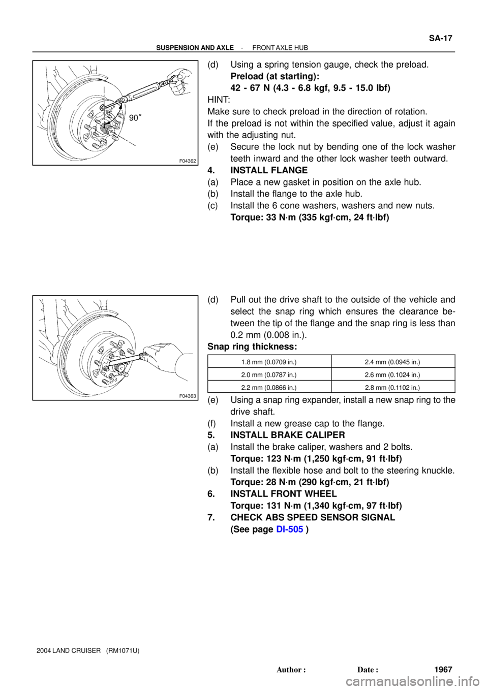
(d) Using a spring tension gauge, check the preload.
Preload (at starting):
42 - 67 N (4.3 - 6.8 kgf, 9.5 - 15.0 lbf)
HINT:
Make sure to check preload in the direction of rotation.
If the preload is not within the specified value, adjust it again
with the adjusting nut.
(e) Secure the lock nut by bending one of the lock washer
teeth inward and the other lock washer teeth outward.
4. INSTALL FLANGE
(a) Place a new gasket in position on the axle hub.
(b) Install the flange to the axle hub.
(c) Install the 6 cone washers, washers and new nuts.
Torque: 33 N´m (335 kgf´cm, 24 ft´lbf)
(d) Pull out the drive shaft to the outside of the vehicle and
select the snap ring which ensures the clearance be-
tween the tip of the flange and the snap ring is less than
0.2 mm (0.008 in.).
Snap ring thickness:
1.8 mm (0.0709 in.)2.4 mm (0.0945 in.)
2.0 mm (0.0787 in.)2.6 mm (0.1024 in.)
2.2 mm (0.0866 in.)2.8 mm (0.1102 in.)
(e) Using a snap ring expander, install a new snap ring to the
drive shaft.
(f) Install a new grease cap to the flange.
5. INSTALL BRAKE CALIPER
(a) Install the brake caliper, washers and 2 bolts.
Torque: 123 N´m (1,250 kgf´cm, 91 ft´lbf)
(b) Install the flexible hose and bolt to the steering knuckle.
Torque: 28 N´m (290 kgf´cm, 21 ft´lbf)
6. INSTALL FRONT WHEEL
Torque: 131 N´m (1,340 kgf´cm, 97 ft´lbf)
7. CHECK ABS SPEED SENSOR SIGNAL
(See page DI-505)
Page 2924 of 3115

SA14M-04
F04403
Matchmarks
F05232
ABB
BB
F04404
A
A
BB
AA
- SUSPENSION AND AXLEFRONT DIFFERENTIAL CARRIER
SA-39
1989 Author�: Date�:
2004 LAND CRUISER (RM1071U)
REMOVAL
1. REMOVE FRONT WHEELS
Torque: 131 N´m (1,340 kgf´cm, 97 ft´lbf)
2. REMOVE DRIVE SHAFTS (See page SA-26)
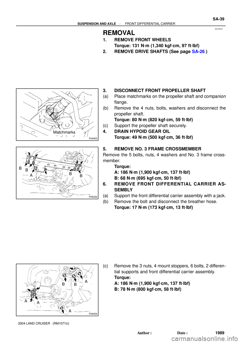
3. DISCONNECT FRONT PROPELLER SHAFT
(a) Place matchmarks on the propeller shaft and companion
flange.
(b) Remove the 4 nuts, bolts, washers and disconnect the
propeller shaft.
Torque: 80 N´m (820 kgf´cm, 59 ft´lbf)
(c) Support the propeller shaft securely.
4. DRAIN HYPOID GEAR OIL
Torque: 49 N´m (500 kgf´cm, 36 ft´lbf)
5. REMOVE NO. 3 FRAME CROSSMEMBER
Remove the 5 bolts, nuts, 4 washers and No. 3 frame cross-
member.
Torque:
A: 186 N´m (1,900 kgf´cm, 137 ft´lbf)
B: 68 N´m (695 kgf´cm, 50 ft´lbf)
6. REMOVE FRONT DIFFERENTIAL CARRIER AS-
SEMBLY
(a) Support the front differential carrier assembly with a jack.
(b) Remove the bolt and disconnect the breather hose.
Torque: 17 N´m (173 kgf´cm, 13 ft´lbf)
(c) Remove the 3 nuts, 4 mount stoppers, 6 bolts, 2 differen-
tial supports and front differential carrier assembly.
Torque:
A: 186 N´m (1,900 kgf´cm, 137 ft´lbf)
B: 78 N´m (800 kgf´cm, 58 ft´lbf)
Page 2932 of 3115

SA14F-04
F04367
F04368
F05795
A
B
C
F05161
SA-26
- SUSPENSION AND AXLEFRONT DRIVE SHAFT
1976 Author�: Date�:
2004 LAND CRUISER (RM1071U)
REMOVAL
1. REMOVE FRONT WHEEL
Torque: 131 N´m (1,340 kgf´cm, 97 ft´lbf)
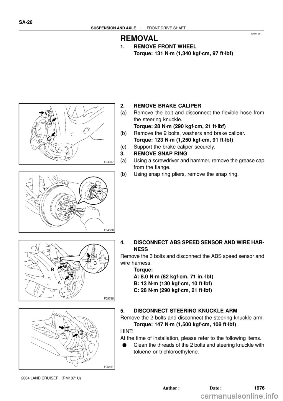
2. REMOVE BRAKE CALIPER
(a) Remove the bolt and disconnect the flexible hose from
the steering knuckle.
Torque: 28 N´m (290 kgf´cm, 21 ft´lbf)
(b) Remove the 2 bolts, washers and brake caliper.
Torque: 123 N´m (1,250 kgf´cm, 91 ft´lbf)
(c) Support the brake caliper securely.
3. REMOVE SNAP RING
(a) Using a screwdriver and hammer, remove the grease cap
from the flange.
(b) Using snap ring pliers, remove the snap ring.
4. DISCONNECT ABS SPEED SENSOR AND WIRE HAR-
NESS
Remove the 3 bolts and disconnect the ABS speed sensor and
wire harness.
Torque:
A: 8.0 N´m (82 kgf´cm, 71 in.´lbf)
B: 13 N´m (130 kgf´cm, 10 ft´lbf)
C: 28 N´m (290 kgf´cm, 21 ft´lbf)
5. DISCONNECT STEERING KNUCKLE ARM
Remove the 2 bolts and disconnect the steering knuckle arm.
Torque: 147 N´m (1,500 kgf´cm, 108 ft´lbf)
HINT:
At the time of installation, please refer to the following items.
�Clean the threads of the 2 bolts and steering knuckle with
toluene or trichloroethylene.
Page 2936 of 3115
SA14K-04
F05234
SST
F05235
SST
F05233
Less than 5 mm (0.20 in.)
- SUSPENSION AND AXLEFRONT DIFFERENTIAL SIDE GEAR SHAFT OIL SEAL
SA-35
1985 Author�: Date�:
2004 LAND CRUISER (RM1071U)
REPLACEMENT
1. REMOVE FRONT WHEELS
Torque: 131 N´m (1,340 kgf´cm, 97 ft´lbf)
2. REMOVE FRONT DRIVE SHAFT
(See page SA-26)
3. REPLACE OIL SEAL
(a) Using SST, remove the oil seal.
SST 09308-00010
(b) Coat the hypoid gear oil to a new oil seal periphery.
(c) Using SST and a hammer, install the new oil seal.
SST 09550-00032, 09950-70010 (09951-07100)
(d) Coat the MP grease to the oil seal lip.
4. INSTALL FRONT DRIVE SHAFT
(See page SA-33)
5. FILL DIFFERENTIAL WITH HYPOID GEAR OIL
Torque: 49 N´m (500 kgf´cm, 36 ft´lbf)
Oil type: Hypoid gear oil API GL-5
Recommended oil viscosity:
Above -18°C (0°F) SAE 90
Below -18°C (0°F) SAE 80W-90 or 80W
Capacity: 1.70 liters (1.80 US qts, 1.50 lmp.qts)
Page 2940 of 3115

SA155-02
F04381
F04382
F04383
SST
F04384
- SUSPENSION AND AXLEFRONT LOWER SUSPENSION ARM
SA-75
2025 Author�: Date�:
2004 LAND CRUISER (RM1071U)
REMOVAL
1. REMOVE FRONT WHEEL
Torque: 131 N´m (1,340 kgf´cm, 97 ft´lbf)
2. REMOVE ENGINE UNDER COVER
3. REMOVE FRONT TORSION BAR SPRING
(See page SA-66)
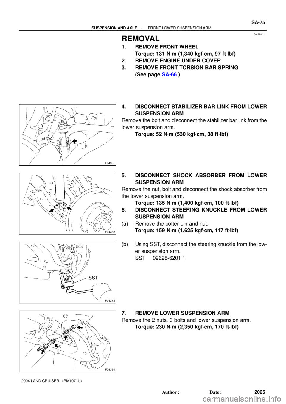
4. DISCONNECT STABILIZER BAR LINK FROM LOWER
SUSPENSION ARM
Remove the bolt and disconnect the stabilizer bar link from the
lower suspension arm.
Torque: 52 N´m (530 kgf´cm, 38 ft´lbf)
5. DISCONNECT SHOCK ABSORBER FROM LOWER
SUSPENSION ARM
Remove the nut, bolt and disconnect the shock absorber from
the lower suspension arm.
Torque: 135 N´m (1,400 kgf´cm, 100 ft´lbf)
6. DISCONNECT STEERING KNUCKLE FROM LOWER
SUSPENSION ARM
(a) Remove the cotter pin and nut.
Torque: 159 N´m (1,625 kgf´cm, 117 ft´lbf)
(b) Using SST, disconnect the steering knuckle from the low-
er suspension arm.
SST 09628-6201 1
7. REMOVE LOWER SUSPENSION ARM
Remove the 2 nuts, 3 bolts and lower suspension arm.
Torque: 230 N´m (2,350 kgf´cm, 170 ft´lbf)
Page 2947 of 3115
SA14S-02
F04382
F04407
- SUSPENSION AND AXLEFRONT SHOCK ABSORBER
SA-61
2011 Author�: Date�:
2004 LAND CRUISER (RM1071U)
REMOVAL
1. REMOVE FRONT WHEEL
Torque: 131 N´m (1,340 kgf´cm, 97 ft´lbf)
2. REMOVE FRONT FENDER APRON
3. REMOVE SHOCK ABSORBER
(a) Remove the bolt, nut and disconnect the shock absorber
from the lower suspension arm.
Torque: 135 N´m (1,400 kgf´cm, 100 ft´lbf)
(b) While holding the piston rod, remove the nut, cushion, re-
tainer and shock absorber.
Torque: 68 N´m (700 kgf´cm, 50 ft´lbf)
(c) Remove the cushion and retainer from the shock absorb-
er.
Page 2953 of 3115
F05246
A SA-68
- SUSPENSION AND AXLEFRONT TORSION BAR SPRING
2018 Author�: Date�:
2004 LAND CRUISER (RM1071U)
(1) Align matchmarks on the torsion bar spring and an-
chor arm and install them.
(2) Align matchmarks on the torsion bar spring and
torque arm and install them.
(3) Tighten the anchor arm bolt adjusting so that the di-
mension ºAº is almost same as the dimension mea-
sured when the torsion bar spring was removed.
3. INSTALL ENGINE UNDER COVER
4. INSTALL FRONT WHEEL
Torque: 131 N´m (1,340 kgf´cm, 97 ft´lbf)
5. CHECK VEHICLE HEIGHT (See page SA-6)
HINT:
After stabilizing the suspension, adjust the vehicle height by
turning the anchor arm bolt.