Page 2954 of 3115
SA14X-02
F05247
Matchmarks
F05246
A
F05245
B SA-66
- SUSPENSION AND AXLEFRONT TORSION BAR SPRING
2016 Author�: Date�:
2004 LAND CRUISER (RM1071U)
REMOVAL
1. REMOVE FRONT WHEEL
2. REMOVE ENGINE UNDER COVER
3. REMOVE TORSION BAR SPRING WITH ANCHOR
ARM
(a) Place matchmarks on the torsion bar spring, anchor arm
and torque arm.
(b) Measure the dimension ºAº between the anchor arm ad-
justing bolt end and the frame as shown.
HINT:
Use the measurement for a reference when installing the an-
chor arm.
(c) Loosen the anchor arm bolt until the spring tension is free
and measure the anchor arm bolt ºBº.
HINT:
Use the measurement for a reference when installing the an-
chor arm.
(d) Remove the anchor arm adjusting bolt, anchor arm swivel
and anchor arm adjusting seat.
(e) Remove the torsion bar spring with the anchor arm.
(f) Remove the anchor arm from the torsion bar spring.
4. REMOVE TORQUE ARM
Remove the 2 nuts, bolt and torque arm.
Page 2958 of 3115

SA150-02
F04377
F04378
SST
F04379
Matchmarks
SA-70
- SUSPENSION AND AXLEFRONT UPPER SUSPENSION ARM
2020 Author�: Date�:
2004 LAND CRUISER (RM1071U)
REMOVAL
1. REMOVE FRONT WHEEL
Torque: 131 N´m (1,340 kgf´cm, 97 ft´lbf)
2. REMOVE FRONT FENDER APRON
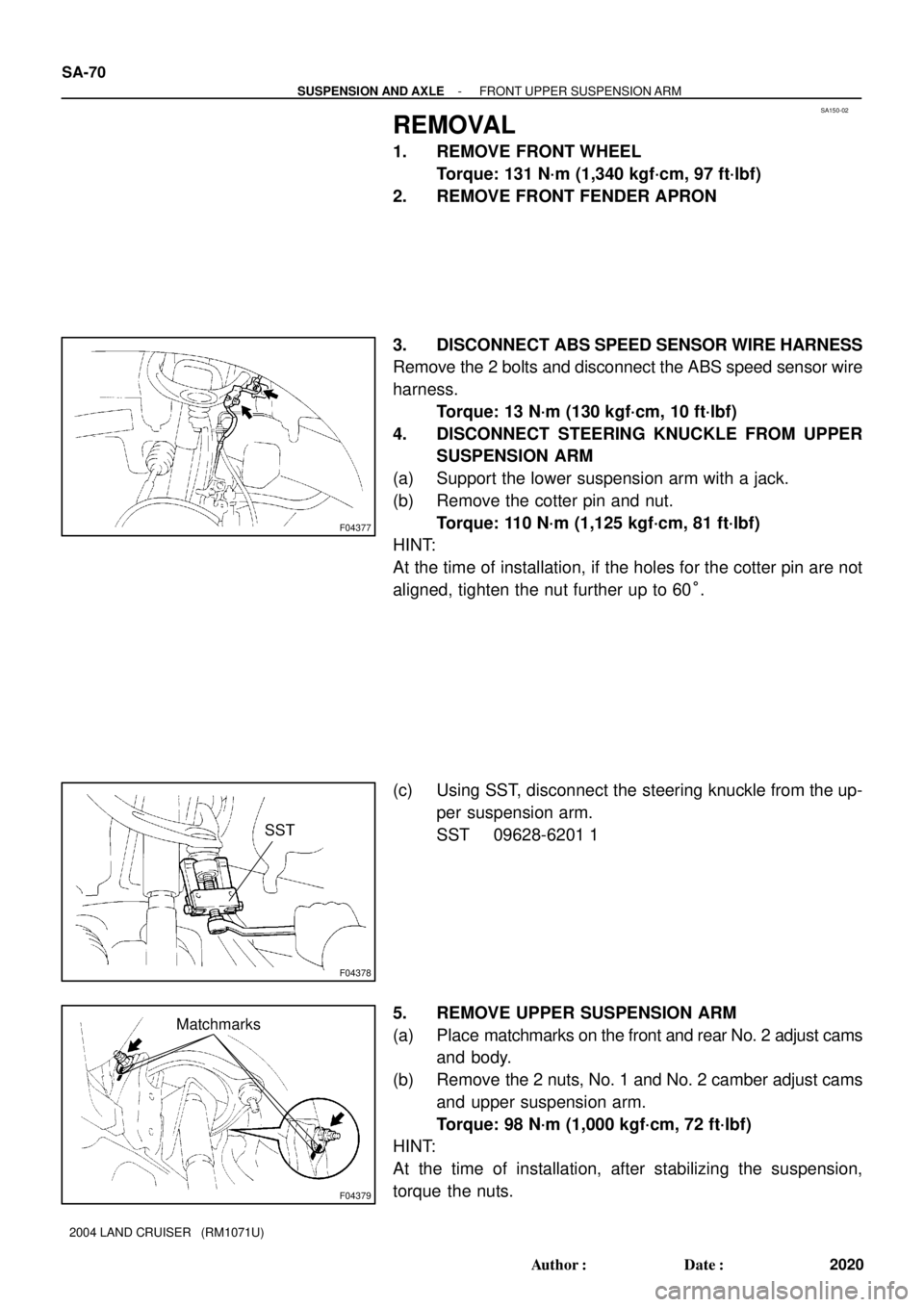
3. DISCONNECT ABS SPEED SENSOR WIRE HARNESS
Remove the 2 bolts and disconnect the ABS speed sensor wire
harness.
Torque: 13 N´m (130 kgf´cm, 10 ft´lbf)
4. DISCONNECT STEERING KNUCKLE FROM UPPER
SUSPENSION ARM
(a) Support the lower suspension arm with a jack.
(b) Remove the cotter pin and nut.
Torque: 110 N´m (1,125 kgf´cm, 81 ft´lbf)
HINT:
At the time of installation, if the holes for the cotter pin are not
aligned, tighten the nut further up to 60°.
(c) Using SST, disconnect the steering knuckle from the up-
per suspension arm.
SST 09628-6201 1
5. REMOVE UPPER SUSPENSION ARM
(a) Place matchmarks on the front and rear No. 2 adjust cams
and body.
(b) Remove the 2 nuts, No. 1 and No. 2 camber adjust cams
and upper suspension arm.
Torque: 98 N´m (1,000 kgf´cm, 72 ft´lbf)
HINT:
At the time of installation, after stabilizing the suspension,
torque the nuts.
Page 2963 of 3115

SA3213
AB
CD
Front
F05208
- SUSPENSION AND AXLEFRONT WHEEL ALIGNMENT
SA-9
1959 Author�: Date�:
2004 LAND CRUISER (RM1071U)
(d) Torque the front and/or rear adjusting cam nuts.
Torque: 98 N´m (1,000 kgf´cm, 72 ft´lbf)
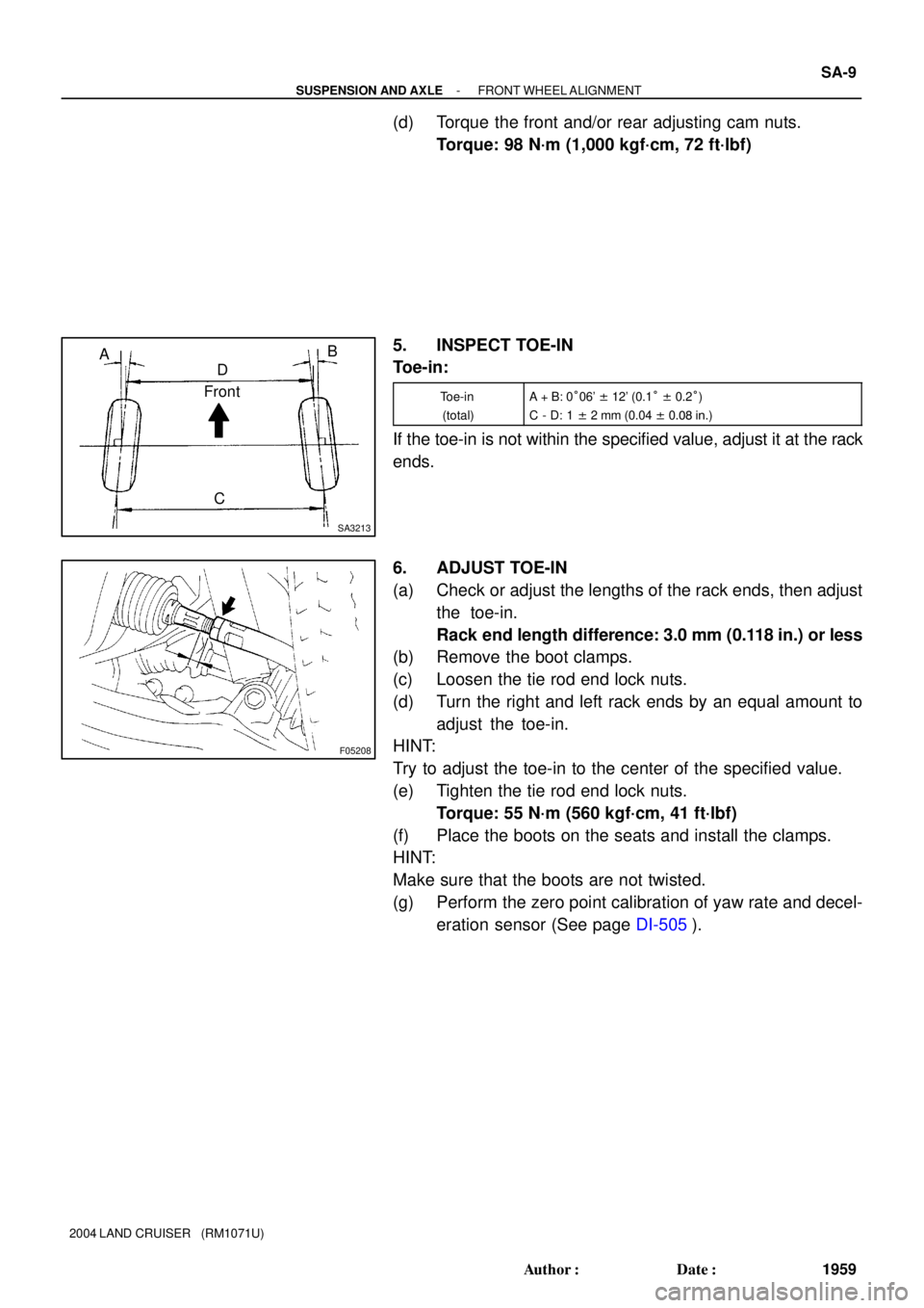
5. INSPECT TOE-IN
Toe-in:
Toe-in
(total)A + B: 0°06' ± 12' (0.1° ± 0.2°)
C - D: 1 ± 2 mm (0.04 ± 0.08 in.)
If the toe-in is not within the specified value, adjust it at the rack
ends.
6. ADJUST TOE-IN
(a) Check or adjust the lengths of the rack ends, then adjust
the toe-in.
Rack end length difference: 3.0 mm (0.118 in.) or less
(b) Remove the boot clamps.
(c) Loosen the tie rod end lock nuts.
(d) Turn the right and left rack ends by an equal amount to
adjust the toe-in.
HINT:
Try to adjust the toe-in to the center of the specified value.
(e) Tighten the tie rod end lock nuts.
Torque: 55 N´m (560 kgf´cm, 41 ft´lbf)
(f) Place the boots on the seats and install the clamps.
HINT:
Make sure that the boots are not twisted.
(g) Perform the zero point calibration of yaw rate and decel-
eration sensor (See page DI-505).
Page 2964 of 3115
SA0028
AB
FrontBA
A: Inside
B: Outside
F05200
SA-10
- SUSPENSION AND AXLEFRONT WHEEL ALIGNMENT
1960 Author�: Date�:
2004 LAND CRUISER (RM1071U)
7. INSPECT AND ADJUST WHEEL ANGLE
(a) Turn the steering wheel fully, and measure the turning
angle.
Wheel turning angle:
Inside wheel36°42' (33°42' - 36°42')
36.7° (33.7° - 36.7°)
Outside wheel: Reference32°36'
32.6°
If the right and left inside wheel angles differ from the specified
value, check the right and left rack end lengths.
(b) When toe-in is normal after inspection, adjust wheel
angle with the knuckle stopper bolt of the lower suspen-
sion arm.
Torque: 44 N´m (450 kgf´cm, 32 ft´lbf)
Page 2965 of 3115
SA148-04
F04340Matchmarks
F04344
F04345
F04340Matchmarks
SA-18
- SUSPENSION AND AXLEFRONT WHEEL HUB BOLT
1968 Author�: Date�:
2004 LAND CRUISER (RM1071U)
FRONT WHEEL HUB BOLT
REPLACEMENT
1. REMOVE FRONT AXLE HUB (See page SA-12)
2. REMOVE HUB BOLT
(a) Mount the axle hub with the disc in a soft jaw vice.
NOTICE:
Close vice until it holds disc, do not tighten further.
(b) Place matchmarks on the axle hub and disc.
(c) Remove the 5 bolts and separate the axle hub from the
disc.
(d) Using a press, remove the hub bolt.
3. INSTALL HUB BOLT
(a) Using an extension bar and press, install a new hub bolt.
(b) Align the matchmarks on the axle hub and disc.
(c) Install the 5 bolts to the axle hub.
Torque: 74 N´m (750 kgf´cm, 55 ft´lbf)
4. INSTALL FRONT AXLE HUB (See page SA-16)
Page 2973 of 3115
SA15D-02
F04386
SST
F04387
F04388
SA-84
- SUSPENSION AND AXLEREAR AXLE SHAFT
2034 Author�: Date�:
2004 LAND CRUISER (RM1071U)
REMOVAL
1. REMOVE REAR WHEEL
Torque: 131 N´m (1,340 kgf´cm, 97 ft´lbf)
2. DISCONNECT BRAKE LINE
Using SST, disconnect the brake line and remove the clip.
SST 09023-00100
Torque: 15 N´m (150 kgf´cm, 11 ft´lbf)
3. REMOVE BRAKE CALIPER AND DISC
Remove the 2 bolts, washers, brake caliper and disc.
Torque: 103 N´m (1,050 kgf´cm, 76 ft´lbf)
4. CHECK BEARING BACKLASH AND AXLE SHAFT
DEVIATION
(a) Using a dial indicator, check the backlash in the bearing
shaft direction.
Maximum: 0.6 mm (0.024 in.)
If the backlash exceeds the maximum, replace the bearing.
(b) Using a dial indicator, check the deviation at the surface
of the axle shaft outside the hub bolt.
Maximum: 0.05 mm (0.0020 in.)
If the deviation exceeds the maximum, replace the axle shaft.
5. REMOVE PARKING BRAKE ASSEMBLY
(See page BR-33)
Page 2992 of 3115

SA15N-04
F04386
SST
F05217
F05080
Matchmarks
SA-100
- SUSPENSION AND AXLEREAR DIFFERENTIAL CARRIER
2050 Author�: Date�:
2004 LAND CRUISER (RM1071U)
REMOVAL
1. REMOVE 2 REAR WHEELS
Torque: 131 N´m (1,340 kgf´cm, 97 ft´lbf)
2. DRAIN HYPOID GEAR OIL
Torque: 49 N´m (500 kgf´cm, 36 ft´lbf)
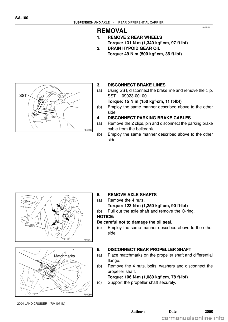
3. DISCONNECT BRAKE LINES
(a) Using SST, disconnect the brake line and remove the clip.
SST 09023-00100
Torque: 15 N´m (150 kgf´cm, 11 ft´lbf)
(b) Employ the same manner described above to the other
side.
4. DISCONNECT PARKING BRAKE CABLES
(a) Remove the 2 clips, pin and disconnect the parking brake
cable from the bellcrank.
(b) Employ the same manner described above to the other
side.
5. REMOVE AXLE SHAFTS
(a) Remove the 4 nuts.
Torque: 123 N´m (1,250 kgf´cm, 90 ft´lbf)
(b) Pull out the axle shaft and remove the O-ring.
NOTICE:
Be careful not to damage the oil seal.
(c) Employ the same manner described above to the other
side.
6. DISCONNECT REAR PROPELLER SHAFT
(a) Place matchmarks on the propeller shaft and differential
flange.
(b) Remove the 4 nuts, bolts, washers and disconnect the
propeller shaft.
Torque: 106 N´m (1,080 kgf´cm, 78 ft´lbf)
(c) Support the propeller shaft securely.
Page 3014 of 3115

SA15T-04
F05181
F04386
SST
- SUSPENSION AND AXLEREAR DIFFERENTIAL CARRIER (w/ Diff. Lock)
SA-1 19
2069 Author�: Date�:
2004 LAND CRUISER (RM1071U)
REMOVAL
1. SHIFTING REAR DIFF. LOCK
(a) Turn the ignition switch to the ON position.
(b) Shift the transfer shift lever to L position.
(c) Turn the differential lock control switch to the RR position
and lock the rear differential.
HINT:
While rotating the tires, check they are in the differential lock
condition.
(d) Disconnect the cable from the negative terminal of the
battery.
2. REMOVE 2 REAR WHEELS
Torque: 131 N´m (1,340 kgf´cm, 97 ft´lbf)
3. DRAIN HYPOID GEAR OIL
Torque: 49 N´m (500 kgf´cm, 36 ft´lbf)
4. DISCONNECT BRAKE LINES
(a) Using SST, disconnect the brake line and remove the clip.
SST 09023-00100
Torque: 15 N´m (150 kgf´cm, 11 ft´lbf)
(b) Employ the same manner described above to the other
side.
5. DISCONNECT PARKING BRAKE CABLES
(a) Remove the 2 clips, pin and disconnect the parking brake
cable from the bellcrank.
(b) Employ the same manner described above to the other
side.