Page 255 of 3115

BE0FZ-19
I24653
I24654
6
I04197
BE-198
- BODY ELECTRICALHORN SYSTEM
2571 Author�: Date�:
2004 LAND CRUISER (RM1071U)
INSPECTION
1. INSPECT HORN SWITCH
(a) Disconnect the negative (-) terminal from the battery.
(b) Remove the left and right covers from the steering wheel.
(c) Using a torx socket wrench, loosen the 2 bolts.
(d) Pull up the horn pad and place it on the steering column,
as shown.
HINT:
Do not disconnect the connector from the horn pad.
(e) Disconnect the connector from the slip ring.
(f) Check that no continuity exists between terminal 6 of the
connector and body ground.
(g) Check that continuity exists between terminal 6 of the
connector and body ground when the horn contact plate
is pressed against the steering spoke assembly.
If continuity is not as specified, repair or replace the steering
wheel or wire harness as necessary.
(h) Install the horn pad in place and using a torx socket
wrench, torque the 2 bolts.
Torque:
7.1 N´m (72 kgf´cm, 62 in.´lbf)
(i) Install the left and right covers.
(j) Connect the negative (-) terminal to the battery.
2. INSPECT HORN OPERATION
Connect the positive (+) lead from the battery to the terminal
and negative (-) lead to the horn body and check that the horn
blows.
If operation is not as specified, replace the horn.
Page 412 of 3115

BO1KK-04
H18910
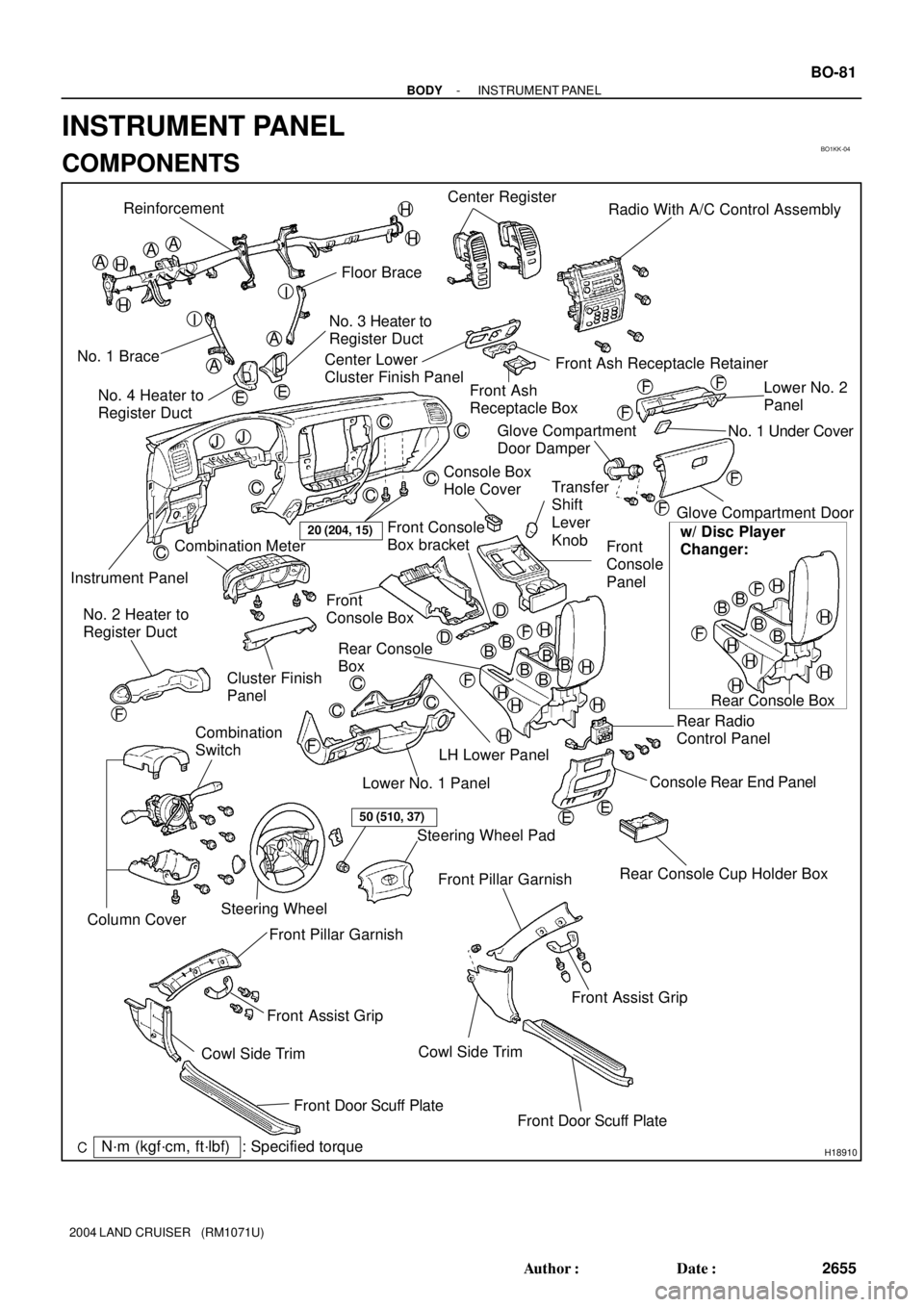
Reinforcement
Floor Brace
No. 1 BraceNo. 3 Heater to
Register Duct
Instrument PanelCenter Register
Radio With A/C Control Assembly
Front Ash Receptacle Retainer Center Lower
Cluster Finish Panel
Front Ash
Receptacle BoxLower No. 2
Panel
Glove Compartment Door
Rear Console Cup Holder Box Front
Console
Panel
Front
Console Box
Rear Console
Box
Rear Radio
Control Panel
Console Rear End Panel Combination Meter
Cluster Finish
Panel
LH Lower Panel
Lower No. 1 Panel No. 2 Heater to
Register Duct
Combination
Switch
Steering WheelSteering Wheel Pad
Front Pillar Garnish
Cowl Side Trim
Front Door Scuff Plate Front Assist Grip No. 4 Heater to
Register Duct
Front Pillar Garnish
Front Assist Grip
Cowl Side Trim
Front Door Scuff Plate
AA
A
A
BBB
C
C
C
C
CC
C
C
C
D
H
A
F
20 (204, 15)
EE
Glove Compartment
Door Damper
50 (510, 37)
BB
Rear Console BoxNo. 1 Under Cover
Console Box
Hole Cover
w/ Disc Player
Changer:
B
Column Cover
Transfer
Shift
Lever
Knob
: Specified torqueN´m (kgf´cm, ft´lbf)
H
H
H
H
I
I
EE
JJ
F
F
F
F
F
H
HH
H
H
BB
BB
HH
H
H
H
H
F
F
F
FF
D Front Console
Box bracket
- BODYINSTRUMENT PANEL
BO-81
2655 Author�: Date�:
2004 LAND CRUISER (RM1071U)
INSTRUMENT PANEL
COMPONENTS
Page 439 of 3115
BO1J7-03
Spare Wheel
Carrier No.1 Lid
H18902
: Specified torqueN´m (kgf´cm, ft´lbf)
Rear Bumper Step Reinforcement
Extension
Mounting
Bracket
Rear Bumper CoverExtension Mounting Bracket
Reflex Reflector
4.9 (50, 43 in.´lbf)
19 (195, 14)
4.9 (50, 43 in.´lbf)
20 (204, 15)
20 (204, 15)
20 (204, 15)
Reflex Reflector
19 (195, 14)
Rear Bumper Lower Cover
12.5 (127, 11)
12.5 (127, 11)
20 (204, 15)
w/ Tow Hitch Receiver
Tow Hitch Receiver
85 (867, 63)
HINT:
REMOVAL: Remove the Tow hitch receiver
after loosening the rear bumper cover.
INSTALLATION: Install the Tow hitch receiver
after installing the rear bumper cover temporarily.
Rear Bumper Reinforcement20 (204, 15)
20 (204, 15)
85 (867, 63)
- BODYREAR BUMPER
BO-5
2579 Author�: Date�:
2004 LAND CRUISER (RM1071U)
REAR BUMPER
COMPONENTS
Page 523 of 3115

F04458
BR-8
- BRAKEBRAKE FLUID
2144 Author�: Date�:
2004 LAND CRUISER (RM1071U)
(l) Observe the procedure in step (k) and bleed left rear
brake line.
(m) Disconnect the actuator checker (SST) and sub-wire har-
ness (SST) from the actuator.
SST 09990-00150, 09990-00480
(n) Connect the 2 connectors to the hydraulic brake booster.
(o) Clear the DTC (See page DI-505).
4. BLEED BRAKE LINE
(a) Connect the vinyl tube to the brake caliper.
(b) Depress the brake pedal several times, then loosen the
bleeder plug with the pedal held down.
(c) At the point when fluid stops coming out, tighten the
bleeder plug, then release the brake pedal.
(d) Repeat (b) and (c) until all the air in the fluid has been bled
out.
(e) Repeat the above procedure to bleed the brake line for
each wheel.
Torque: 11 N´m (110 kgf´cm, 8 ft´lbf)
5. CHECK FLUID LEVEL IN RESERVOIR
(a) With the ignition switch OFF, depress the brake pedal
more than 40 times.
HINT:
When a pressure in power supply system is released, reaction
force becomes light and stroke becomes longer.
(b) Remove the reservoir cap. Add brake fluid up to the
ºMAXº line.
Fluid: SAE J1703 or FMVSS NO. 116 DOT3
Page 526 of 3115

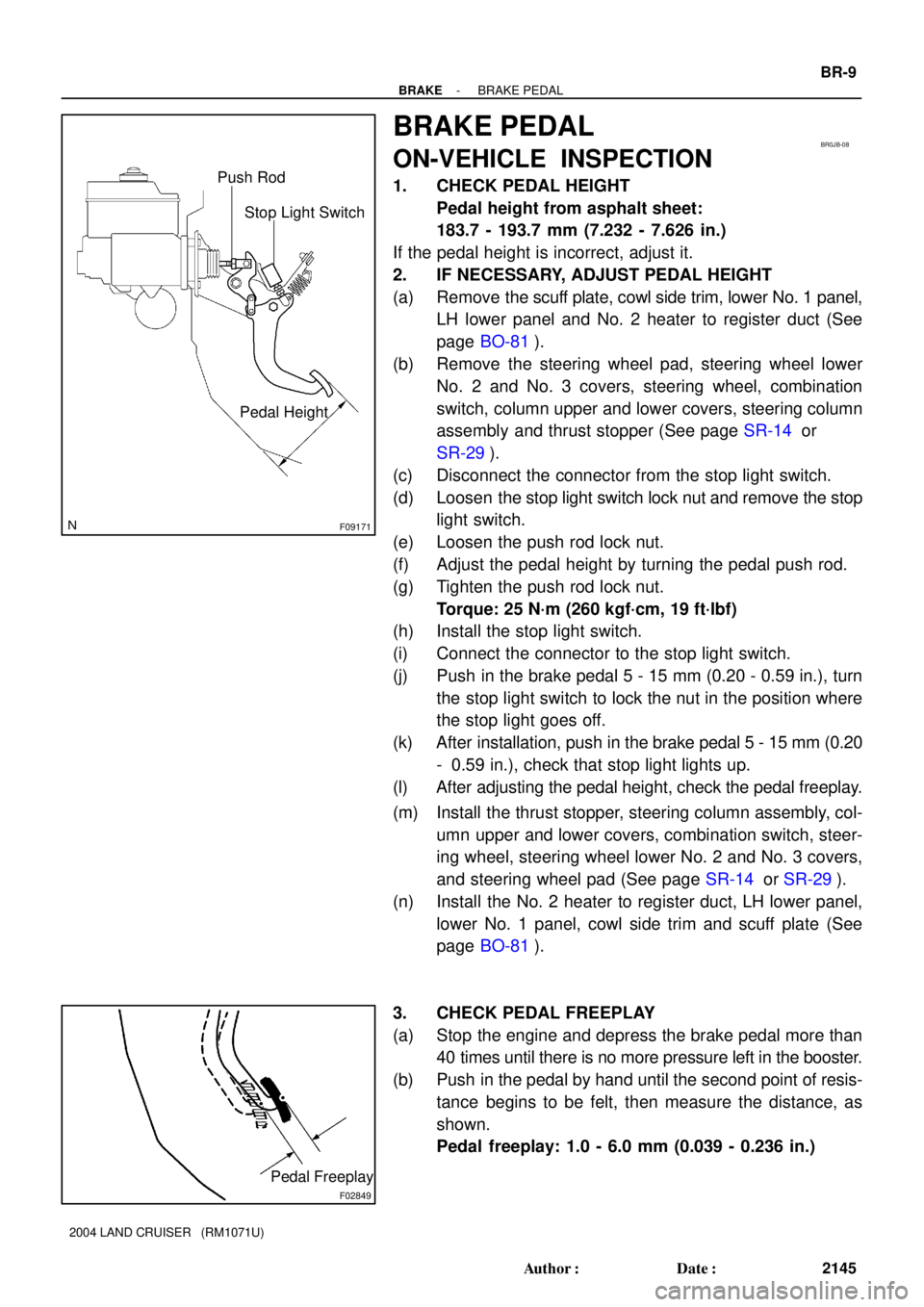
F09171
Stop Light Switch Push Rod
Pedal Height
BR0JB-08
F02849
Pedal Freeplay
- BRAKEBRAKE PEDAL
BR-9
2145 Author�: Date�:
2004 LAND CRUISER (RM1071U)
BRAKE PEDAL
ON-VEHICLE INSPECTION
1. CHECK PEDAL HEIGHT
Pedal height from asphalt sheet:
183.7 - 193.7 mm (7.232 - 7.626 in.)
If the pedal height is incorrect, adjust it.
2. IF NECESSARY, ADJUST PEDAL HEIGHT
(a) Remove the scuff plate, cowl side trim, lower No. 1 panel,
LH lower panel and No. 2 heater to register duct (See
page BO-81).
(b) Remove the steering wheel pad, steering wheel lower
No. 2 and No. 3 covers, steering wheel, combination
switch, column upper and lower covers, steering column
assembly and thrust stopper (See page SR-14 or
SR-29).
(c) Disconnect the connector from the stop light switch.
(d) Loosen the stop light switch lock nut and remove the stop
light switch.
(e) Loosen the push rod lock nut.
(f) Adjust the pedal height by turning the pedal push rod.
(g) Tighten the push rod lock nut.
Torque: 25 N´m (260 kgf´cm, 19 ft´lbf)
(h) Install the stop light switch.
(i) Connect the connector to the stop light switch.
(j) Push in the brake pedal 5 - 15 mm (0.20 - 0.59 in.), turn
the stop light switch to lock the nut in the position where
the stop light goes off.
(k) After installation, push in the brake pedal 5 - 15 mm (0.20
- 0.59 in.), check that stop light lights up.
(l) After adjusting the pedal height, check the pedal freeplay.
(m) Install the thrust stopper, steering column assembly, col-
umn upper and lower covers, combination switch, steer-
ing wheel, steering wheel lower No. 2 and No. 3 covers,
and steering wheel pad (See page SR-14 or SR-29).
(n) Install the No. 2 heater to register duct, LH lower panel,
lower No. 1 panel, cowl side trim and scuff plate (See
page BO-81).
3. CHECK PEDAL FREEPLAY
(a) Stop the engine and depress the brake pedal more than
40 times until there is no more pressure left in the booster.
(b) Push in the pedal by hand until the second point of resis-
tance begins to be felt, then measure the distance, as
shown.
Pedal freeplay: 1.0 - 6.0 mm (0.039 - 0.236 in.)
Page 535 of 3115
BR0TA-04
F04974
F04975
- BRAKEFRONT BRAKE CALIPER
BR-19
2155 Author�: Date�:
2004 LAND CRUISER (RM1071U)
REMOVAL
1. REMOVE FRONT WHEEL
Torque: 103 N´m (1,050 kgf´cm, 76 ft´lbf)
2. DISCONNECT BRAKE LINE
(a) Remove the union bolt and 2 gaskets from the caliper,
then disconnect the flexible hose from the caliper.
Torque: 30 N´m (310 kgf´cm, 22 ft´lbf)
(b) Use a container to catch the brake fluid as it drains out.
3. REMOVE CALIPER
Remove the 2 mounting bolts and remove the caliper.
Torque: 123 N´m (1,250 kgf´cm, 90 ft´lbf)
4. REMOVE CLIP AND 2 PINS
5. REMOVE 2 PAD RETAINER CLIPS
6. REMOVE 2 PADS, ANTI-SQUEAL SHIMS AND PAD
RETAINERS
Page 538 of 3115
- BRAKEFRONT BRAKE PAD
BR-17
2153 Author�: Date�:
2004 LAND CRUISER (RM1071U)
NOTICE:
There should be no oil or grease adhering to the friction
surfaces of the pads or the disc.
8. INSTALL 2 PAD RETAINER CLIPS AND 2 PINS
9. INSTALL CLIP
10. INSTALL FRONT WHEEL
Torque: 103 N´m (1,050 kgf´cm, 76 ft´lbf)
11. DEPRESS BRAKE PEDAL SEVERAL TIMES
12. CHECK THAT FLUID LEVEL IS AT MAX LINE
Page 572 of 3115

BR0TD-06
F04984
F05028
F04985
SSTSSTRemoval:
Installation:
F04986
BR-34
- BRAKEPARKING BRAKE
2170 Author�: Date�:
2004 LAND CRUISER (RM1071U)
DISASSEMBLY
1. REMOVE REAR WHEEL
Torque: 103 N´m (1,050 kgf´cm, 76 ft´lbf)
2. REMOVE REAR DISC BRAKE ASSEMBLY
(a) Remove the 2 mounting bolts and remove the disc brake
assembly.
Torque: 103 N´m (1,050 kgf´cm, 76 ft´lbf)
(b) Suspend the disc brake securely. Ensure that the hose is
not stretched.
3. REMOVE DISC
(a) Place matchmarks on the disc and rear hub.
(b) Remove the disc.
HINT:
If the disc cannot be removed easily, turn the shoe adjuster until
the wheel turns freely.
4. REMOVE TENSION SPRING
(a) Using needle-nose pliers, remove the spring from the
rear shoe and backing plate.
(b) Remove the lower side tension spring.
5. REMOVE SHOE RETURN SPRINGS
Using SST, remove the 2 shoe return springs.
SST 09717-20010
HINT:
At the time of installation, using SST, install the rear shoe return
spring and then install the front shoe return spring.
SST 09718-20010
6. REMOVE SHOE STRUT WITH SPRING
7. REMOVE REAR SHOE, ADJUSTER AND TENSION
SPRING
(a) Slide out the rear shoe and remove the adjuster.
(b) Remove the shoe hold-down spring, 2 cups and pin.