Page 2885 of 3115
F04396
F04395
- SUSPENSION AND AXLECOIL SPRING AND REAR SHOCK ABSORBER
SA-173
2123 Author�: Date�:
2004 LAND CRUISER (RM1071U)
7. REMOVE COIL SPRING
(a) Begin to lower the axle housing.
NOTICE:
Be careful not to snap the brake line and parking brake
cable.
(b) While lowering the axle housing, remove the coil spring
and insulator.
HINT:
At the time of installation, please refer to the following items.
�Check that the coil spring end is installed correctly.
�If the coil spring end is not in the correct position, reinstall
the coil spring.
(c) Remove the bolt and follow spring from the frame.
Torque: 28 N´m (290 kgf´cm, 21 ft´lbf)
Page 2895 of 3115
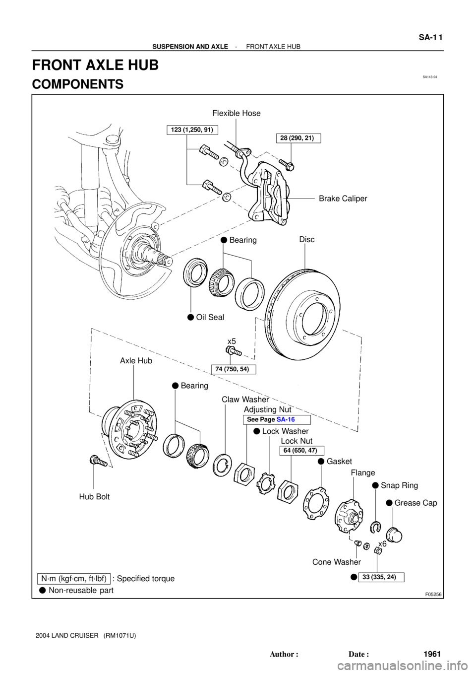
SA143-04
F05256
123 (1,250, 91)
74 (750, 54)
Disc
� Bearing
� Oil Seal
� Bearing
� Lock Washer
� Gasket
� Snap Ring Axle Hub
Hub BoltClaw Washer
Adjusting Nut
Lock Nut
Flange
� Grease Cap
33 (335, 24)
Brake Caliper
x6
� Non-reusable part
N´m (kgf´cm, ft´lbf) : Specified torquex5
28 (290, 21)
� Cone Washer
64 (650, 47)
Flexible Hose
See Page SA-16
- SUSPENSION AND AXLEFRONT AXLE HUB
SA-1 1
1961 Author�: Date�:
2004 LAND CRUISER (RM1071U)
FRONT AXLE HUB
COMPONENTS
Page 2898 of 3115

(d) Using a spring tension gauge, check the preload.
Preload (at starting):
42 - 67 N (")
F04362
90°
F04363
- SUSPENSION AND AXLEFRONT AXLE HUB
SA-17
1967 Author�: Date�:
2004 LAND CRUISER (RM1071U)
(d) Using a spring tension gauge, check the preload.
Preload (at starting):
42 - 67 N (4.3 - 6.8 kgf, 9.5 - 15.0 lbf)
HINT:
Make sure to check preload in the direction of rotation.
If the preload is not within the specified value, adjust it again
with the adjusting nut.
(e) Secure the lock nut by bending one of the lock washer
teeth inward and the other lock washer teeth outward.
4. INSTALL FLANGE
(a) Place a new gasket in position on the axle hub.
(b) Install the flange to the axle hub.
(c) Install the 6 cone washers, washers and new nuts.
Torque: 33 N´m (335 kgf´cm, 24 ft´lbf)
(d) Pull out the drive shaft to the outside of the vehicle and
select the snap ring which ensures the clearance be-
tween the tip of the flange and the snap ring is less than
0.2 mm (0.008 in.).
Snap ring thickness:
1.8 mm (0.0709 in.)2.4 mm (0.0945 in.)
2.0 mm (0.0787 in.)2.6 mm (0.1024 in.)
2.2 mm (0.0866 in.)2.8 mm (0.1102 in.)
(e) Using a snap ring expander, install a new snap ring to the
drive shaft.
(f) Install a new grease cap to the flange.
5. INSTALL BRAKE CALIPER
(a) Install the brake caliper, washers and 2 bolts.
Torque: 123 N´m (1,250 kgf´cm, 91 ft´lbf)
(b) Install the flexible hose and bolt to the steering knuckle.
Torque: 28 N´m (290 kgf´cm, 21 ft´lbf)
6. INSTALL FRONT WHEEL
Torque: 131 N´m (1,340 kgf´cm, 97 ft´lbf)
7. CHECK ABS SPEED SENSOR SIGNAL
(See page DI-505)
Page 2901 of 3115

REMOVAL
1. REMOVE FRONT WHEEL
2. REMOVE BRAKE CALIPER
(a) Remove t")
SA144-04
F04367
F04368
F04369
F04370SST SA-12
- SUSPENSION AND AXLEFRONT AXLE HUB
1962 Author�: Date�:
2004 LAND CRUISER (RM1071U)
REMOVAL
1. REMOVE FRONT WHEEL
2. REMOVE BRAKE CALIPER
(a) Remove the bolt and disconnect the flexible hose from
the steering knuckle.
(b) Remove the 2 bolts, washers and brake caliper.
(c) Support the brake caliper securely.
3. REMOVE FLANGE
(a) Using a screwdriver and hammer, remove the grease cap
from the flange.
(b) Using a snap ring expander, remove the snap ring.
(c) Remove the 6 nuts and washers.
(d) Install the 6 nuts temporarily to protect the threads of the
stud bolts.
(e) Using a brass bar and hammer, tap on the bolt heads and
remove the 6 nuts and cone washers.
(f) Remove the flange and gasket.
4. REMOVE AXLE HUB WITH DISC
(a) Using a screwdriver, release the lock washer.
(b) Using SST, remove the lock nut.
SST 09607-60020
(c) Remove the lock washer.
(d) Using SST, remove the adjusting nut.
SST 09607-60020
(e) Remove the axle hub with disc.
NOTICE:
Be careful not to damage the ABS speed sensor rotor and
oil seal.
(f) Remove the claw washer and bearing from the axle hub.
Page 2902 of 3115
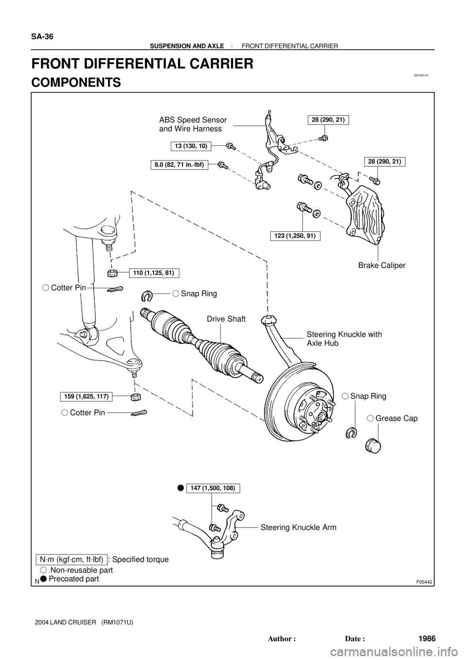
SA1SE-01
F05442
� Grease Cap
Steering Knuckle Arm
� Cotter Pin
Drive Shaft
N´m (kgf´cm, ft´lbf)� Snap Ring Steering Knuckle with
Axle HubBrake Caliper ABS Speed Sensor
and Wire Harness
� Cotter Pin
: Specified torque
� Non-reusable part
� Precoated part
28 (290, 21)
13 (130, 10)
8.0 (82, 71 in.´lbf)
110 (1,125, 81)
159 (1,625, 117)
147 (1,500, 108)
123 (1,250, 91)
28 (290, 21)
� � Snap Ring
SA-36
- SUSPENSION AND AXLEFRONT DIFFERENTIAL CARRIER
1986 Author�: Date�:
2004 LAND CRUISER (RM1071U)
FRONT DIFFERENTIAL CARRIER
COMPONENTS
Page 2926 of 3115
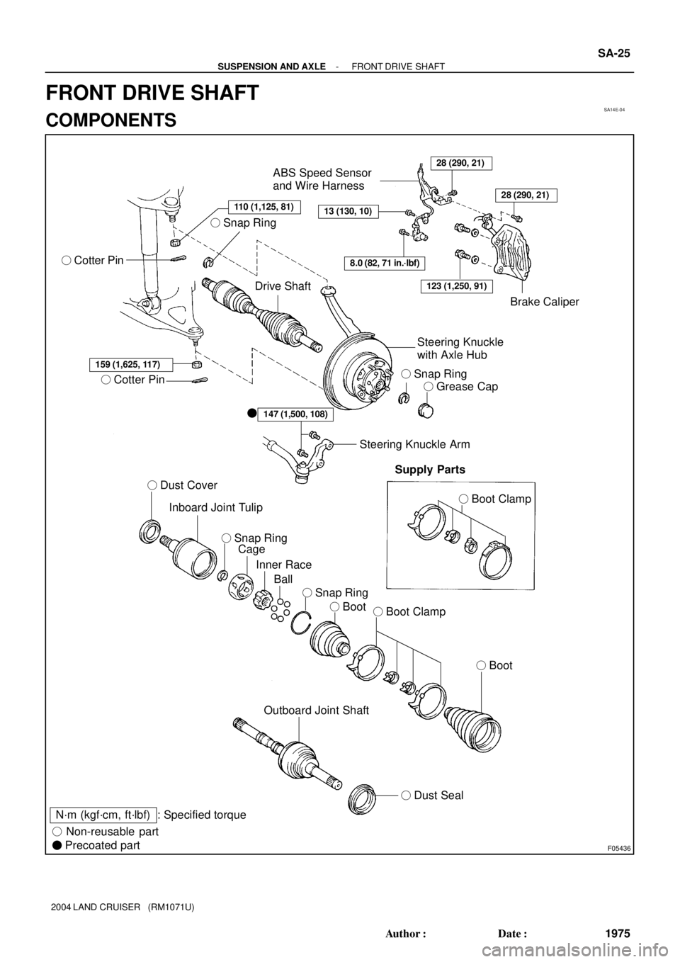
SA14E-04
F05436
110 (1,125, 81)
� Cotter Pin
Drive Shaft
28 (290, 21)
13 (130, 10)
ABS Speed Sensor
and Wire Harness
8.0 (82, 71 in.´lbf)
Brake Caliper
Steering Knuckle
with Axle Hub
� Snap Ring
� Grease Cap
159 (1,625, 117)
� Cotter Pin
� Dust Cover
Inboard Joint Tulip
Cage
Inner Race
Ball
� Boot� Boot Clamp
� Boot
147 (1,500, 108)�
Steering Knuckle Arm
Supply Parts
� Boot Clamp
Outboard Joint Shaft
� Dust Seal
N´m (kgf´cm, ft´lbf) : Specified torque
� Non-reusable part
� Precoated part
28 (290, 21)
123 (1,250, 91)
� Snap Ring � Snap Ring
� Snap Ring
- SUSPENSION AND AXLEFRONT DRIVE SHAFT
SA-25
1975 Author�: Date�:
2004 LAND CRUISER (RM1071U)
FRONT DRIVE SHAFT
COMPONENTS
Page 2932 of 3115

REMOVAL
1. REMOVE FRONT WHEEL
Torque: 131 N´m (1,340 kgf´cm")
SA14F-04
F04367
F04368
F05795
A
B
C
F05161
SA-26
- SUSPENSION AND AXLEFRONT DRIVE SHAFT
1976 Author�: Date�:
2004 LAND CRUISER (RM1071U)
REMOVAL
1. REMOVE FRONT WHEEL
Torque: 131 N´m (1,340 kgf´cm, 97 ft´lbf)
2. REMOVE BRAKE CALIPER
(a) Remove the bolt and disconnect the flexible hose from
the steering knuckle.
Torque: 28 N´m (290 kgf´cm, 21 ft´lbf)
(b) Remove the 2 bolts, washers and brake caliper.
Torque: 123 N´m (1,250 kgf´cm, 91 ft´lbf)
(c) Support the brake caliper securely.
3. REMOVE SNAP RING
(a) Using a screwdriver and hammer, remove the grease cap
from the flange.
(b) Using snap ring pliers, remove the snap ring.
4. DISCONNECT ABS SPEED SENSOR AND WIRE HAR-
NESS
Remove the 3 bolts and disconnect the ABS speed sensor and
wire harness.
Torque:
A: 8.0 N´m (82 kgf´cm, 71 in.´lbf)
B: 13 N´m (130 kgf´cm, 10 ft´lbf)
C: 28 N´m (290 kgf´cm, 21 ft´lbf)
5. DISCONNECT STEERING KNUCKLE ARM
Remove the 2 bolts and disconnect the steering knuckle arm.
Torque: 147 N´m (1,500 kgf´cm, 108 ft´lbf)
HINT:
At the time of installation, please refer to the following items.
�Clean the threads of the 2 bolts and steering knuckle with
toluene or trichloroethylene.
Page 2935 of 3115
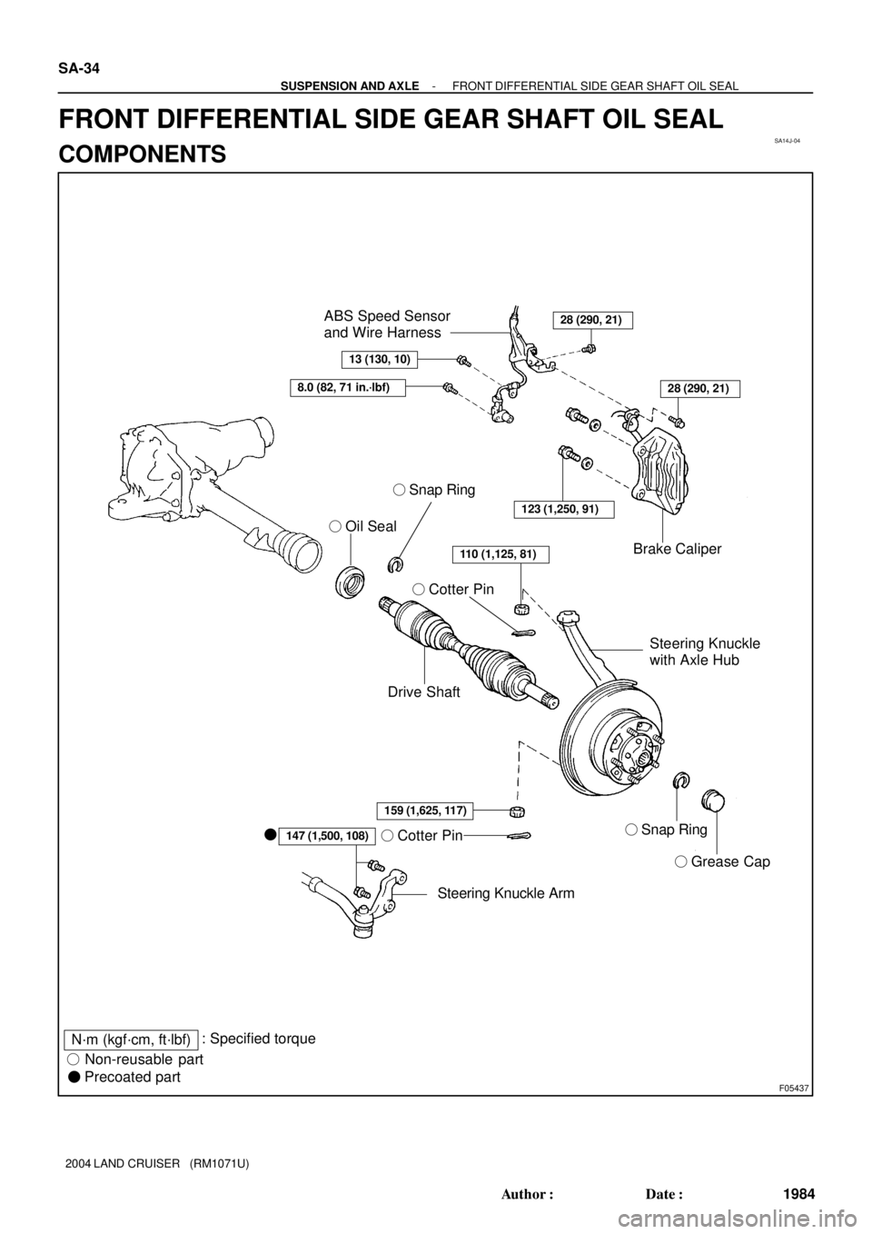
SA14J-04
F05437
� Oil Seal
Drive Shaft� Cotter PinBrake Caliper
Steering Knuckle
with Axle Hub
� Snap Ring
� Cotter Pin
� Grease Cap
Steering Knuckle Arm �
147 (1,500, 108)
123 (1,250, 91)
28 (290, 21)
8.0 (82, 71 in.´lbf)
13 (130, 10)
ABS Speed Sensor
and Wire Harness
28 (290, 21)
159 (1,625, 117)
110 (1,125, 81)
� Snap Ring
N´m (kgf´cm, ft´lbf): Specified torque
� Non-reusable part
� Precoated part SA-34
- SUSPENSION AND AXLEFRONT DIFFERENTIAL SIDE GEAR SHAFT OIL SEAL
1984 Author�: Date�:
2004 LAND CRUISER (RM1071U)
FRONT DIFFERENTIAL SIDE GEAR SHAFT OIL SEAL
COMPONENTS