Page 2962 of 3115

F05095
Camber
Caster (Example)
� = Calculated value
� = 0 point
0°00'
(0.0°)
0°10'
(0.17°) 0°20'
(0.34°)0°00'
(0.0°)
-0°10'
(-0.17°)
-0°20'
(-0.34°)
-3.2
-1.6
F05209
Camber
Caster(+)
(-) (-)
(+)
0°00'
(0.0°)0°20'
(0.34°) 0°00'
(0.0°)
-0°10'
(-0.17°) 0°10'
(0.17°)0°30'
(0.5°)0°40'
(0.67°)0°50'
(0.83°)1°00'
(1.0°) -0°10'
(-0.17°) -0°20'
(-0.34°) -0°30'
(-0.5°)
-0°20'
(-0.34°)
-0°30'
(-0.5°)
-0°40'
(-0.67°)
-0°50'
(-0.83°)
-1°00'
(-1.0°)
-1°10'
(-1.17°)
-1°20'
(-1.34°)
-1°30'
(-1.5°)
-1°40'
(-1.67°) 0°20'
(0.34°)
0°10'
(0.17°) 0°30'
(0.5°) 0°40'
(0.67°) 0°50'
(0.83°) 1°00'
(1.0°) 1°10'
(1.17°) 1°20'
(1.34°) 1°30'
(1.5°) 1°40'
(1.67°)
-1°00'
(-1.0°)-0°50'
(-0.83°)-0°40'
(-0.67°)
Front Cam Graduation
Rear Cam
Graduation SA-8
- SUSPENSION AND AXLEFRONT WHEEL ALIGNMENT
1958 Author�: Date�:
2004 LAND CRUISER (RM1071U)
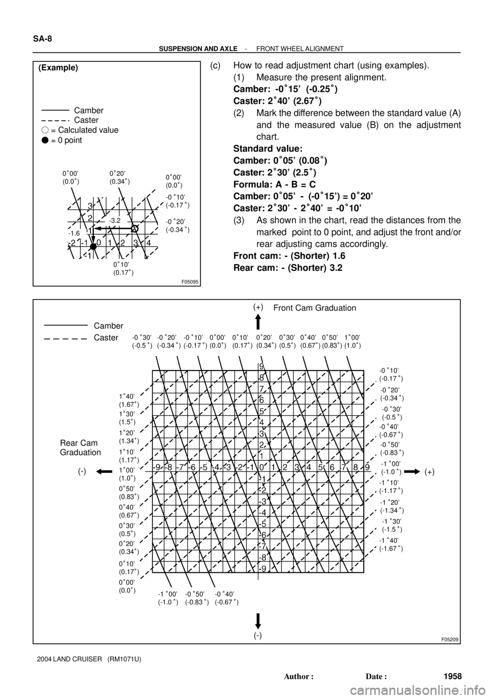
(c) How to read adjustment chart (using examples).
(1) Measure the present alignment.
Camber: -0°15' (-0.25°)
Caster: 2°40' (2.67°)
(2) Mark the difference between the standard value (A)
and the measured value (B) on the adjustment
chart.
Standard value:
Camber: 0°05' (0.08°)
Caster: 2°30' (2.5°)
Formula: A - B = C
Camber: 0°05' - (-0°15') = 0°20'
Caster: 2°30' - 2°40' = -0°10'
(3) As shown in the chart, read the distances from the
marked point to 0 point, and adjust the front and/or
rear adjusting cams accordingly.
Front cam: - (Shorter) 1.6
Rear cam: - (Shorter) 3.2
Page 2963 of 3115

SA3213
AB
CD
Front
F05208
- SUSPENSION AND AXLEFRONT WHEEL ALIGNMENT
SA-9
1959 Author�: Date�:
2004 LAND CRUISER (RM1071U)
(d) Torque the front and/or rear adjusting cam nuts.
Torque: 98 N´m (1,000 kgf´cm, 72 ft´lbf)
5. INSPECT TOE-IN
Toe-in:
Toe-in
(total)A + B: 0°06' ± 12' (0.1° ± 0.2°)
C - D: 1 ± 2 mm (0.04 ± 0.08 in.)
If the toe-in is not within the specified value, adjust it at the rack
ends.
6. ADJUST TOE-IN
(a) Check or adjust the lengths of the rack ends, then adjust
the toe-in.
Rack end length difference: 3.0 mm (0.118 in.) or less
(b) Remove the boot clamps.
(c) Loosen the tie rod end lock nuts.
(d) Turn the right and left rack ends by an equal amount to
adjust the toe-in.
HINT:
Try to adjust the toe-in to the center of the specified value.
(e) Tighten the tie rod end lock nuts.
Torque: 55 N´m (560 kgf´cm, 41 ft´lbf)
(f) Place the boots on the seats and install the clamps.
HINT:
Make sure that the boots are not twisted.
(g) Perform the zero point calibration of yaw rate and decel-
eration sensor (See page DI-505).
Page 2964 of 3115
SA0028
AB
FrontBA
A: Inside
B: Outside
F05200
SA-10
- SUSPENSION AND AXLEFRONT WHEEL ALIGNMENT
1960 Author�: Date�:
2004 LAND CRUISER (RM1071U)
7. INSPECT AND ADJUST WHEEL ANGLE
(a) Turn the steering wheel fully, and measure the turning
angle.
Wheel turning angle:
Inside wheel36°42' (33°42' - 36°42')
36.7° (33.7° - 36.7°)
Outside wheel: Reference32°36'
32.6°
If the right and left inside wheel angles differ from the specified
value, check the right and left rack end lengths.
(b) When toe-in is normal after inspection, adjust wheel
angle with the knuckle stopper bolt of the lower suspen-
sion arm.
Torque: 44 N´m (450 kgf´cm, 32 ft´lbf)
Page 3062 of 3115

SA140-09
- SUSPENSION AND AXLETROUBLESHOOTING
SA-1
1951 Author�: Date�:
2004 LAND CRUISER (RM1071U)
TROUBLESHOOTING
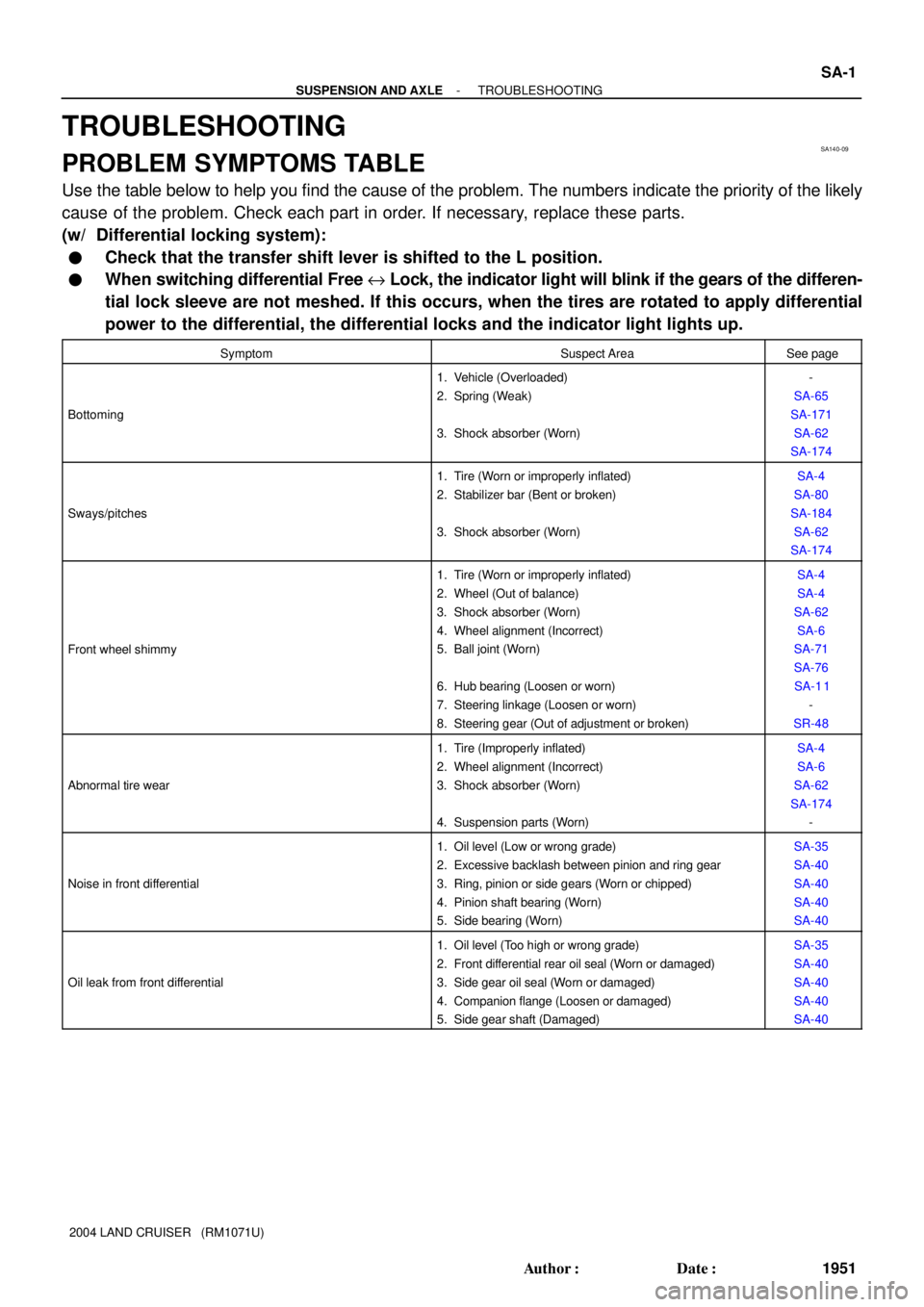
PROBLEM SYMPTOMS TABLE
Use the table below to help you find the cause of the problem. The numbers indicate the priority of the likely
cause of the problem. Check each part in order. If necessary, replace these parts.
(w/ Differential locking system):
�Check that the transfer shift lever is shifted to the L position.
�When switching differential Free e Lock, the indicator light will blink if the gears of the differen-
tial lock sleeve are not meshed. If this occurs, when the tires are rotated to apply differential
power to the differential, the differential locks and the indicator light lights up.
SymptomSuspect AreaSee page
Bottoming
1. Vehicle (Overloaded)
2. Spring (Weak)
3. Shock absorber (Worn)-
SA-65
SA-171
SA-62
SA-174
Sways/pitches
1. Tire (Worn or improperly inflated)
2. Stabilizer bar (Bent or broken)
3. Shock absorber (Worn)SA-4
SA-80
SA-184
SA-62
SA-174
Front wheel shimmy
1. Tire (Worn or improperly inflated)
2. Wheel (Out of balance)
3. Shock absorber (Worn)
4. Wheel alignment (Incorrect)
5. Ball joint (Worn)
6. Hub bearing (Loosen or worn)
7. Steering linkage (Loosen or worn)
8. Steering gear (Out of adjustment or broken)SA-4
SA-4
SA-62
SA-6
SA-71
SA-76
SA-1 1
-
SR-48
Abnormal tire wear
1. Tire (Improperly inflated)
2. Wheel alignment (Incorrect)
3. Shock absorber (Worn)
4. Suspension parts (Worn)SA-4
SA-6
SA-62
SA-174
-
Noise in front differential
1. Oil level (Low or wrong grade)
2. Excessive backlash between pinion and ring gear
3. Ring, pinion or side gears (Worn or chipped)
4. Pinion shaft bearing (Worn)
5. Side bearing (Worn)SA-35
SA-40
SA-40
SA-40
SA-40
Oil leak from front differential
1. Oil level (Too high or wrong grade)
2. Front differential rear oil seal (Worn or damaged)
3. Side gear oil seal (Worn or damaged)
4. Companion flange (Loosen or damaged)
5. Side gear shaft (Damaged)SA-35
SA-40
SA-40
SA-40
SA-40
Page 3064 of 3115

SA28F-03
START
Preliminary Check
��Tire pressure
��Vehicle height
��Brake dragging ROAD TEST
Does the vehicle lead/pull?
Cross switch front tire & wheel
assemblies (left & right).
Does the vehicle lead/pull in
same direction as before?
Check front wheel alignment.
Is it within specification?
Adjust front wheel alignment.Reverse the front left side
tire and rebalance it.
Does the vehicle
lead/pull to the left?
COMPLETE
Are the tires uni-directional type?
Choose the position of front tire & wheel
assemblies where there is least amount of pull.
Increase left front camber and decrease
right front camber until lead/pull is eliminated.Increase right front camber and decrease
left front camber until lead/pull is eliminated.
NO
YES
YES
NO
YES
YES
NO
YES
NO COMPLETE
NONOYES NOIs there steering
off center?
Adjust front tie rods.
NO
YES
Is the lead/pull stronger
than before?
YES
NOTICE : Do not exceed 1° of cross camber.
Do not exceed adjustment range.
Select a flat road where the vehicle can be driven in a straight line for 100 meters at a constant speed
of 35mph. Please confirm safety and set the steering wheel to its straight position. Drive the vehicle in
a straight line for 100 meters at a constant speed of 35mph without holding the steering wheel.
(1) The vehicle can keep straight but the steering wheel has some angle.
STEERING OFF CENTER (See page SR-10)
(2) The vehicle cannot keep straight.
STEERING PULL
YES NO
YES ROAD TEST
Does the vehicle still lead/pull?
NO ROAD TEST
Does the vehicle still lead/pull? ROAD TEST
Does the vehicle still lead/pull?
ROAD TEST
Does the vehicle still lead/pull?NO
Contact your local retail tire distributor.YES
*
*
- SUSPENSION AND AXLETROUBLESHOOTING
SA-3
1953 Author�: Date�:
2004 LAND CRUISER (RM1071U)
REPAIR PROCEDURES
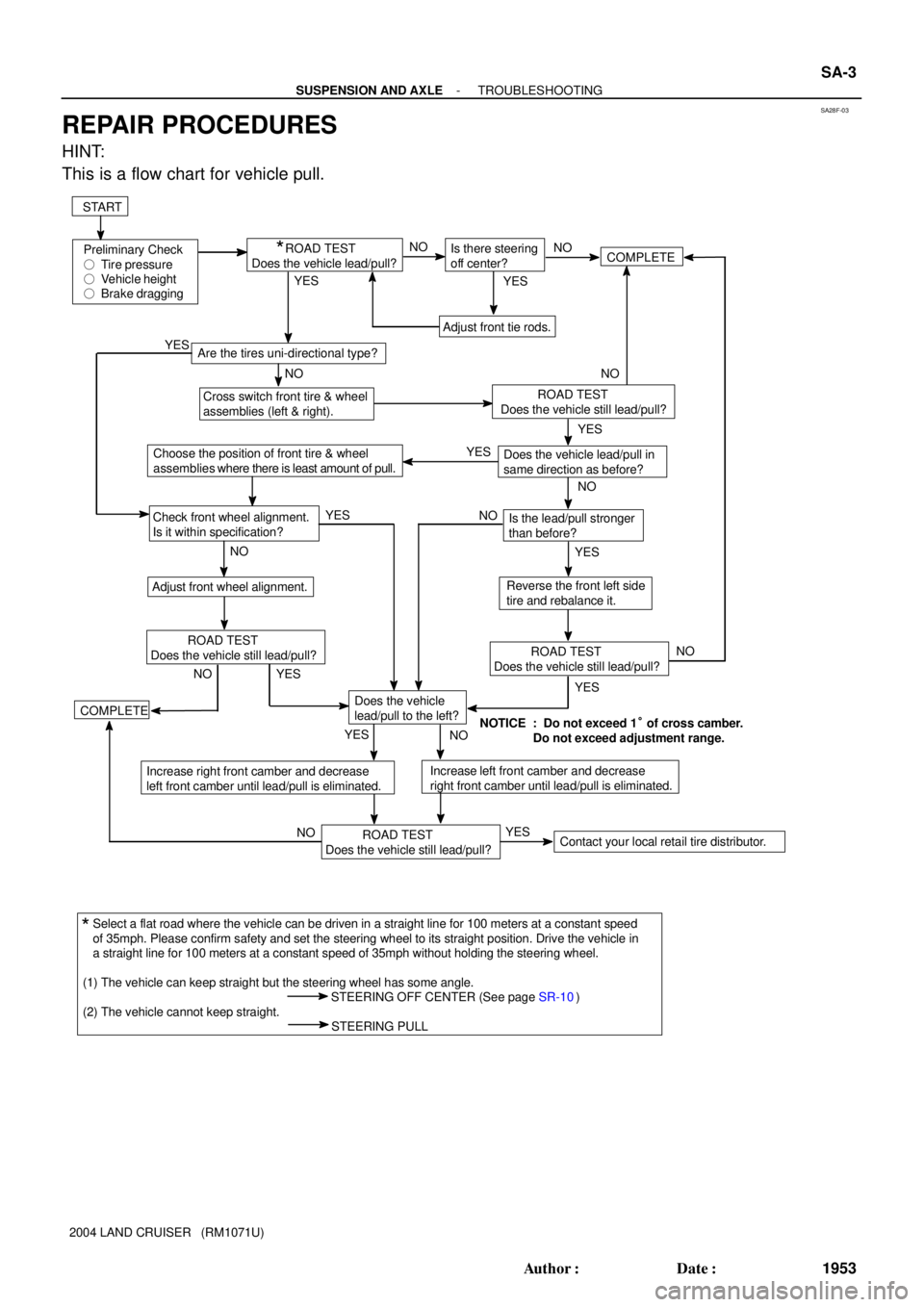
HINT:
This is a flow chart for vehicle pull.