Page 179 of 3115
Malfunction due to mechanical fail-
ure.Replace radio receiver assembly.
63 (In-dash CD
auto changer)42 No Disc
ReadoutDisc cannot be read. Inspect CD.
63")
EJECT
Malfunction 41 61
(Cassette
switch)Malfunction due to mechanical fail-
ure.Replace radio receiver assembly.
63 (In-dash CD
auto changer)42 No Disc
ReadoutDisc cannot be read. Inspect CD.
63 (In-dash CD
auto changer)44
CD Error
Error is detected in CD auto
changer.Replace radio receiver assembly.
Physical address: 440 Strereo component amplifier
01
(Communica-
tion Control)22 RAM Error
01
(Communica-
tion Control)D6
*1Absence of
MasterComponent in which this code is re-
corded has been disconnected from
system with ignition in ACC or ON.
Or, when this code was recorded, ra-
dio receiver assembly was discon-
nected.� Check harness for power supply of
radio receiver assembly.
� Check harness for communication
system of radio receiver assembly.
� Check harness for power supply of
stereo component amplifier.
� Check harness for communication
system of stereo component ampli-
fier. HINT:
*1: Even if no failure is detected, it may be stored depending on the battery condition or voltage for starting an engine.
*2: It may be stored when the engine key is turned 1 min. angain after engine start.
*3: It may be stored when the engine key is turned again after engine start.
*4: When 210 sec. has passed after pulling out the power supply connector of the master component with the ignition
switch in ACC or ON, this code is stored.
Logical addressDTC
Diagnosis itemDiagnosis content
Countermeasure and inspeced parts
01
(Communica-
tion Control)21 ROM Error Abnormal condition of ROM is
detected.Replace stereo component
amplifier.
Abnormal condition of RAM is
detected.Replace stereo component
amplifier.
63
(In-dash CD auto
Changer)45EJECT Error
CD cannot be ejected.
Replace radio receiver assembly.
63
(In-dash CD auto
Changer)47 CD High Temp.
High temperature is detected in
CD auto changer.Replace radio receiver assembly.
63
(In-dash CD auto
Changer)48CD Excess
CurrentExcess current is applied to CD
auto changer.Replace radio receiver assembly.
Mechanical or
Media Error 40 61
(Cassette
switch)Inspect cassette tape. Malfunction due to mechanical fail-
ure is identified. Or, cassette tape is
cut or entangled.
- BODY ELECTRICALAUDIO SYSTEM
BE-143
2516 Author�: Date�:
2004 LAND CRUISER (RM1071U)
Page 1415 of 3115
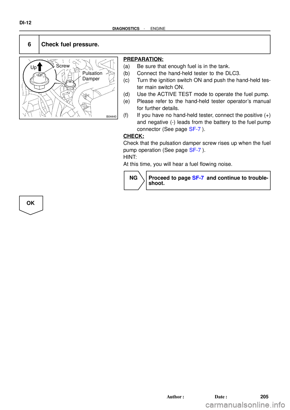
B04440
UpScrew
Pulsation
Damper
DI-12
- DIAGNOSTICSENGINE
205 Author�: Date�:
6 Check fuel pressure.
PREPARATION:
(a) Be sure that enough fuel is in the tank.
(b) Connect the hand-held tester to the DLC3.
(c) Turn the ignition switch ON and push the hand-held tes-
ter main switch ON.
(d) Use the ACTIVE TEST mode to operate the fuel pump.
(e) Please refer to the hand-held tester operator's manual
for further details.
(f) If you have no hand-held tester, connect the positive (+)
and negative (-) leads from the battery to the fuel pump
connector (See page SF-7).
CHECK:
Check that the pulsation damper screw rises up when the fuel
pump operation (See page SF-7).
HINT:
At this time, you will hear a fuel flowing noise.
NG Proceed to page SF-7 and continue to trouble-
shoot.
OK
Page 2647 of 3115
SST
(Adaptor)
SST
(Union)
Front Fuel Pipe
Gasket
- SFIFUEL PUMP
SF-7
1706 Author�: Date�:
2004 LAND CRUIS")
A07061
TOYOTA
Hand-Held
Tester
DLC3SF10V-02
B04440
Up
Pulsation
Damper
Screw
B04441
SST
(Gauge)SST
(Adaptor)
SST
(Union)
Front Fuel Pipe
Gasket
- SFIFUEL PUMP
SF-7
1706 Author�: Date�:
2004 LAND CRUISER (RM1071U)
FUEL PUMP
ON-VEHICLE INSPECTION
1. CHECK FUEL PUMP OPERATION
(a) Connect a TOYOTA hand-held tester or OBD II scan tool
to the DLC3.
(b) Turn the ignition switch ON, and press the TOYOTA
hand-held tester or OBD II scan tool main switch ON.
NOTICE:
Do not start the engine.
(c) Select the ACTIVE TEST mode on the TOYOTA hand-
held tester or OBD II scan tool.
(d) Please refer to the TOYOTA hand-held tester or OBD II
scan tool operator's manual for further details.
(e) If you have no TOYOTA hand-held tester or OBD II scan
tool, connect the positive (+) and negative (-) leads from
the battery to the fuel pump connector. (See step 3)
(f) Disconnect the fuel return hose from the clamp on the V-
bank cover.
(g) Remove the 2 bolts, nuts and V-bank cover.
(h) Check that the pulsation damper screw pop up when the
fuel pump operates.
If operation is not as specified, check following parts:
�Fusible link
�Fuses
�EFI main relay
�Fuel pump
�ECM
�Wiring connections
(i) Turn the ignition switch OFF.
(j) Disconnect the TOYOTA hand-held tester or OBD II scan
tool from the DLC3.
2. CHECK FUEL PRESSURE
(a) Check the battery positive voltage is above 12 V.
(b) Disconnect the negative (-) terminal cable from the bat-
tery.
(c) Remove the front fuel pipe from the LH delivery pipe (See
page SF-22).
(d) Install the front fuel pipe and SST (pressure gauge) to the
delivery pipe with the 3 lower gaskets and SST (adaptor).
SST 09268-45014 (09268-41190, 90405-06167)
Torque: 39 N´m (400 kgf´cm, 29 ft´lbf)
(e) Wipe off any splattered gasoline.
(f) Reconnect the negative (-) terminal cable to the battery.
(g) Connect a TOYOTA hand-held tester or OBD II scan tool
to the DLC3 (See (a) to (e) in step 1 on the check fuel
pump operation).
(h) Measure the fuel pressure.