Page 1214 of 3115

INSPECTION PROCEDURE
HINT:
Read freeze frame data using the hand-held tester o")
A19522A19630
E5E7E1
FPR
ECM Connector
A21024
- DIAGNOSTICSENGINE
DI-165
358 Author�: Date�:
2004 LAND CRUISER (RM1071U)
INSPECTION PROCEDURE
HINT:
Read freeze frame data using the hand-held tester or the OBD II scan tool. Freeze frame data records the
engine conditions when a malfunction is detected. When troubleshooting, freeze frame data can help deter-
mine if the vehicle was running or stopped, if the engine was warmed up or not, if the air-fuel ratio was lean
or rich, as well as other data from the time when a malfunction occurred.
1 Check voltage between terminal FPR and E1 of ECM.
CHECK:
Measure the voltage between terminals of E5 and E7 ECM con-
nectors.
OK:
Tester ConnectionConditionSpecified Condition
FPR (E5-33) - E1 (E7-1)STA signal ON9 to 14 V
FPR (E5-33) - E1 (E7-1)STA signal OFF0 to 3 V
OK Replace ECM (See page SF-60).
NG
2 Check fuel pump relay.
PREPARATION:
Remove the fuel pump relay from the engine room R/B.
CHECK:
Inspect the fuel pump relay.
OK:
Tester ConnectionSpecified Condition
1 - 2Continuity
3 - 4Continuity
3 - 5 No continuity
3 - 5Continuity
(Apply battery voltage terminal 1 and 2)
NG Replace fuel pump relay.
OK
Page 1215 of 3115
A21342
Engine Room J/B:
Fuel Pump
Relay
A21023
E5
ECM Connector FPR
DI-166
- DIAGNOSTICSENGINE
359 Author�: Date�:
2004 LAND CRUISER (RM1071U)
3 Check for open and short in harness and connector between fuel pump relay
and ECM.
PREPARATION:
(a) Remove the fuel pump relay from the engine room J/B.
(b) Disconnect the E5 ECM connector.
CHECK:
Measure the resistance between wire harness side connectors.
OK:
Tester ConnectionSpecified Condition
Engine Room J/B (Fuel pump relay ter-
minal 1) - FPR (E5-33)Below 1 W
Engine Room J/B (Fuel pump relay ter-
minal 1) or FPR (E5-33) -
Body ground
10 kW or higher
NG Repair or replace harness or connector.
OK
Replace ECM (See page SF-60).
Page 1276 of 3115
A19970A20087
V1 Vapor Pressure Sensor
Cowl Side J/B LH
Engine Room R/B
Engine Room J/B
F15 FL BlockECM
J/B No. 5
MAIN
BatteryEFI or
ECD No. 2
EFI or ECD RelayJ/B No. 6 J/B No. 5
V4
VSV (EVAP)
MREL CCV
PRG TBP PTNK E2VC
V10 VSV (Pressure
Switching Valve)
VCC
GND
PTNK4
BB1 ID4 Id1 IN2 If1
BB1 ID4 Id1 IN2 If1
BB1 ID4
BD3 BD3 ID4
IX2E5
E5
E5
E5 E9
E9
2A
2K2B 2Q
11
1 11B
1B1A
1CE9
5D5C 6C 6D 5D 5C L-R
3
1
2
BR-W
L-BBR-WL-R L-R L-R L-R L-R
L-B L-BBR BR BR-W BR-W
B-Y L-R L-R L-RLL L B-Y B-Y
SB
SB
B-Y
B-YB-Y B-Y L-B
B-W B-W
B-Y
B-W W-B W-B
B-G
2
EA 7
3
111
14
121
23
13418
28
21
4
27
34 12
1 2 11078 9
45
10
165
15
28
44 43
11 1EFI or ECD No. 1 1221 13
1
2 3
4
B-YL-R
If1 14
V9 VSV (Canister
Closed Valve)
- DIAGNOSTICSENGINE
DI-227
420 Author�: Date�:
WIRING DIAGRAM
Page 1279 of 3115
DI-230
- DIAGNOSTICSENGINE
423 Author�: Date�:
6 Check vacuum hose between intake manifold and EVAP VSV, and EVAP VSV and
charcoal canister.
CHECK:
(a) Check that the vacuum hose is connected correctly.
(b) Check the vacuum hose for looseness and disconnection.
(c) Check the vacuum hose for cracks, hole, damage and blockage.
NG Repair or replace vacuum hose.
OK
7 Check operation of EVAP VSV (See page SF-44).
NG Replace EVAP VSV.
OK
8 Check for open and short in harness and connector between EFI or ECD relay
and EVAP VSV, and EVAP VSV and ECM (See page IN-36).
NG Repair or replace harness or connector.
OK
Replace ECM (See page SF-60).
Page 1281 of 3115
BE6653A10143A10144A10801VSV is ONVSV is OFF ON
Air
Air
E
FE
F
DI-232
- DIAGNOSTICSENGINE
425 Author�: Date�:
12 Check for open and short in harness and connector between EFI or ECD relay
and CCV, and CCV and ECM (See page IN-36).
NG Repair or replace harness or connector.
OK
Replace ECM (See page SF-60).
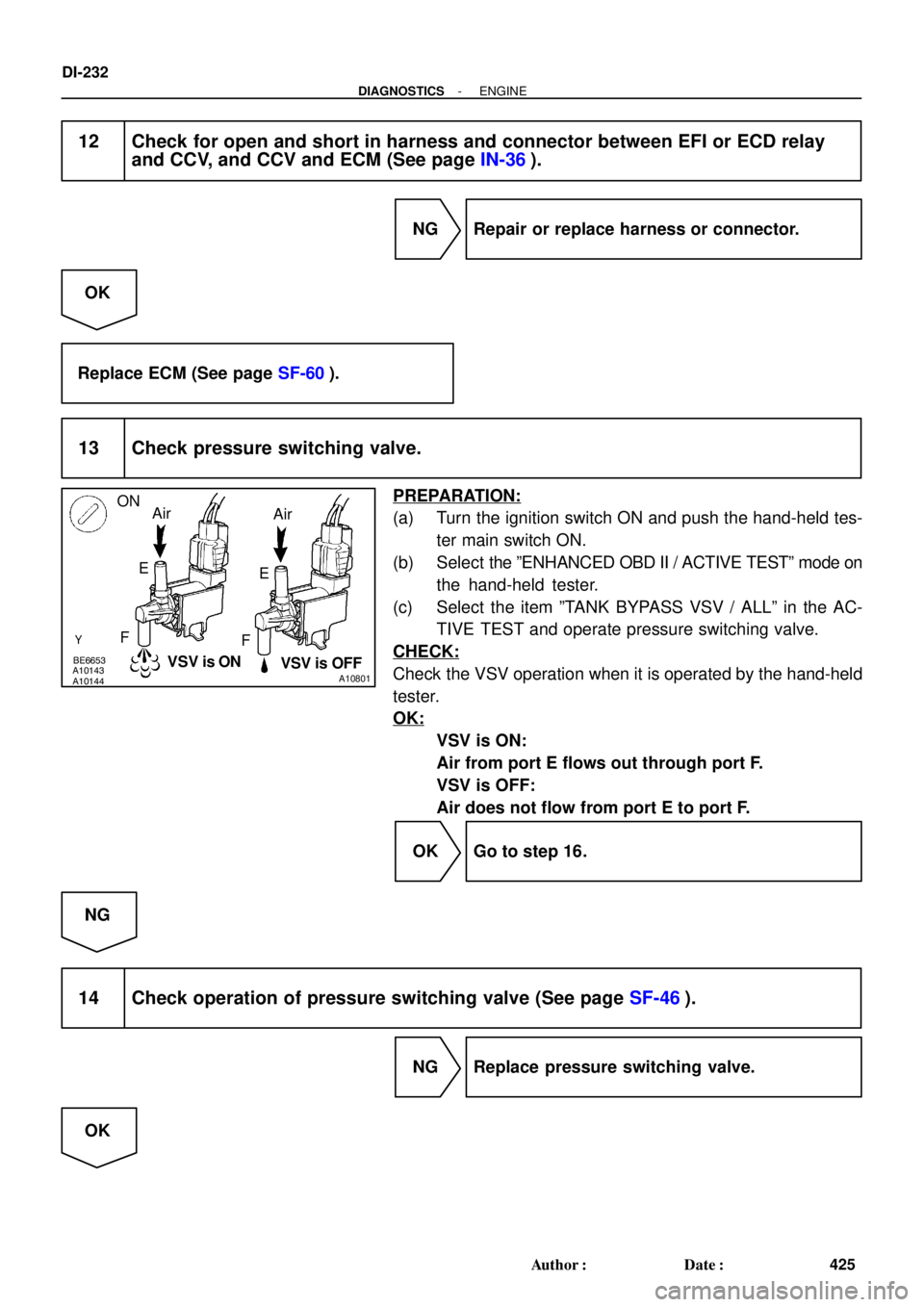
13 Check pressure switching valve.
PREPARATION:
(a) Turn the ignition switch ON and push the hand-held tes-
ter main switch ON.
(b) Select the ºENHANCED OBD II / ACTIVE TESTº mode on
the hand-held tester.
(c) Select the item ºTANK BYPASS VSV / ALLº in the AC-
TIVE TEST and operate pressure switching valve.
CHECK:
Check the VSV operation when it is operated by the hand-held
tester.
OK:
VSV is ON:
Air from port E flows out through port F.
VSV is OFF:
Air does not flow from port E to port F.
OK Go to step 16.
NG
14 Check operation of pressure switching valve (See page SF-46).
NG Replace pressure switching valve.
OK
Page 1282 of 3115
A10193
A20058
- DIAGNOSTICSENGINE
DI-233
426 Author�: Date�:
15 Check for open and short in harness and connector between EFI or ECD relay
and pressure switching valve, and pressure switching valve and ECM (See page
IN-36).
NG Repair or replace harness or connector.
OK
Replace ECM (See page SF-60).
16 Check whether hose close to fuel tank has been modified, and check whether
there are signs of any accident near fuel tank.
CHECK:
Check for cracks, deformation and loose connection of the fol-
lowing parts:
�Fuel tank
�Fuel tank filler pipe
�Hoses and tubes around fuel tank
NG Repair or replace evaporative emission leak
part.
OK
17 Check vacuum hoses between vapor pressure sensor and fuel tank, and char-
coal canister and pressure switching valve.
CHECK:
(a) Check that the vacuum hose is connected correctly.
(b) Check the vacuum hose for looseness and disconnection.
(c) Check the vacuum hose for cracks, hole and damage.
NG Repair or replace vacuum hose.
OK
Page 1291 of 3115
A19639VSV is OFF VSV is ON CCV
Air
E Air
E
FF
E5
DI-242
- DIAGNOSTICSENGINE
435 Author�: Date�:
16 Check for open and short in harness and connector between EFI or ECD relay
and EVAP VSV, and EVAP VSV and ECM (See page IN-36).
NG Repair or replace harness or connector.
OK
Replace ECM (See page SF-60).
17 Check CCV.
PREPARATION:
Turn the ignition switch ON.
CHECK:
Check the VSV function.
(1) Connect the terminal CCV of the ECM connector
and body ground (ON).
(2) Disconnect the terminal CCV of the ECM connector
and body ground (OFF).
OK:
(1) VSV is ON:
Air does not flow from port E to port F.
(2) VSV is OFF:
Air from port E flows out through port F.
OK Go to step 20.
NG
18 Check operation of CCV (See page SF-48).
NG Replace CCV.
OK
Page 1292 of 3115
A19641VSV is ON VSV is OFFTBP
Air
E Air
E
FF
E9
- DIAGNOSTICSENGINE
DI-243
436 Author�: Date�:
19 Check for open and short in harness and connector between EFI or ECD relay
and CCV, and CCV and ECM (See page IN-36).
NG Repair or replace harness or connector.
OK
Replace ECM (See page SF-60).
20 Check pressure switching valve.
PREPARATION:
Turn the ignition switch ON.
CHECK:
Check the VSV function.
(1) Connect the terminal TBP of the ECM connector
and body ground (ON).
(2) Disconnect the terminal TBP of the ECM connector
and body ground (OFF).
OK:
(1) VSV is ON:
Air does not flow from port E to port F.
(2) VSV is OFF:
Air from port E flows out through port F.
OK Go to step 23.
NG
21 Check operation of pressure switching valve (See page SF-46).
NG Replace pressure switching valve.
OK


MREL C")