Page 1346 of 3115
A21365
J/B No. 5
J/B No. 6ECM J17
J/C
Cowl Side J/B LH
Cowl Side J/B RH
ACC CUT Relay
J/B No. 6 Cowl Side J/B LH
ACC Relay
To
Audio
etc.
Engine Room R/B
Engine Room J/BSTARTER Relay
STARTERE6
E5
E7
E5 6D
6D
6D 6D
6C
6B
6B P
N 5C 5D
2A
2E
3C 3Q 3Q
3Q
6D 6B
2E
2E
2C
1
1
11
1B
1B
1B1D
1CIX1IX1
IX1
ED1
S1
S2 F15
F16
F17STAR
STA
STSW
ACCR
FL Block
MAIN
J/B No. 2
J/B No. 3ALTBatteryStarter9
17
12
15 A
A 9
614 15
3
16
5 6
4
7
AM2 ST2
AM1 ACC
2
3 78 14 3
10
41
1 5250
51
1 234
3
2
5
40
39
121
53 AM1
12
53 2
9 39
1
1
1
1 2
1
1 B-R
B-W
B-W
W-R
W-R
B-R
B-R B-W
SB
SB
B-G
SB
SB
R-G B
B
B-R
B-R
B-R
B-R SB
B-W
B-G
B-Y
W-BB-W
W-B
W-B W-RB-W
B-R B-G
B-G
B-GEE
IF 43
AM2
B-G
12
P1
Park/Neutral
Position SW
B-WB-R
B-R
B-WB-W
If1
If112
9
I18 Ignition SW
B 7A
7A
4 3
- DIAGNOSTICSENGINE
DI-297
490 Author�: Date�:
2004 LAND CRUISER (RM1071U)
WIRING DIAGRAM
Page 1385 of 3115

A19655A20059
STSW
ACCR
STAR
(NE)
Engine SpeedStarterPark/Neutral
Position SW
N P ST RelayACC Cut
Relay
Ignition
SW
ACC
ST2
ACCR
STSW
STAR BatteryECM
DI-336
- DIAGNOSTICSENGINE
529 Author�: Date�:
2004 LAND CRUISER (RM1071U)
Cranking Hold Function Circuit
CIRCUIT DESCRIPTION
The starter is controlled by the ECM, when the ECM detects a start signal (STSW) from the ignition switch,
this system monitors the engine speed (NE) and continues to operate the starter until it has determined that
the engine has started (engine speed reaches approximately 500 rpm). If the engine is already running and
the ignition switch is turned to START, the ECM will not operate the starter.
WIRING DIAGRAM
Refer to DTC P0617 on page DI-296.
INSPECTION PROCEDURE
Hand-held tester:
1 Check operation of engine cranking.
CHECK:
When turning the ignition switch to the START position, check whether the starter motor starts.
OK:
Starter motor starts.
OK Check for intermittent problems (See page
DI-3).
NG
DIC2U-01
Page 1387 of 3115
D06601
P1
Component Side:
Park/neutral Position Switch
DI-338
- DIAGNOSTICSENGINE
531 Author�: Date�:
2004 LAND CRUISER (RM1071U)
4 Check park/neutral position switch.
PREPARATION:
Remove the P1 park/neutral position switch connector.
CHECK:
Check continuity between each terminal shown below when the
shift lever is moved to each range.
Shift rangeTerminal No. to continuity
P1 - 36 - 9
R2 - 3-
N3 - 56 - 9
D3 - 7-
23 - 4-
L3 - 8-
OK:
There is continuity.
NG Replace the park/neutral position switch.
OK
Check and repair harness and connector be-
tween park/neutral position switch and ECM
(See page IN-36).
5 Check starter relay (See page ST-18).
NG Replace starter relay.
OK
6 Check for open and short in harness and connector between park/neutral posi-
tion switch and starter relay, starter relay and body ground (See page IN-36).
NG Repair or replace harness or connector.
OK
Page 1388 of 3115
A21347
Engine Room R/B
Starter Relay
- DIAGNOSTICSENGINE
DI-339
532 Author�: Date�:
2004 LAND CRUISER (RM1071U)
7 Check engine room R/B (Starter relay voltage).
PREPARATION:
Remove the starter relay from the engine room R/B.
CHECK:
Measure the voltage between the terminal of the engine room
R/B and body ground.
OK:
Tester ConnectionSpecified Condition
Starter relay (5) - Body ground9 to 14 V
NG Check and repair harness and connector be-
tween starter relay and battery.
OK
8 Check starter (See page ST-16).
NG Repair or replace starter.
OK
Page 1391 of 3115
A21347
Engine Room R/B
Starter Relay
DI-342
- DIAGNOSTICSENGINE
535 Author�: Date�:
2004 LAND CRUISER (RM1071U)
3 Check starter relay (See page ST-18).
NG Replace starter relay.
OK
4 Check for open and short in harness and connector between park/neutral posi-
tion switch and starter relay, starter relay and body ground (See page IN-36).
NG Repair or replace harness or connector.
OK
5 Check engine room R/B (Starter relay voltage).
PREPARATION:
Remove the starter relay from the engine room R/B.
CHECK:
Measure the voltage between the terminal of the engine room
R/B and body ground.
OK:
Tester ConnectionSpecified Condition
Starter relay (5) - Body ground9 to 14 V
NG Check and repair harness and connector be-
tween starter relay and battery (See page
IN-36).
OK
Page 1392 of 3115
D06601
Component Side
Park/neutral Position Switch
P1
- DIAGNOSTICSENGINE
DI-343
536 Author�: Date�:
2004 LAND CRUISER (RM1071U)
6 Check starter (See page ST-16).
NG Repair or replace starter.
OK
Check and repair harness and connector be-
tween starter relay and starter, starter and
battery (See page IN-36).
7 Check park/neutral position switch.
PREPARATION:
Remove the P1 park/neutral position switch connector.
CHECK:
Check continuity between each terminal shown below when the
shift lever is moved to each range.
Shift rangeTerminal No. to continuity
P1 - 36 - 9
R2 - 3-
N3 - 56 - 9
D3 - 7-
23 - 4-
L3 - 8-
OK:
There is continuity.
NG Replace the park/neutral position switch.
OK
Check and repair harness and connector be-
tween park/neutral position switch and ECM
(See page IN-36).
Page 1395 of 3115

DI1L4-19
DI-36
- DIAGNOSTICSENGINE
229 Author�: Date�:
2004 LAND CRUISER (RM1071U)
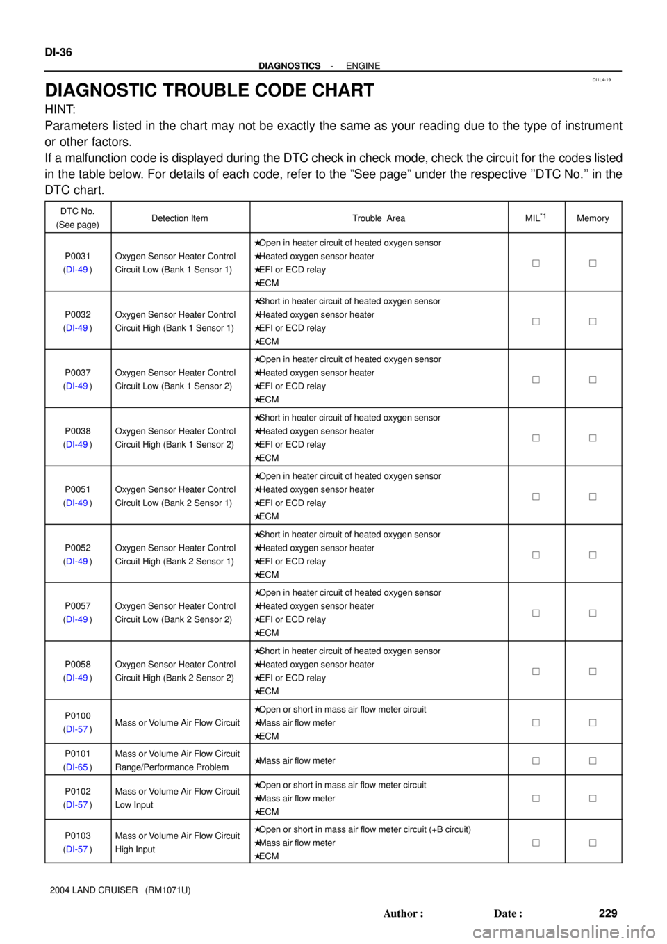
DIAGNOSTIC TROUBLE CODE CHART
HINT:
Parameters listed in the chart may not be exactly the same as your reading due to the type of instrument
or other factors.
If a malfunction code is displayed during the DTC check in check mode, check the circuit for the codes listed
in the table below. For details of each code, refer to the ºSee pageº under the respective ''DTC No.'' in the
DTC chart.
DTC No.
(See page)Detection ItemTrouble AreaMIL*1Memory
P0031
(DI-49)Oxygen Sensor Heater Control
Circuit Low (Bank 1 Sensor 1)
�Open in heater circuit of heated oxygen sensor
�Heated oxygen sensor heater
�EFI or ECD relay
�ECM
��
P0032
(DI-49)Oxygen Sensor Heater Control
Circuit High (Bank 1 Sensor 1)
�Short in heater circuit of heated oxygen sensor
�Heated oxygen sensor heater
�EFI or ECD relay
�ECM
��
P0037
(DI-49)Oxygen Sensor Heater Control
Circuit Low (Bank 1 Sensor 2)
�Open in heater circuit of heated oxygen sensor
�Heated oxygen sensor heater
�EFI or ECD relay
�ECM
��
P0038
(DI-49)Oxygen Sensor Heater Control
Circuit High (Bank 1 Sensor 2)
�Short in heater circuit of heated oxygen sensor
�Heated oxygen sensor heater
�EFI or ECD relay
�ECM
��
P0051
(DI-49)Oxygen Sensor Heater Control
Circuit Low (Bank 2 Sensor 1)
�Open in heater circuit of heated oxygen sensor
�Heated oxygen sensor heater
�EFI or ECD relay
�ECM
��
P0052
(DI-49)Oxygen Sensor Heater Control
Circuit High (Bank 2 Sensor 1)
�Short in heater circuit of heated oxygen sensor
�Heated oxygen sensor heater
�EFI or ECD relay
�ECM
��
P0057
(DI-49)Oxygen Sensor Heater Control
Circuit Low (Bank 2 Sensor 2)
�Open in heater circuit of heated oxygen sensor
�Heated oxygen sensor heater
�EFI or ECD relay
�ECM
��
P0058
(DI-49)Oxygen Sensor Heater Control
Circuit High (Bank 2 Sensor 2)
�Short in heater circuit of heated oxygen sensor
�Heated oxygen sensor heater
�EFI or ECD relay
�ECM
��
P0100
(DI-57)Mass or Volume Air Flow Circuit
�Open or short in mass air flow meter circuit
�Mass air flow meter
�ECM
��
P0101
(DI-65)Mass or Volume Air Flow Circuit
Range/Performance Problem�Mass air flow meter��
P0102
(DI-57)Mass or Volume Air Flow Circuit
Low Input�Open or short in mass air flow meter circuit
�Mass air flow meter
�ECM
��
P0103
(DI-57)Mass or Volume Air Flow Circuit
High Input�Open or short in mass air flow meter circuit (+B circuit)
�Mass air flow meter
�ECM
��
Page 1396 of 3115

- DIAGNOSTICSENGINE
DI-37
230 Author�: Date�:
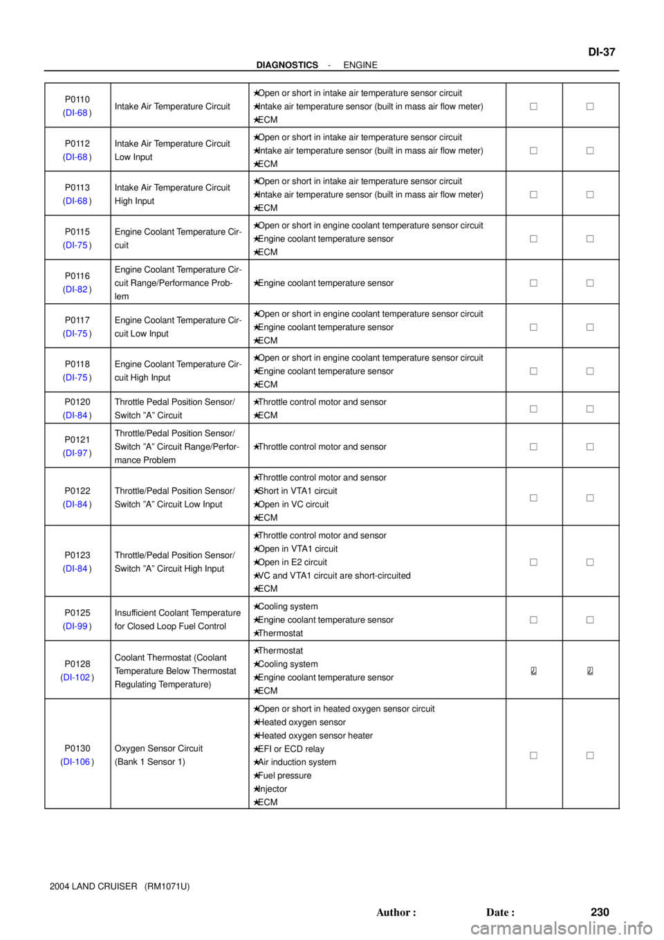
2004 LAND CRUISER (RM1071U)P0110
(DI-68)
Intake Air Temperature Circuit
�Open or short in intake air temperature sensor circuit
�Intake air temperature sensor (built in mass air flow meter)
�ECM
��
P0112
(DI-68)Intake Air Temperature Circuit
Low Input�Open or short in intake air temperature sensor circuit
�Intake air temperature sensor (built in mass air flow meter)
�ECM
��
P0113
(DI-68)Intake Air Temperature Circuit
High Input�Open or short in intake air temperature sensor circuit
�Intake air temperature sensor (built in mass air flow meter)
�ECM
��
P0115
(DI-75)Engine Coolant Temperature Cir-
cuit�Open or short in engine coolant temperature sensor circuit
�Engine coolant temperature sensor
�ECM
��
P0116
(DI-82)Engine Coolant Temperature Cir-
cuit Range/Performance Prob-
lem
�Engine coolant temperature sensor��
P0117
(DI-75)Engine Coolant Temperature Cir-
cuit Low Input�Open or short in engine coolant temperature sensor circuit
�Engine coolant temperature sensor
�ECM
��
P0118
(DI-75)Engine Coolant Temperature Cir-
cuit High Input�Open or short in engine coolant temperature sensor circuit
�Engine coolant temperature sensor
�ECM
��
P0120
(DI-84)Throttle Pedal Position Sensor/
Switch ºAº Circuit�Throttle control motor and sensor
�ECM��
P0121
(DI-97)Throttle/Pedal Position Sensor/
Switch ºAº Circuit Range/Perfor-
mance Problem
�Throttle control motor and sensor��
P0122
(DI-84)Throttle/Pedal Position Sensor/
Switch ºAº Circuit Low Input
�Throttle control motor and sensor
�Short in VTA1 circuit
�Open in VC circuit
�ECM
��
P0123
(DI-84)Throttle/Pedal Position Sensor/
Switch ºAº Circuit High Input
�Throttle control motor and sensor
�Open in VTA1 circuit
�Open in E2 circuit
�VC and VTA1 circuit are short-circuited
�ECM
��
P0125
(DI-99)Insufficient Coolant Temperature
for Closed Loop Fuel Control�Cooling system
�Engine coolant temperature sensor
�Thermostat
��
P0128
(DI-102)Coolant Thermostat (Coolant
Temperature Below Thermostat
Regulating Temperature)�Thermostat
�Cooling system
�Engine coolant temperature sensor
�ECM
P0130
(DI-106)Oxygen Sensor Circuit
(Bank 1 Sensor 1)
�Open or short in heated oxygen sensor circuit
�Heated oxygen sensor
�Heated oxygen sensor heater
�EFI or ECD relay
�Air induction system
�Fuel pressure
�Injector
�ECM
��