Page 1533 of 3115
H01019H16276H16618
Airbag
Sensor
Assembly Side Squib RH
(+)SFR+
(-)
Floor No. 2 Wire
DI-752
- DIAGNOSTICSSUPPLEMENTAL RESTRAINT SYSTEM
945 Author�: Date�:
2004 LAND CRUISER (RM1071U)
DTC B0112/41 Short in Side Squib RH Circuit
(to Ground)
CIRCUIT DESCRIPTION
The side squib RH circuit consists of the airbag sensor assembly and the side airbag assembly RH.
It causes the SRS to deploy when the SRS deployment conditions are satisfied.
For details of the function of each component, see OPERATION on page RS-3.
DTC B0112/41 is recorded when ground short is detected in the side squib RH circuit.
DTC No.DTC Detecting ConditionTrouble Area
B0112/41
�Short in side squib RH circuit (to ground)
�Side squib RH malfunction
�Airbag sensor assembly malfunction�Side airbag assembly RH (Side squib RH)
�Airbag sensor assembly
�Floor No. 2 wire
HINT:
DTC B0112/41 is indicated only for the vehicle equipped with the side airbag.
WIRING DIAGRAM
See page DI-745.
INSPECTION PROCEDURE
1 Prepare for inspection (See step 1 on page DI-923).
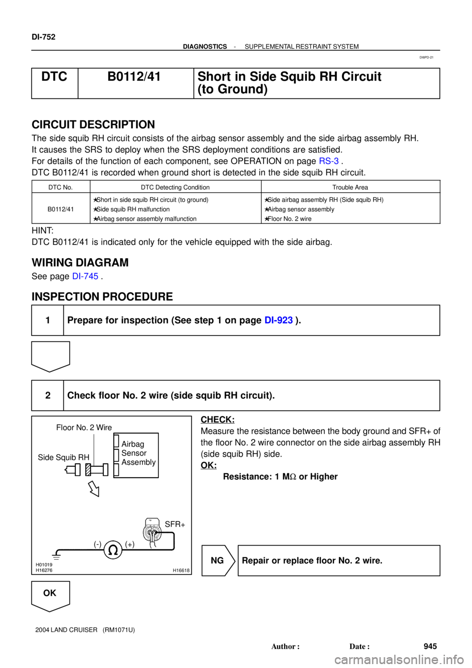
2 Check floor No. 2 wire (side squib RH circuit).
CHECK:
Measure the resistance between the body ground and SFR+ of
the floor No. 2 wire connector on the side airbag assembly RH
(side squib RH) side.
OK:
Resistance: 1 MW or Higher
NG Repair or replace floor No. 2 wire.
OK
DI6PD-21
Page 1536 of 3115
H01019AB0119H16277H16621
Side Squib RHAirbag
Sensor
Assembly
(-) (+)SFR+
ON
Floor No. 2 Wire
- DIAGNOSTICSSUPPLEMENTAL RESTRAINT SYSTEM
DI-755
948 Author�: Date�:
2004 LAND CRUISER (RM1071U)
DTC B0113/42 Short in Side Squib RH Circuit (to B+)
CIRCUIT DESCRIPTION
The side squib RH circuit consists of the airbag sensor assembly and the side airbag assembly RH.
It causes the SRS to deploy when the SRS deployment conditions are satisfied.
For details of the function of each component, see OPERATION on page RS-3.
DTC B0113/42 is recorded when a B+ short is detected in the side squib RH circuit.
DTC No.DTC Detecting ConditionTrouble Area
B0113/42
�Short in side squib RH circuit (to B+)
�Side squib RH malfunction
�Airbag sensor assembly malfunction�Side airbag assembly RH (Side squib RH)
�Airbag sensor assembly
�Floor No. 2 wire
HINT:
DTC B0113/42 is indicated only for the vehicle equipped with the side airbag.
WIRING DIAGRAM
See page DI-745.
INSPECTION PROCEDURE
1 Prepare for inspection (See step 1 on page DI-923).
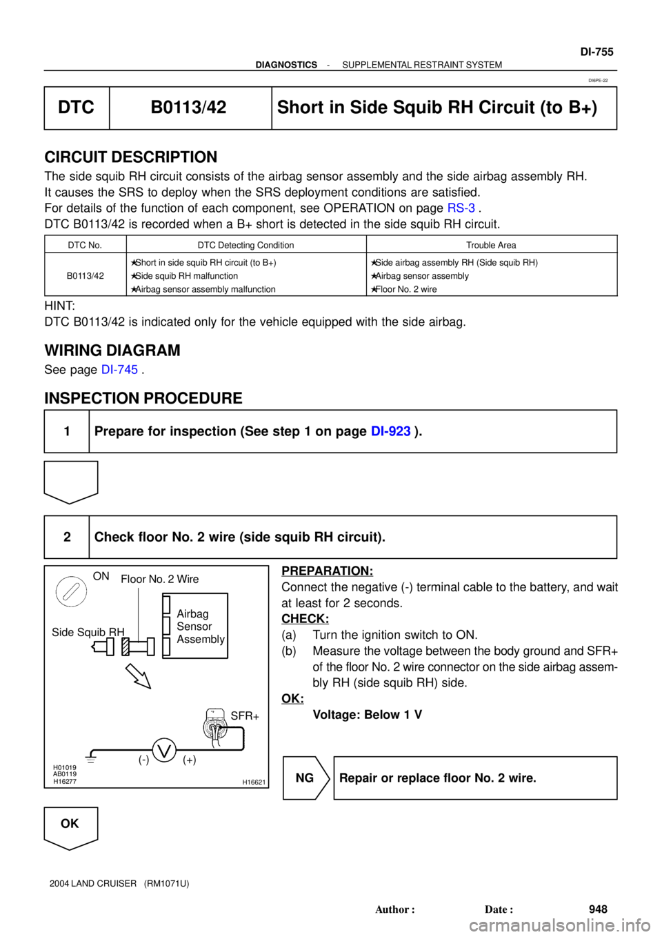
2 Check floor No. 2 wire (side squib RH circuit).
PREPARATION:
Connect the negative (-) terminal cable to the battery, and wait
at least for 2 seconds.
CHECK:
(a) Turn the ignition switch to ON.
(b) Measure the voltage between the body ground and SFR+
of the floor No. 2 wire connector on the side airbag assem-
bly RH (side squib RH) side.
OK:
Voltage: Below 1 V
NG Repair or replace floor No. 2 wire.
OK
DI6PE-22
Page 1539 of 3115
H01454
S18
Side Squib LHAirbag Sensor Assembly
SFL+
SFL- Y-R
Y-G 1
211 12
C25
C25 (*1)
(*1)
*1: w/ Side Airbag DI-758
- DIAGNOSTICSSUPPLEMENTAL RESTRAINT SYSTEM
951 Author�: Date�:
2004 LAND CRUISER (RM1071U)
DTC B0115/47 Short in Side Squib LH Circuit
CIRCUIT DESCRIPTION
The side squib LH circuit consists of the airbag sensor assembly and the side airbag assembly LH.
It causes the SRS to deploy when the SRS deployment conditions are satisfied.
For details of the function of each component, see OPERATION on page RS-3.
DTC B0115/47 is recorded when a short is detected in the side squib LH circuit.
DTC No.DTC Detecting ConditionTrouble Area
B0115/47
�Short in side squib LH circuit
�Side squib LH malfunction
�Airbag sensor assembly malfunction�Side airbag assembly LH (Side squib LH)
�Airbag sensor assembly
�Floor No. 1 wire
HINT:
DTC B0115/47 is indicated only for the vehicle equipped with the side airbag.
WIRING DIAGRAM
DI6PF-34
Page 1543 of 3115
H01019H16275H16623
Side Squib LHAirbag
Sensor
Assembly
(-) (+)
SFL- SFL+ Floor No. 1 Wire
DI-762
- DIAGNOSTICSSUPPLEMENTAL RESTRAINT SYSTEM
955 Author�: Date�:
2004 LAND CRUISER (RM1071U)
DTC B0116/48 Open in Side Squib LH Circuit
CIRCUIT DESCRIPTION
The side squib LH circuit consists of the airbag sensor assembly and the side airbag assembly LH.
It causes the SRS to deploy when the SRS deployment conditions are satisfied.
For details of the function of each component, see OPERATION on page RS-3.
DTC B0116/48 is recorded when an open is detected in the side squib LH circuit.
DTC No.DTC Detecting ConditionTrouble Area
B0116/48
�Open in side squib LH circuit
�Side squib LH malfunction
�Airbag sensor assembly malfunction�Side airbag assembly LH (Side squib LH)
�Airbag sensor assembly
�Floor No. 1 wire
HINT:
DTC B0116/48 is indicated only for the vehicle equipped with the side airbag.
WIRING DIAGRAM
See page DI-758.
INSPECTION PROCEDURE
1 Prepare for inspection (See step 1 on page DI-923).
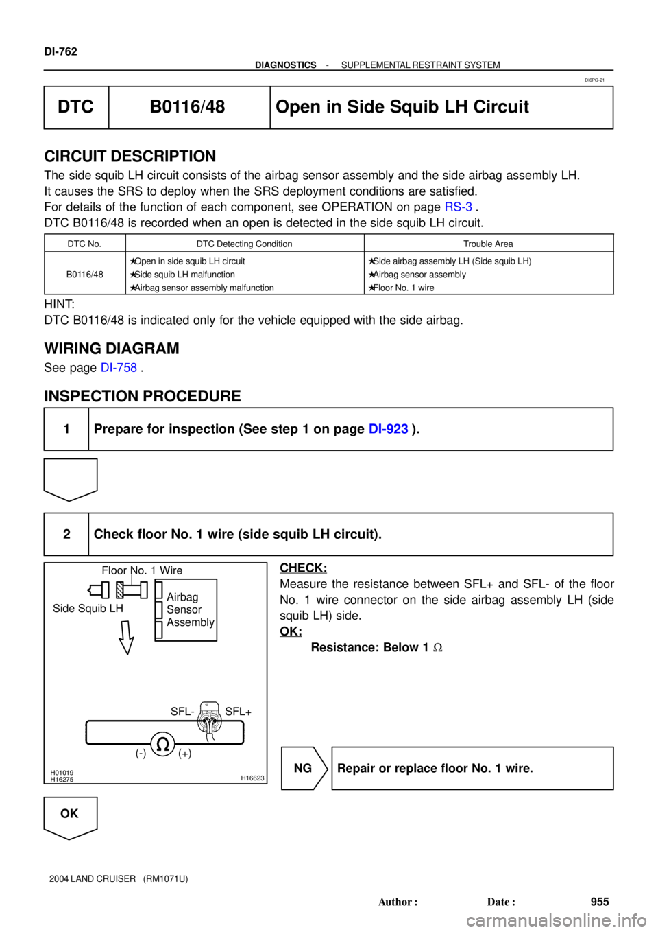
2 Check floor No. 1 wire (side squib LH circuit).
CHECK:
Measure the resistance between SFL+ and SFL- of the floor
No. 1 wire connector on the side airbag assembly LH (side
squib LH) side.
OK:
Resistance: Below 1 W
NG Repair or replace floor No. 1 wire.
OK
DI6PG-21
Page 1546 of 3115
H16276H01016H20674
Side Squib LH
Airbag
Sensor
Assembly
(-) (+)
SFL+ Floor No. 1 Wire
- DIAGNOSTICSSUPPLEMENTAL RESTRAINT SYSTEM
DI-765
958 Author�: Date�:
2004 LAND CRUISER (RM1071U)
DTC B0117/45 Short in Side Squib LH Circuit
(to Ground)
CIRCUIT DESCRIPTION
The side squib LH circuit consists of the airbag sensor assembly and the side airbag assembly LH.
It causes the SRS to deploy when the SRS deployment conditions are satisfied.
For details of the function of each component, see OPERATION on page RS-3.
DTC B0117/45 is recorded when ground short is detected in the side squib LH circuit.
DTC No.DTC Detecting ConditionTrouble Area
B0117/45
�Short in side squib LH circuit (to ground)
�Side squib LH malfunction
�Airbag sensor assembly malfunction�Side airbag assembly LH (Side squib LH)
�Airbag sensor assembly
�Floor No. 1 wire
HINT:
DTC B0117/45 is indicated only for the vehicle equipped with the side airbag.
WIRING DIAGRAM
See page DI-758.
INSPECTION PROCEDURE
1 Prepare for inspection (See step 1 on page DI-923).
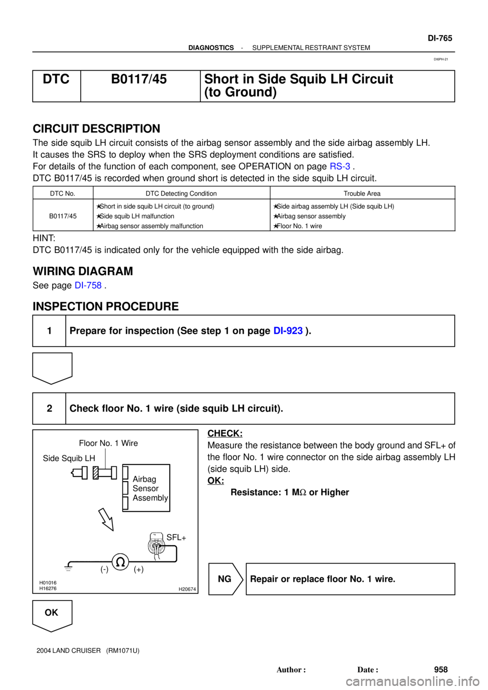
2 Check floor No. 1 wire (side squib LH circuit).
CHECK:
Measure the resistance between the body ground and SFL+ of
the floor No. 1 wire connector on the side airbag assembly LH
(side squib LH) side.
OK:
Resistance: 1 MW or Higher
NG Repair or replace floor No. 1 wire.
OK
DI6PH-21
Page 1549 of 3115
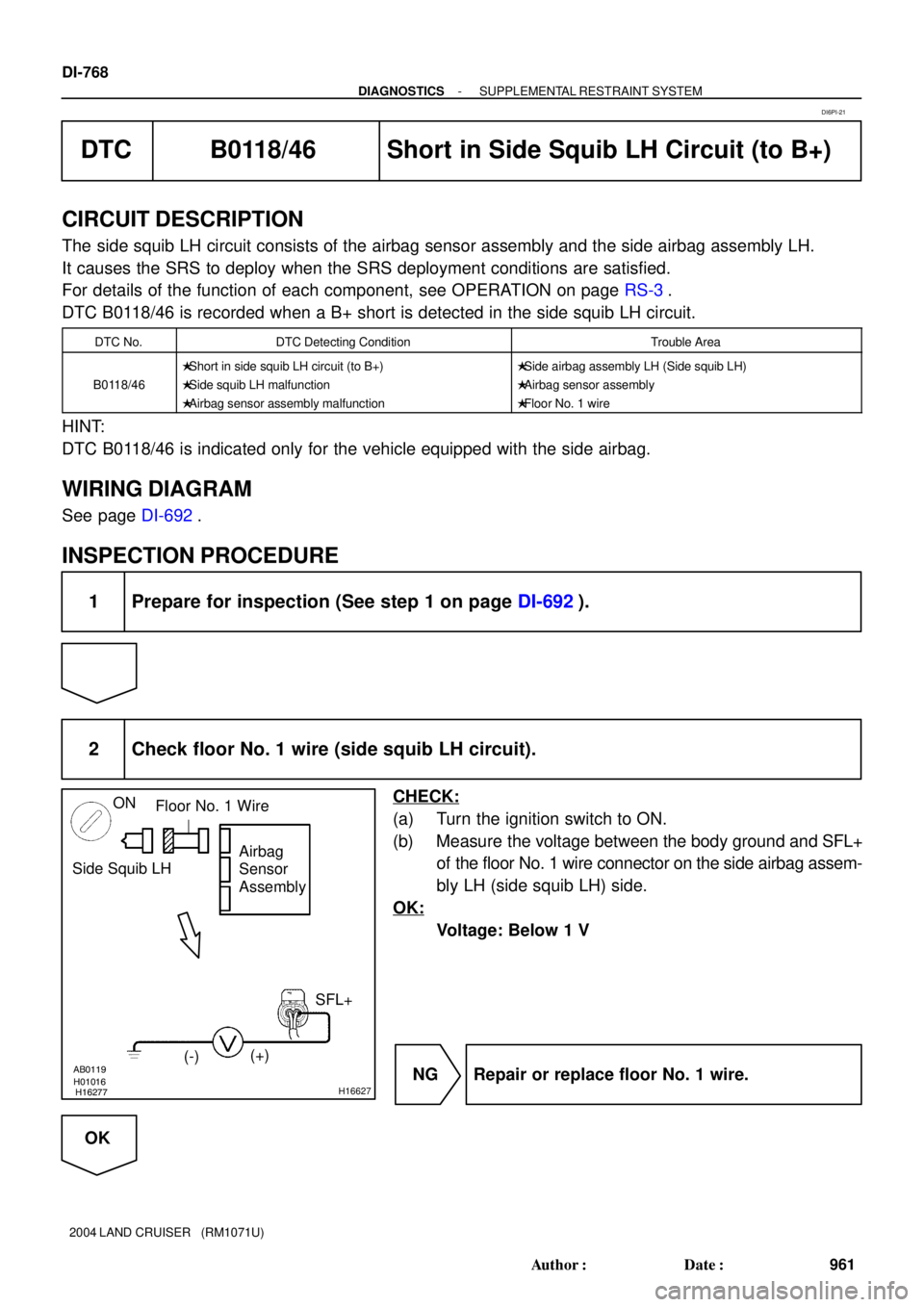
H01016AB0119
H16277H16627
Side Squib LHAirbag
Sensor
Assembly
SFL+
(-)(+)
ON
Floor No. 1 Wire
DI-768
- DIAGNOSTICSSUPPLEMENTAL RESTRAINT SYSTEM
961 Author�: Date�:
2004 LAND CRUISER (RM1071U)
DTC B0118/46 Short in Side Squib LH Circuit (to B+)
CIRCUIT DESCRIPTION
The side squib LH circuit consists of the airbag sensor assembly and the side airbag assembly LH.
It causes the SRS to deploy when the SRS deployment conditions are satisfied.
For details of the function of each component, see OPERATION on page RS-3.
DTC B0118/46 is recorded when a B+ short is detected in the side squib LH circuit.
DTC No.DTC Detecting ConditionTrouble Area
B0118/46
�Short in side squib LH circuit (to B+)
�Side squib LH malfunction
�Airbag sensor assembly malfunction�Side airbag assembly LH (Side squib LH)
�Airbag sensor assembly
�Floor No. 1 wire
HINT:
DTC B0118/46 is indicated only for the vehicle equipped with the side airbag.
WIRING DIAGRAM
See page DI-692.
INSPECTION PROCEDURE
1 Prepare for inspection (See step 1 on page DI-692).
2 Check floor No. 1 wire (side squib LH circuit).
CHECK:
(a) Turn the ignition switch to ON.
(b) Measure the voltage between the body ground and SFL+
of the floor No. 1 wire connector on the side airbag assem-
bly LH (side squib LH) side.
OK:
Voltage: Below 1 V
NG Repair or replace floor No. 1 wire.
OK
DI6PI-21
Page 1552 of 3115
H21792
B5 Buckle Switch LH
Airbag Sensor Assembly
BM2
1G19
C25LBE+
C2511
G
(*1) (*2) 3
*1: w/ Side Airbag
*2: w/o Side Airbag
- DIAGNOSTICSSUPPLEMENTAL RESTRAINT SYSTEM
DI-771
964 Author�: Date�:
2004 LAND CRUISER (RM1071U)
DTC B0126/B0127/27 Seat Belt Buckle Switch LH
Malfunction
CIRCUIT DESCRIPTION
The seat belt buckle switch LH malfunction circuit consists of the airbag sensor assembly and the front seat
inner belt LH (seat belt buckle switch LH).
For details of the function of each component, see OPERATION on page RS-3.
DTC B0126/B0127/27 is recorded when a malfunction is detected in the seat belt buckle switch LH circuit.
DTC No.DTC Detecting ConditionTrouble Area
B0126/B0127/27�Seat belt buckle switch LH circuit malfunction
�Front seat inner belt LH (Seat belt buckle switch LH)
�Airbag sensor assembly
�Floor No. 1 wire
�Front seat wire LH
WIRING DIAGRAM
DIB3R-01
Page 1558 of 3115
H21793
P22
P/T Squib RHAirbag Sensor Assembly
PR+
PR- 1
2109
C27 Y-B
YC27
C27 C275
6
(*2) (*1)(*2) (*1)
*1: w/ Side Airbag
*2: w/o Side Airbag
- DIAGNOSTICSSUPPLEMENTAL RESTRAINT SYSTEM
DI-777
970 Author�: Date�:
2004 LAND CRUISER (RM1071U)
DTC B0130/63 Short in P/T Squib RH Circuit
CIRCUIT DESCRIPTION
The P/T squib RH circuit consists of the airbag sensor assembly and the seat belt pretensioner RH.
It causes the SRS to deploy when the SRS deployment conditions are satisfied.
For details of the function of each component, see OPERATION on page RS-3.
DTC B0130/63 is recorded when a short is detected in the P/T squib RH circuit.
DTC No.DTC Detecting ConditionTrouble Area
B0130/63
�Short in P/T squib RH circuit
�P/T squib RH malfunction
�Airbag sensor assembly malfunction�Seat belt pretensioner RH (P/T squib RH)
�Airbag sensor assembly
�Floor No. 2 wire
WIRING DIAGRAM
DI6PJ-26