Page 1674 of 3115
H19244H21259H21225
D2+
(-) (+)
D Squib
(2nd step)
Spiral
Cable
Airbag
Sensor
Assembly
- DIAGNOSTICSSUPPLEMENTAL RESTRAINT SYSTEM
DI-893
1086 Author�: Date�:
2004 LAND CRUISER (RM1071U)
DTC B1182/19 Short in D Squib (2nd step) Circuit
(to Ground)
CIRCUIT DESCRIPTION
The D squib (2nd step) circuit consists of the airbag sensor assembly, the spiral cable and the steering wheel
pad.
It causes the SRS to deploy when the SRS deployment conditions are satisfied.
For details of the function of each component, see OPERATION on page RS-3.
DTC B0102/11 is recorded when a ground short is detected in the D squib (2nd step) circuit.
DTC No.DTC Detecting ConditionTrouble Area
B1182/19
�Short in D squib (2nd step) circuit (to ground)
�D squib (2nd step) malfunction
�Spiral cable malfunction
�Airbag sensor assembly malfunction�Steering wheel pad (D squib (2nd step))
�Spiral cable
�Airbag sensor assembly
�Dash wire
�Column wire
WIRING DIAGRAM
See page DI-882.
INSPECTION PROCEDURE
1 Prepare for inspection (See step 1 on page DI-692).
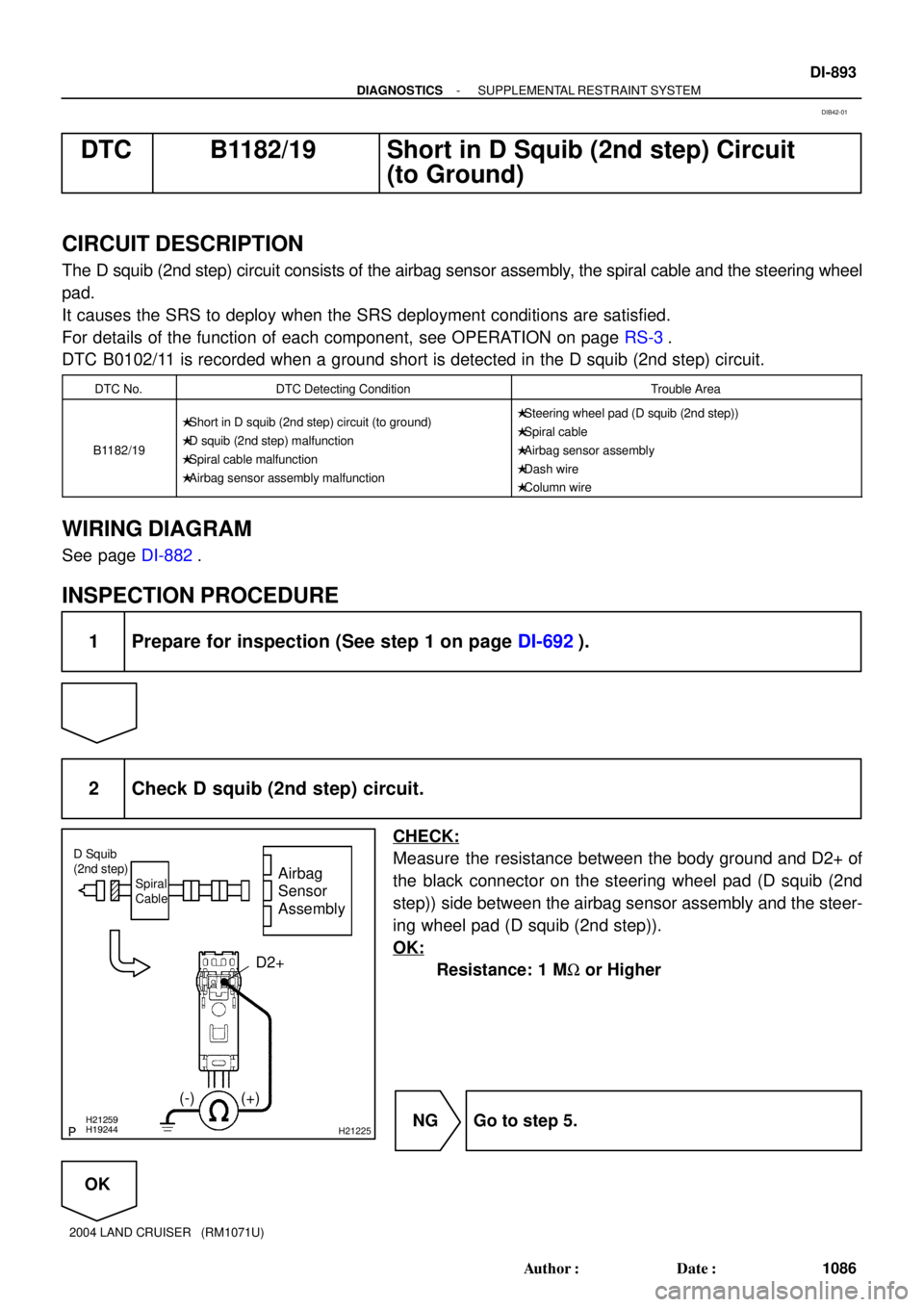
2 Check D squib (2nd step) circuit.
CHECK:
Measure the resistance between the body ground and D2+ of
the black connector on the steering wheel pad (D squib (2nd
step)) side between the airbag sensor assembly and the steer-
ing wheel pad (D squib (2nd step)).
OK:
Resistance: 1 MW or Higher
NG Go to step 5.
OK
DIB42-01
Page 1679 of 3115
AB0119H19245
H21259
H21229
D2+
(-) (+)
ON
Airbag
Sensor
AssemblySpiral
Cable D Squib
(2nd step)
DI-898
- DIAGNOSTICSSUPPLEMENTAL RESTRAINT SYSTEM
1091 Author�: Date�:
2004 LAND CRUISER (RM1071U)
DTC B1183/22 Short in D Squib (2nd step) Circuit
(to B+)
CIRCUIT DESCRIPTION
The D squib (2nd step)circuit consists of the airbag sensor assembly, the spiral cable and the steering wheel
pad.
It causes the SRS to deploy when the SRS deployment conditions are satisfied.
For details of the function of each component, see OPERATION on page RS-3.
DTC B1183/22 is recorded when a B+ short is detected in the D squib (2nd step) circuit.
DTC No.DTC Detecting ConditionTrouble Area
B1183/22
�Short in D squib (2nd step) circuit (to B+)
�D squib (2nd step) malfunction
�Spiral cable malfunction
�Airbag sensor assembly malfunction�Steering wheel pad (D squib (2nd step))
�Spiral cable
�Airbag sensor assembly
�Dash wire
�Column wire
WIRING DIAGRAM
See page DI-882.
INSPECTION PROCEDURE
1 Prepare for inspection (See step 1 on page DI-923).
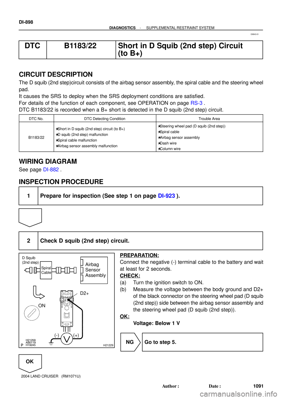
2 Check D squib (2nd step) circuit.
PREPARATION:
Connect the negative (-) terminal cable to the battery and wait
at least for 2 seconds.
CHECK:
(a) Turn the ignition switch to ON.
(b) Measure the voltage between the body ground and D2+
of the black connector on the steering wheel pad (D squib
(2nd step)) side between the airbag sensor assembly and
the steering wheel pad (D squib (2nd step)).
OK:
Voltage: Below 1 V
NG Go to step 5.
OK
DIB43-01
Page 1684 of 3115
H01454
A27
P Squib (2nd step)
8Airbag Sensor Assembly
4Y-GR
C26
Y-P 3
7P2+
P2-
C26
- DIAGNOSTICSSUPPLEMENTAL RESTRAINT SYSTEM
DI-903
1096 Author�: Date�:
2004 LAND CRUISER (RM1071U)
DTC B1185/57 Short in P Squib (2nd step) Circuit
CIRCUIT DESCRIPTION
The P squib (2nd step) circuit consists of the airbag sensor assembly and the front passenger airbag assem-
bly. It causes the SRS to deploy when the SRS deployment conditions are satisfied.
For details of the function of each component, see OPERATION on page RS-3.
DTC B1185/57 is recorded when a short is detected in the P squib (2nd step) circuit.
DTC No.DTC Detecting ConditionTrouble Area
B1185/57
�Short in P squib (2nd step) circuit
�P squib (2nd step) malfunction
�Airbag sensor assembly malfunction�Front passenger airbag assembly (P squib (2nd step))
�Airbag sensor assembly
�Dash wire
WIRING DIAGRAM
DI8F0-06
Page 1688 of 3115
R14286H16852H17147
P Squib
(2nd step)
Airbag
Sensor
Assembly
P2+
P2-
(-) (+)
Dash Wire
- DIAGNOSTICSSUPPLEMENTAL RESTRAINT SYSTEM
DI-907
1100 Author�: Date�:
2004 LAND CRUISER (RM1071U)
DTC B1186/58 Open in P Squib (2nd step) Circuit
CIRCUIT DESCRIPTION
The P squib (2nd step) circuit consists of the airbag sensor assembly and the front passenger airbag assem-
bly.
It causes the SRS to deploy when the SRS deployment conditions are satisfied.
For details of the function of each component, see OPERATION on page RS-3.
DTC B1186/58 is recorded when an open is detected in the P squib (2nd step) circuit.
DTC No.DTC Detecting ConditionTrouble Area
B1186/58
�Open in P squib (2nd step) circuit
�P squib (2nd step) malfunction
�Airbag sensor assembly malfunction�Front passenger airbag assembly (P squib (2nd step))
�Airbag sensor assembly
�Dash wire
WIRING DIAGRAM
See page DI-903.
INSPECTION PROCEDURE
1 Prepare for inspection (See step 1 on page DI-923).
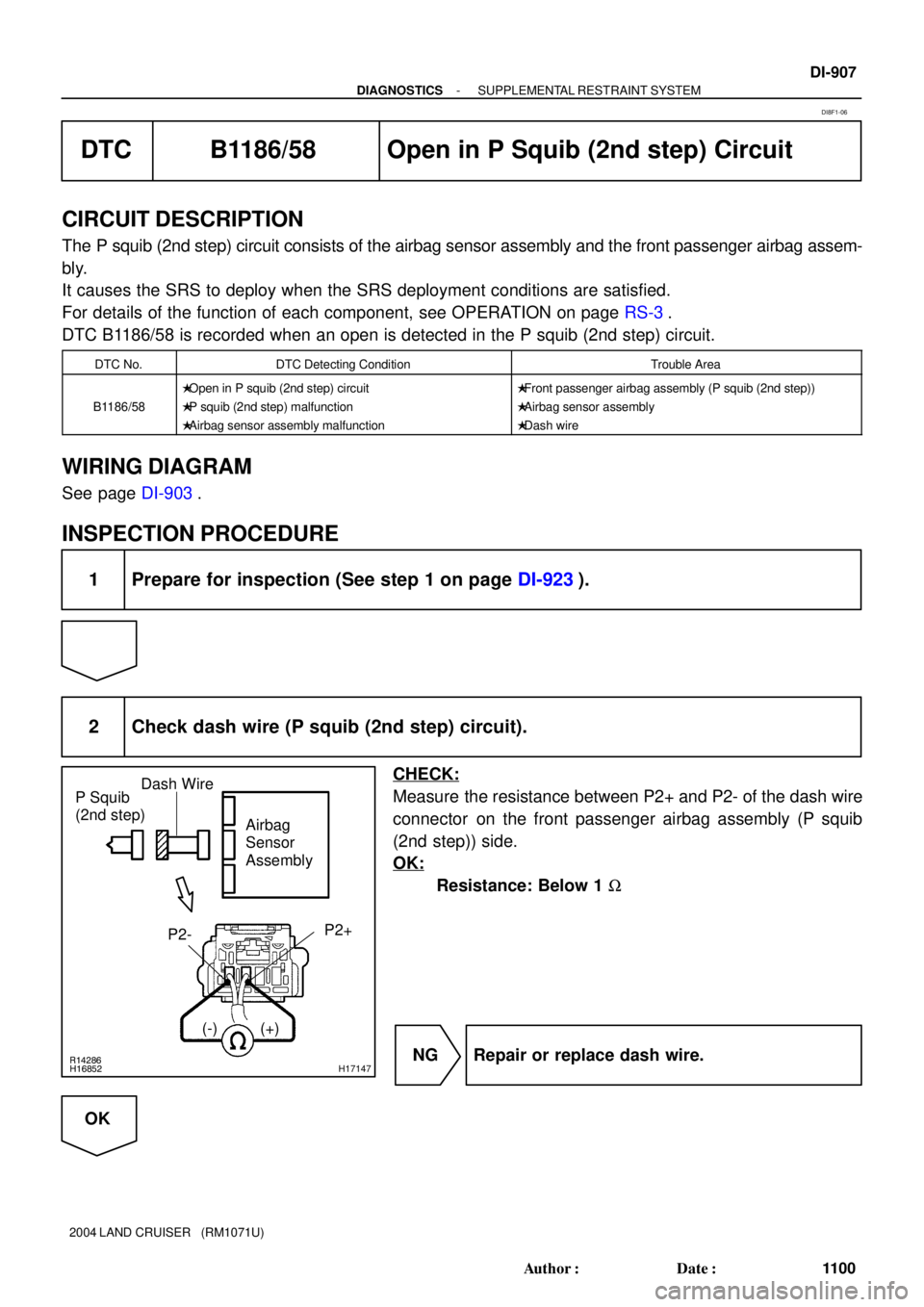
2 Check dash wire (P squib (2nd step) circuit).
CHECK:
Measure the resistance between P2+ and P2- of the dash wire
connector on the front passenger airbag assembly (P squib
(2nd step)) side.
OK:
Resistance: Below 1 W
NG Repair or replace dash wire.
OK
DI8F1-06
Page 1691 of 3115
H01227H16850H17150
P Squib
(2nd step)
Airbag
Sensor
Assembly
(+) (-)P2+
Dash Wire
DI-910
- DIAGNOSTICSSUPPLEMENTAL RESTRAINT SYSTEM
1103 Author�: Date�:
2004 LAND CRUISER (RM1071U)
DTC B1187/55 Short in P Squib (2nd step) Circuit
(to Ground)
CIRCUIT DESCRIPTION
The P squib (2nd step) circuit consists of the airbag sensor assembly and the front passenger airbag assem-
bly.
It causes the SRS to deploy when the SRS deployment conditions are satisfied.
For details of the function of each component, see OPERATION on page RS-3.
DTC B1187/55 is recorded when ground short is detected in the P squib (2nd step) circuit.
DTC No.DTC Detecting ConditionTrouble Area
B1187/55
�Short in P squib (2nd step) circuit (to ground)
�P squib (2nd step) malfunction
�Airbag sensor assembly malfunction�Front passenger airbag assembly (P squib (2nd step))
�Airbag sensor assembly
�Dash wire
WIRING DIAGRAM
See page DI-903.
INSPECTION PROCEDURE
1 Prepare for inspection (See step 1 on page DI-923).
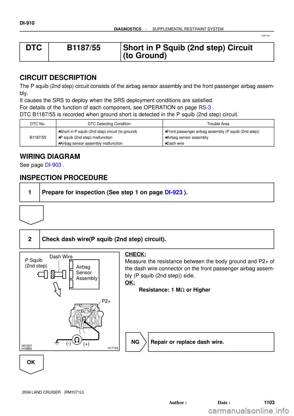
2 Check dash wire(P squib (2nd step) circuit).
CHECK:
Measure the resistance between the body ground and P2+ of
the dash wire connector on the front passenger airbag assem-
bly (P squib (2nd step)) side.
OK:
Resistance: 1 MW or Higher
NG Repair or replace dash wire.
OK
DI8F2-06
Page 1694 of 3115
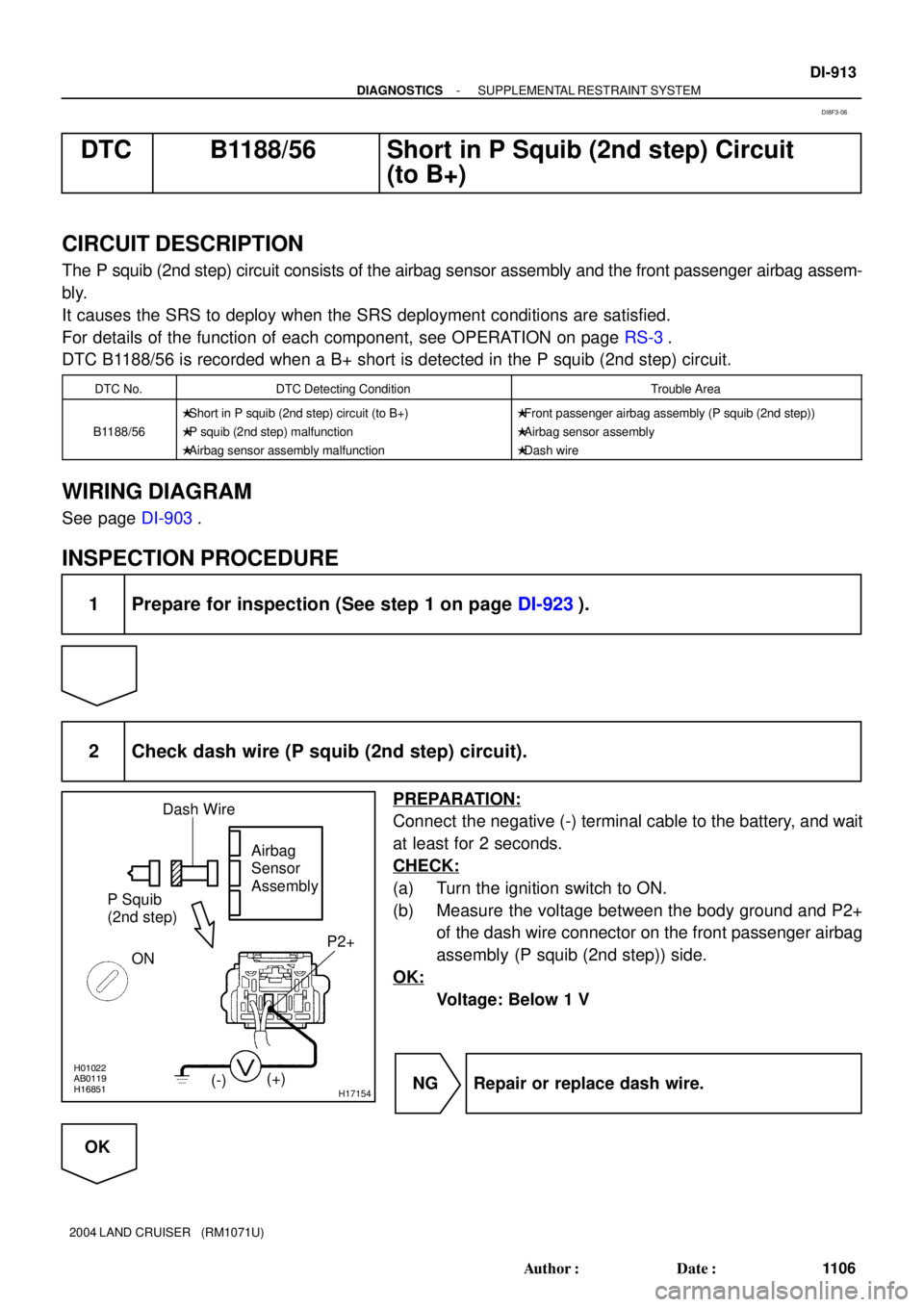
H01022AB0119H16851H17154
P Squib
(2nd step)Airbag
Sensor
Assembly
(-)(+)P2+
ONDash Wire
- DIAGNOSTICSSUPPLEMENTAL RESTRAINT SYSTEM
DI-913
1106 Author�: Date�:
2004 LAND CRUISER (RM1071U)
DTC B1188/56 Short in P Squib (2nd step) Circuit
(to B+)
CIRCUIT DESCRIPTION
The P squib (2nd step) circuit consists of the airbag sensor assembly and the front passenger airbag assem-
bly.
It causes the SRS to deploy when the SRS deployment conditions are satisfied.
For details of the function of each component, see OPERATION on page RS-3.
DTC B1188/56 is recorded when a B+ short is detected in the P squib (2nd step) circuit.
DTC No.DTC Detecting ConditionTrouble Area
B1188/56
�Short in P squib (2nd step) circuit (to B+)
�P squib (2nd step) malfunction
�Airbag sensor assembly malfunction�Front passenger airbag assembly (P squib (2nd step))
�Airbag sensor assembly
�Dash wire
WIRING DIAGRAM
See page DI-903.
INSPECTION PROCEDURE
1 Prepare for inspection (See step 1 on page DI-923).
2 Check dash wire (P squib (2nd step) circuit).
PREPARATION:
Connect the negative (-) terminal cable to the battery, and wait
at least for 2 seconds.
CHECK:
(a) Turn the ignition switch to ON.
(b) Measure the voltage between the body ground and P2+
of the dash wire connector on the front passenger airbag
assembly (P squib (2nd step)) side.
OK:
Voltage: Below 1 V
NG Repair or replace dash wire.
OK
DI8F3-06
Page 1698 of 3115
H21246
RMIL
C2625 Airbag Sensor Assembly
RMSW 21 B-W
3F 3Q69 2Cowl Side J/B RH
C26 3E4 MET
3Q7 SB
C CJ15
J/C
Combination Meter
C1210
SB
Cowl Side J/B LH
2A10
W-R2E 41
W-R
7
AM2 IG26 I18
Ignition SW
B-R
AA J4
J/CB-R
Engine Room J/B
1B9AM2
1C1
B-G F15
FL Block
MAIN
AA J12
J/C
2Q43G-W
Ia11
IU18
SB
IF13
3
IF211 4 SB
G-W
G-W
W-B RSCA Off C1319
B-R
SB J7
J/C
C C
SB SB
IFR40
RSCA Off Switch
2
BatteryCowl Side
J/B LH
- DIAGNOSTICSSUPPLEMENTAL RESTRAINT SYSTEM
DI-917
111 0 Author�: Date�:
2004 LAND CRUISER (RM1071U)
WIRING DIAGRAM
Page 1704 of 3115

H21247
Airbag Sensor
Assembly
C26IG2 5
B-R
3F3 IGN
3E4Cowl Side J/B RH
AB-R
AJ4
J/C
B-R
6 7
W-RCowl Side J/B LH
2E
2A 41 10
BatteryF15
FL Block
MAINB-G Engine Room J/B
1C 1B1 9AM2
W-R I18
Ignition SW
2 AM2 IG2
- DIAGNOSTICSSUPPLEMENTAL RESTRAINT SYSTEM
DI-923
111 6 Author�: Date�:
2004 LAND CRUISER (RM1071U)
DTC Normal Source Voltage Drop
CIRCUIT DESCRIPTION
The SRS is equipped with a voltage-increase circuit (DC-DC converter) in the airbag sensor assembly in
case the source voltage drops.
When the battery voltage drops, the voltage-increase circuit (DC-DC converter) functions to increase the
voltage of the SRS to normal voltage.
The diagnosis system malfunction display for this circuit is differ from the other circuits in that when the SRS
warning light remains on and the DTC shows a normal code, source voltage drop is indicated.
Malfunction in this circuit is not recorded in the airbag sensor assembly, and when the source voltage returns
to normal, the SRS warning light automatically goes off.
DTC No.Diagnosis
(Normal)Source voltage drop
WIRING DIAGRAM
DI8FC-09