Page 1766 of 3115
DIB5U-01
I25830
Body ECU D27
Wireless Door Lock Tuner
2PRG
RDA 4
L 8
BP4 3
B8 L
L 17
ID4 3
BP4 VV
V 18
ID43
B8 PRG
RDA
- DIAGNOSTICSWIRELESS DOOR LOCK CONTROL SYSTEM
DI-949
1142 Author�: Date�:
2004 LAND CRUISER (RM1071U)
CIRCUIT INSPECTION
DTC B1242 Wireless door lock receiver circuit mal-
function
CIRCUIT DESCRIPTION
This DTC is output when GND short of RDA terminal is detected.
DTC No.DTC Detecting ConditionTrouble Area
B1242/42GND short of RDA terminal
�Wire harness
�Wireless door lock tuner
�Body ECU (Main)
WIRING DIAGRAM
Page 1792 of 3115

EM0KQ-07
A05510
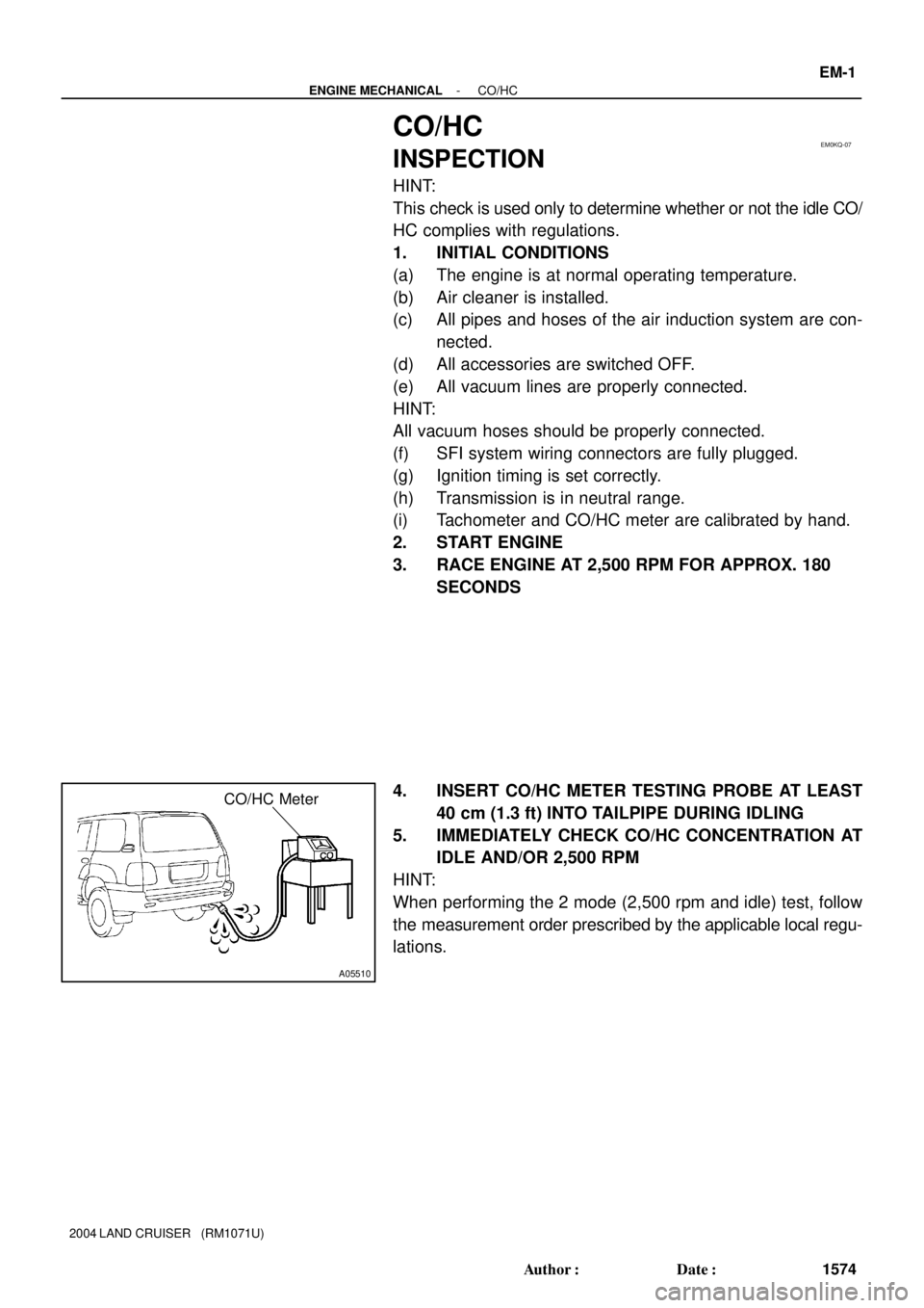
CO/HC Meter
- ENGINE MECHANICALCO/HC
EM-1
1574 Author�: Date�:
2004 LAND CRUISER (RM1071U)
CO/HC
INSPECTION
HINT:
This check is used only to determine whether or not the idle CO/
HC complies with regulations.
1. INITIAL CONDITIONS
(a) The engine is at normal operating temperature.
(b) Air cleaner is installed.
(c) All pipes and hoses of the air induction system are con-
nected.
(d) All accessories are switched OFF.
(e) All vacuum lines are properly connected.
HINT:
All vacuum hoses should be properly connected.
(f) SFI system wiring connectors are fully plugged.
(g) Ignition timing is set correctly.
(h) Transmission is in neutral range.
(i) Tachometer and CO/HC meter are calibrated by hand.
2. START ENGINE
3. RACE ENGINE AT 2,500 RPM FOR APPROX. 180
SECONDS
4. INSERT CO/HC METER TESTING PROBE AT LEAST
40 cm (1.3 ft) INTO TAILPIPE DURING IDLING
5. IMMEDIATELY CHECK CO/HC CONCENTRATION AT
IDLE AND/OR 2,500 RPM
HINT:
When performing the 2 mode (2,500 rpm and idle) test, follow
the measurement order prescribed by the applicable local regu-
lations.
Page 1880 of 3115

A05126
A05125
A05172
Lift
Down
- ENGINE MECHANICALENGINE UNIT
EM-79
1652 Author�: Date�:
2004 LAND CRUISER (RM1071U)
18. DISCONNECT PS PUMP FROM ENGINE
Remove the 3 bolts, and disconnect the PS pump from the en-
gine.
HINT:
Suspend the PS pump securely.
19. REMOVE ENGINE AND TRANSMISSION ASSEMBLY
FROM VEHICLE
(a) Attach the engine chain hoist to the engine hangers.
(b) Remove the 2 nuts and the 4 bolts holding the engine
mounting brackets to the frame brackets.
(c) Remove the 3 bolts and the transfer case protector.
(d) Remove the 8 bolts, the 2 nuts and the frame crossmem-
ber.
(e) Lift the engine and take out from the vehicle slowly and
carefully.
HINT:
Make sure the engine is clear of all wiring, hoses and cables.
(f) Place the engine and transmission assembly onto a
stand.
20. DISCONNECT ENGINE WIRE FROM TRANSMISSION
(a) Disconnect the 5 connectors.
(b) Disconnect the 2 wire clamps.
21. REMOVE OIL COOLER PIPES FOR TRANSMISSION
(a) Remove the 3 bolts and the 3 stays.
(b) Loosen the 2 union nuts, and remove the 2 oil cooler
pipes.
Page 1883 of 3115
EM0KU-10
- ENGINE MECHANICALIDLE SPEED
EM-1 1
1584 Author�: Date�:
2004 LAND CRUISER (RM1071U)
IDLE SPEED
INSPECTION
1. INITIAL CONDITIONS
(a) Engine is at normal operating temperature
(b) Air cleaner is installed
(c) All pipes and hoses of air induction systems are connected
(d) All accessories are switched OFF
(e) All vacuum lines are properly connected
HINT:
All vacuum hoses should be properly connected.
(f) SFI system wiring connectors are fully plugged
(g) Ignition timing is set correctly
(h) Transmission is in neutral position
(i) Air conditioning switches are OFF
2. CONNECT TOYOTA HAND-HELD TESTER OR OBD II SCAN TOOL
(See page EM-9)
3. INSPECT IDLE SPEED
(a) Race the engine speed at 2,500 rpm for approx. 90 seconds.
(b) Check the idle speed.
Idle speed: 700 ± 50 rpm
If the idle speed is not as specified, check the air intake system.
4. DISCONNECT TOYOTA HAND-HELD TESTER OR OBD II SCAN TOOL
Page 1907 of 3115
NOTICE
When handling supplemental restraint system components (removal,
installation or inspection, etc.), always follow the direction given in the repair
manuals listed above to prevent accidents and supplemental restraint
system malfunction.
FOREWORD
This wiring diagram manual has been prepared to provide
information on the electrical system of the 2004 LAND
CRUISER.
Applicable models: UZJ100 Series
For service specifications and repair procedures of the above
models other than those listed in this manual, refer to the
following manuals;
Manual Name
Pub. No.
�2004 LAND CRUISER Repair Manual
Volume 1
Volume 2
�2004 TOYOTA New Car Features
RM1071U1
RM1071U2
NCF257U
All information in this manual is based on the latest product
information at the time of publication. However, specifications
and procedures are subject to change without notice.
Page 1908 of 3115

�2003
All rights reserved. This book may not be
reproduced or copied, in whole or in part, without
the written permission of Toyota Motor
Corporation.
2004 LAND CRUISER (EWD548U)
1
2004 LAND CRUISER
ELECTRICAL WIRING DIAGRAM
Section Code Page
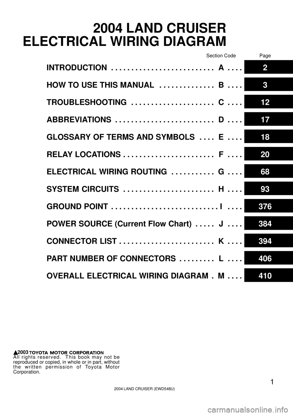
INTRODUCTION A. . . . . . . . . . . . . . . . . . . . . . . . . . . . . . 2
HOW TO USE THIS MANUAL B. . . . . . . . . . . . . . . . . .
3
TROUBLESHOOTING C. . . . . . . . . . . . . . . . . . . . . . . . .
12
ABBREVIATIONS D. . . . . . . . . . . . . . . . . . . . . . . . . . . . .
17
GLOSSARY OF TERMS AND SYMBOLS E. . . . . . . .
18
RELAY LOCATIONS F. . . . . . . . . . . . . . . . . . . . . . . . . . .
20
ELECTRICAL WIRING ROUTING G. . . . . . . . . . . . . . .
68
SYSTEM CIRCUITS H. . . . . . . . . . . . . . . . . . . . . . . . . . .
93
GROUND POINT I. . . . . . . . . . . . . . . . . . . . . . . . . . . . . . .
376
POWER SOURCE (Current Flow Chart) J. . . . . . . . .
384
CONNECTOR LIST K. . . . . . . . . . . . . . . . . . . . . . . . . . . .
394
PART NUMBER OF CONNECTORS L. . . . . . . . . . . . .
406
OVERALL ELECTRICAL WIRING DIAGRAM M. . . . .
410
Page 1909 of 3115

2004 LAND CRUISER (EWD548U)
2A INTRODUCTION
This manual consists of the following 13 sections:
No.
SectionDescription
A
INDEXIndex of the contents of this manual.
A
INTRODUCTIONBrief explanation of each section.
BHOW TO USE THIS
MANUALInstructions on how to use this manual.
CTROUBLE-
SHOOTINGDescribes the basic inspection procedures for electrical circuits.
DABBREVIATIONSDefines the abbreviations used in this manual.
E
GLOSSARY OF
TERMS AND
SYMBOLS
Defines the symbols and functions of major parts.
FRELAY LOCATIONSShows position of the Electronic Control Unit, Relays, Relay Block, etc.
This section is closely related to the system circuit.
GELECTRICAL
WIRING ROUTINGDescribes position of Parts Connectors, Splice points, Ground points, etc.
This section is closely related to the system circuit.
INDEXIndex of the system circuits.
H
SYSTEM CIRCUITS
Electrical circuits of each system are shown from the power supply through ground
points. Wiring connections and their positions are shown and classified by code
according to the connection method. (Refer to the section, ºHow to use this manualº).
The ºSystem Outlineº and ºService Hintsº useful for troubleshooting are also contained
in this section.
IGROUND POINTShows ground positions of all parts described in this manual.
JPOWER SOURCE
(Current Flow Chart)Describes power distribution from the power supply to various electrical loads.
KCONNECTOR LISTDescribes the form of the connectors for the parts appeared in this book.
This section is closely related to the system circuit.
LPART NUMBER OF
CONNECTORSIndicates the part number of the connectors used in this manual.
M
OVERALL
ELECTRICAL
WIRING DIAGRAM
Provides circuit diagrams showing the circuit connections.
Page 1910 of 3115

2004 LAND CRUISER (EWD548U)
3 HOW TO USE THIS MANUAL B
This manual provides information on the electrical circuits installed on vehicles by
dividing them into a circuit for each system.
The actual wiring of each system circuit is shown from the point where the power
source is received from the battery as far as each ground point. (All circuit
diagrams are shown with the switches in the OFF position.)
When troubleshooting any problem, first understand the operation of the circuit
where the problem was detected (see System Circuit section), the power source
supplying power to that circuit (see Power Source section), and the ground points
(see Ground Point section). See the System Outline to understand the circuit
operation.
When the circuit operation is understood, begin troubleshooting of the problem
circuit to isolate the cause. Use Relay Location and Electrical Wiring Routing
sections to find each part, junction block and wiring harness connectors, wiring
harness and wiring harness connectors, splice points, and ground points of each
system circuit. Internal wiring for each junction block is also provided for better
understanding of connection within a junction block.
Wiring related to each system is indicated in each system circuit by arrows
(from__, to__). When overall connections are required, see the Overall Electrical
Wiring Diagram at the end of this manual.